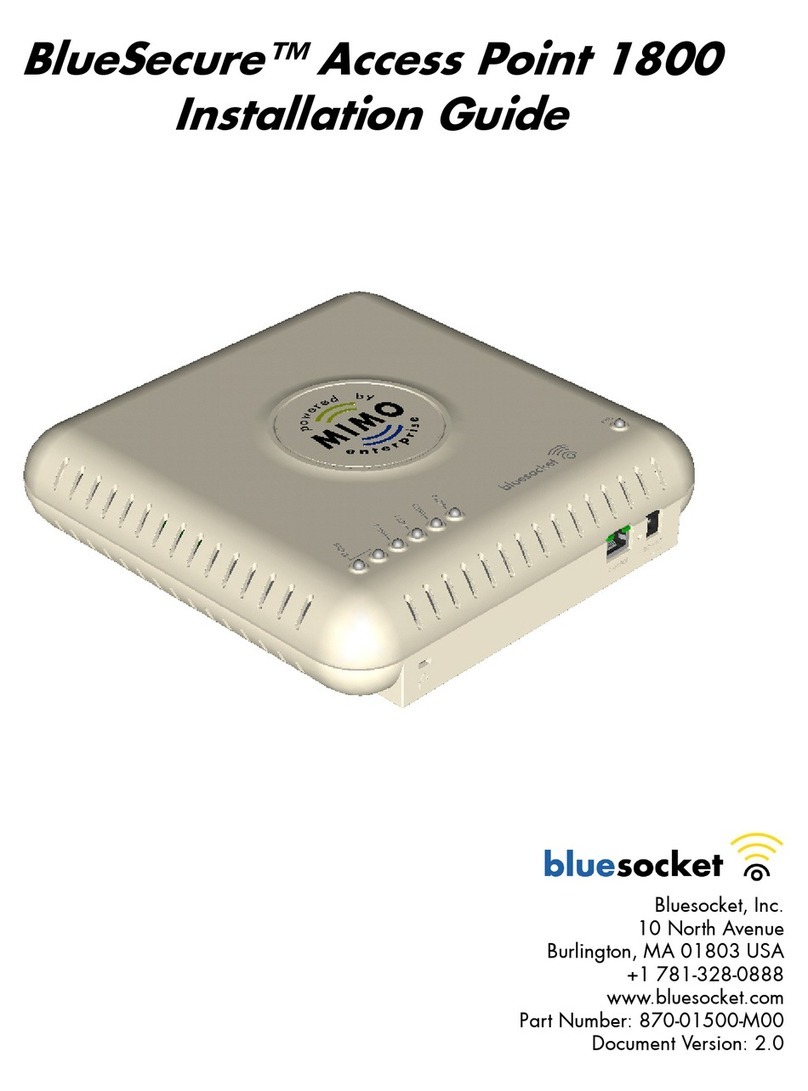
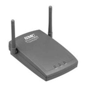
Bluesocket BlueSecure 1700 User manual

BlueSecure™ Access Point 1700
Installation Guide
Bluesocket, Inc.
10 North Avenue
Burlington, MA 01803 USA
+1 781-328-0888
www.bluesocket.com
Part Number: 870-01500-M00
Document Version: 5.0

ii
Copyright Notice
Copyright © 2006 Bluesocket, Inc. All rights reserved.
No part of this document may be reproduced in any form or by any means, electronic or manual, including
photocopying without the written permission of Bluesocket, Inc.
The products described in this document may be protected by one or more U.S. patents, foreign patents, or pending
patents.
This document is provided “as is” without warranty of any kind, either express or implied, including, but not limited to,
the implied warranties of merchantability, fitness for a particular purpose, or non-infringement. This publication could
include technical inaccuracies or typographical errors. Changes are periodically added to the information herein; these
changes will be incorporated in new editions of the document. Bluesocket inc. may make improvements or changes in the
products or the programs described in this document at any time.
Trademarks
Bluesocket, The Bluesocket Logo, Secure Mobility, BlueView, BlueSecure, HighDataDensity, DynamicRF, and CellularLAN
are trademarks or registered trademarks of Bluesocket, Inc.
All other trademarks, trade names and company names referenced herein are used for identification purposes only and
are the property of their respective owners.
Publication Date: October 9, 2006

BlueSecure™ AP 1500 Installation Guide iii
Contents
Overview .................................................................................................1
Familiarizing Yourself with the BSAP Hardware ............................................2
Fixed Antennas......................................................................................3
LED Indicators .......................................................................................3
Power Supply Connector ........................................................................3
Ethernet/PoE Connector .........................................................................4
Reset Button ..........................................................................................5
Console Port .........................................................................................5
Kensington Security Slot..........................................................................5
Provisioning Your Bluesocket WLAN for BSAPs .............................................5
Deploying BSAPs on the Same Layer-2 Subnet as the BSC ..........................5
Deploying BSAPs with Layer-3 Connectivity to the BSC...............................6
Selecting a BSAP Installation Location..........................................................7
Connecting and Powering the BSAP ............................................................8
Using the BSAP Command Line Interface (CLI)...............................................9
Accessing the BSAP CLI ..........................................................................9
Navigating the BSAP CLI ......................................................................10
BSAP Default Configuration...................................................................11
Setting the BSAP and Home BSC IP Addresses Using the CLI.....................11
Using the BSAP’s Site Survey Mode .......................................................12
General Specifications.............................................................................13
Declarations of Conformity and Regulatory Information................................15
Safety Warnings for BlueSecure™ Access Point 1700 .................................21
Mounting Instructions ...............................................................................32

iv
Contents

BlueSecure™ Access Point 1700 Installation Guide 1
Overview
The BlueSecure Access Point 1700 is a next-generation, “thin” access point that
works in conjunction with BlueSecure Controllers (BSCs) for enterprise wireless
LAN (WLAN) deployments. The BlueSecure Access Point 1700 features dual
radios supporting 802.11a and 802.11b/g in a plenum-rated housing, with an
embedded MIMO antenna panel under the top cover of the AP.
BSAPs are simple to configure and require only minimal provisioning to make
them fully operational on a WLAN secured and managed by a BlueSecure
Controller
BSAPs can be directly attached to any existing Layer-2 or Layer-3 Ethernet switch
and communicate with the BSC across any subnet boundary. Once the BSAP has
discovered and established Layer-2 or Layer-3 communication with its home (i.e.,
host) BlueSecure Controller, advanced configuration and provisioning may be
applied either to individual BSAPs or globally across the entire WLAN using the
BSC’s web-based Administrator Console.
Once a BlueSecure Access Point has downloaded its configuration from its home
BlueSecure Controller, the BSAP and the BSC will establish a tunnel through
which all wireless client traffic received by the BSAP will pass for the application
of policy by the BSC.
This guide provides complete installation procedures for your BSAP including:
• familiarizing yourself with the BSAP hardware
• provisioning your Bluesocket WLAN for BSAPs
• selecting a BSAP installation location
• connecting and powering the BSAP
• using the BSAP command line interface (CLI)
Figure 1: BSAPs Automatically Discover BSCs Across L2/L3 Networks

2
Familiarizing Yourself with the BSAP Hardware
Figure 2 illustrates the BSAP hardware. Familiarize yourself with the labeled
components before attempting to install the BSAP.
Figure 2: BSAP Hardware Components

Familiarizing Yourself with the BSAP Hardware
BlueSecure™ Access Point 1700 Installation Guide 3
Fixed Antennas
The BSAP-1700 utilizes an embedded MIMO antenna panel under the top cover
of the AP for wireless communications. The antennas has three elements for each
band. Two elements are used for transmit and receive and the third element is
used for receiving only. The BSAP-1700 also leverages the embedded Airgo
TrueMIMO radios and antenna panel to support high-throughput communications
with mobile devices that also use Airgo TrueMIMO chipsets.
LED Indicators
The following grouping of LED indicators is located on the top of the BSAP-1700
housing:.
The two status LEDs together indicate the following software operational modes,
depending on whether each LED is off, on, or blinking:
Link1 and Link 2 - When this LED is on, it indicates that the unit is on and the
radio active (note that when unit is booting, the LED defaults to on even though
the radio is disabled).
Act1 and Act2 - When this LED is on, it indicates data activity on the Ethernet
link.
Power Supply Connector
The BSAP does not have a power switch. It is powered on when connected to the
supplied AC power adapter, and the power adapter is connected to a power
Table 1: BSAP Status LEDs
Left Status
LED
Right Status
LED Indicates
Off Off Failure
On Off Waiting for IP Address
Blinking Off BSC discovery in progress
On On System is operational
Blinking Blinking Software download in progress
Software
Operational Modes
802.11b/g
Link/Activity
802.11a
Link/Activity

4
source. The BSAP automatically adjusts to any voltage between 100-240 volts at
50 or 60 Hz. No voltage range settings are required.
The BSAP may also receive Power over Ethernet (PoE) from a model BSC-400
Controller, switch or other network device that supplies power over the network
cable based on the IEEE 802.3af standard.
Note that if the BSAP is connected to a PoE source device and also connected to
a local power source through its AC power adapter, PoE will be disabled.
Ethernet/PoE Connector
The BSAP-1700 has one auto-sensing 10BASE-T/100BASE-TX/1000BaseT RJ-45
connector that can be attached directly to 10BASE-T/100BASE-TX/1000BaseT
switches to provide a full-duplex link. These segments must conform to the IEEE
802.3 or 802.3u specifications.
This connector uses an MDI (i.e., internal straight-through) pin configuration. You
can use straight-through twisted-pair cable to connect this port to most network
interconnection devices such as a switch or router that provide MDI-X ports.
However, when connecting the BSAP to a workstation or other device that does
not have MDI-X ports, you must use crossover twisted-pair cable.
The BSAP appears as an Ethernet node and performs a bridging function by
moving packets from the wired LAN to remote workstations on the wireless
infrastructure.
The Ethernet/PoE RJ-45 connector also supports Power over Ethernet (PoE) based
on the IEEE 802.3af standard. Note that if the BSAP is connected to a PoE source
device and also connected to a local power source through the AC power
adapter, PoE will be disabled.
802.3af specifies Power over Ethernet for “mid-span”, where PoE inserters are
located in the path between the network and the AP, as well as “DCE”, where the
power is supplied by the network switch the AP is attached to. Mid-span devices
typically provide power on the unused pairs (4+5 & 7+8), where a PoE LAN
switch will most likely provide power to the AP on the data pairs (1+2 & 3+6).
If the BSAP-1700 is connected to a PoE LAN switch at either 10BaseT, 100BaseT,
or 1000BaseT, and the switch is configured to supply 802.3af standard PoE, the
BSAP-1700 will power on and operate correctly. If the BSAP-1700 Ethernet
interface is running in either 10BaseT or 100BaseT mode, any standard-based
802.3af mid-span power inserter will work properly, including Bluesocket’s POE-
001 10/100 Mid-Span PoE Inserter.
Complication arise when using the BSAP-1700 with the Ethernet interface is
running in 1000BaseT mode. If a mid-span device is used, the device must be
compatible with 1000BaseT, such as the Bluesocket model POE-002, 1000BaseT
Mid-Span PoE Inserter. 1000BaseT Ethernet uses all 4 pairs, therefore, 10BaseT
/ 100BaseT mid-span power inserters incompatible, and will break the
communications path between the BSAP-1700 and the network.

Provisioning Your Bluesocket WLAN for BSAPs
BlueSecure™ Access Point 1700 Installation Guide 5
Reset Button
Use this button to reset the BSAP or restore its factory default configuration. If you
hold down the button for less than 5 seconds, the BSAP will perform a hardware
reset. If you hold down the button for 5 seconds or more, any configuration
changes you may have made are removed, and the factory default configuration
is restored to the BSAP.
Console Port
The BSAP-1700’s console port is available through the Ethernet interface.
Kensington Security Slot
The BSAP includes a Kensington security slot on the side panel. You can prevent
unauthorized removal of the BSAP by wrapping a Kensington security cable (not
provided) around an unmovable object, inserting the lock into the slot, and
turning the key.
Provisioning Your Bluesocket WLAN for BSAPs
There are prerequisites that must be met before deploying BSAPs in a live
network environment. These prerequisites ensure that the BSAPs are able to
discover and connect to a host BlueSecure Controller. Implementing these
prerequisites also relieves you from the need to manually configure each
deployed BSAP.
The deployment prerequisites for BSAPs are:
•BSAP IP Address - Each BSAP requires a unique IP address.
•Host BlueSecure Controller IP Address - Each BSAP also needs the IP
address of the host BSC to which it will connect and from which it will obtain
its software image and configuration.
This section describes how to provision your Bluesocket WLAN when deploying
BSAPs:
• on the same Layer-2 subnet as the BSC
• across a routed network with Layer-3 connectivity to the BSC
Deploying BSAPs on the Same Layer-2 Subnet as the BSC
If the BSAPs are on the same subnet as the home BlueSecure Controller as shown
in Figure 3, you can run a DHCP server on the BSC to manage IP address
assignment to BSAPs. In this scenario, the BlueSecure Controller must be the only
DHCP server for the subnet.
Alternatively, you can configure the BlueSecure Controller to run a DHCP relay
agent to relay DHCP communications between the BSAPs and a DHCP server on
your network.
When you run a DHCP server or a DHCP relay agent on the BSC to assign IP
addresses to BSAPs on the managed side, the BSC will also pass its IP address to
the BSAPs automatically using vendor-specific option 43. In this way, the BSAPs
will learn the home BSC to which they should connect.

6
See the
BlueSecure Controller Setup and Administration Guide
for detailed DHCP
server and DHCP relay agent configuration procedures.
In this deployment scenario, simply connect and power on the BSAPs. They will
automatically discover and communicate with their home BSC.
Deploying BSAPs with Layer-3 Connectivity to the BSC
You can also deploy BSAPs on a routed network with Layer-3 connectivity to the
BSC as shown in Figure 4.
In this deployment scenario, you must ensure that each BSAP is able to
communicate with the BSC across the routed network by verifying that:
• there are no NAT devices between the BSAPs and the BSC
• Protocol 97 and TCP/UDP Port 33333 traffic is allowed between the BSAPs
and the BSC
Each BSAP will receive its IP address from your existing network DHCP server.
Figure 3: Deploying BSAPs on the Same Layer-2 Subnet as the BSC
Figure 4: Deploying BSAPs Across a Routed Network
Run a DHCP Server or
a DHCP Server Relay
Agent on the BSC
BSAPs will Automatically
Discover and Communicate
with their Home BSC
Network
DHCP
Server
Network
DNS
Server
BSAPs Receive their IP
Addresses from
Network DHCP Server
BSAPs Receive Home BSC
IP Address Using DHCP
Option 43 or DNS

Selecting a BSAP Installation Location
BlueSecure™ Access Point 1700 Installation Guide 7
The BSAP also needs the IP address of the home BSC to which it will connect and
from which it will obtain its software image and configuration. You can provide
the home BSC IP address to a BSAP using one of the following methods:
•DHCP Server Option 43 - You can manually configure the DHCP server
on your network to send BSC IP addresses to BSAPs using DHCP vendor-
specific option 43.
In DHCP requests sent from the BSAP, the BSAP uses option 60 Vendor class
identifier with a value of BlueSecure.AP1700 to identify itself to the DHCP
server.
Refer to the documentation supplied with your DHCP server when configuring
vendor-specific option 43
•DNS Server Configuration - BSAPs are factory configured with
apdiscovery as the DNS hostname. You can configure a DNS server on
your network with an entry for apdiscovery with the home BSC Controller IP
address as the resolution.
To configure this, add a NAME record to the DNS server for apdiscovery (at
the domain server that the BAP will receive). Point this name to one or more
BSC IP addresses (managed, protected or VLAN depending on the network
configuration).
So for example, if there are two BSCs (192.168.100.23 and
192.168.100.28), and the domain is customer.com, add two NAME records
to customer.com, for the name apdiscovery.customer.com. One should
resolve to 192.168.100.23 and one to 192.168.100.28. PTR (i.e., pointer)
records are not needed for this portion of discovery.
Selecting a BSAP Installation Location
BlueSecure Access Points should be positioned for maximum throughput and
range between other BSAPs and wireless client devices. Normally, you should
locate the BSAP on the ceiling away from obstructions.
Range and performance are dictated by the distance between the BSAP and
client radios, and by obstacles that may be present in a specific building or office
environment. The following positioning guidelines are suggested:
• Document all the BSAPs and client devices you wish to include in your
wireless network. Record the MAC address, serial number, and placement of
each BSAP.
• Wired LAN and power connections must be available for each BSAP at the
desired installation location. If a power outlet is not available near the access
point, mid-span power inserters are recommended.
• If building blueprints or floor plans are available, use them to define potential
client device locations and likely roaming areas.
• Identify possible obstacles or sources of interference that could affect signal
strength (for example, walls, metal objects).

8
• Install the BSAP in an area where large steel structures such as beams, pillars,
shelving units, bookcases, and filing cabinets do not obstruct radio signals to
and from the BSAP.
• Determine optimal AP placement using Bluesocket’s Wireless LANPlanner
software. LANPlanner enables network planners to import a map of the
facility, note the contents and construction materials, designate user regions
and applications to be used and place equipment. The designer then
interactively simulates how the wireless signals will propagate and fine-tunes
the network design with “what if” analysis to determine optimum
performance. Please consult Bluesocket’s web site for additional information,
and to download free trial software.
• Once BSAPs have been installed and configured, use site survey and
monitoring utilities supplied with the client adapters to test signal strength at
various locations. Modify the positioning of the BSAPs and client stations as
required for optimum performance.
Connecting and Powering the BSAP
Follow these instructions to connect your BlueSecure BSAP to your Bluesocket
WLAN and then power it up:
1. Make a note of the 12-character MAC address and the serial number listed
on the bottom of the BSAP before mounting the BSAP to a wall or other
surface. You will need this information during configuration.
2. Mount the BSAP to a horizontal surface or wall.
Mounting on a Horizontal Surface
To keep the BSAP from sliding on the surface, attach the four rubber feet
supplied with your BSAP distribution to the embossed circles on the bottom of
the BSAP chassis.
Mounting on a Wall
Refer to the mounting instructions in Appendix B.
3. Position the BSAP-1700 for best radio performance.
The BSAP-1700 utilizes a 6-element MIMO antenna panel under the top
cover of the unit. This antenna panel is made up of a combination of
horizontally and vertically polarized antenna elements, which should give
excellent performance regardless of the orientation of the AP. The BSAP-1700
should, however, be place where it has the best unobstructed view of the
coverage area. If possible, mounting the BSAP-1700 on the ceiling will
provide the best performance in a typical office environment. An optional
ceiling time mounting kit is available for the BSAP-1700, which provides for a
very esthetically pleasing and professional looking installation. For more
information, please refer to Bluesocket’s web site.
4. The BSAP derives its operating power directly from the RJ-45 connector when
connected to a device that provides IEEE 802.3af compliant Power over
Ethernet (PoE).

Using the BSAP Command Line Interface (CLI)
BlueSecure™ Access Point 1700 Installation Guide 9
Caution: If the BSAP is used in a medical environment, it must use an IEC/
EN60601-1 compliant power adapter. See page 13 for a description of the
IEC/EN60601-1 compliant power adapter available from Bluesocket.
5. Verify that the PWR LED stops flashing and remains on, and that the other
status LEDs start functioning as described in the section entitled “LED
Indicators” on page 3.
6. Connect the BSAP to your Bluesocket WLAN.
You can connect the BSAP-1700 to a 10/100 Mbps Ethernet through a
network device such as a hub or a switch, or to a 1000BaseT Gigabit
Ethernet interlace. Connect the RJ-45 Ethernet connector on the BSAP’s back
panel to your network using category 3, 4, or 5 UTP Ethernet cable. When
the BSAP and the connected device are powered on, the BSAP’s Ethernet Link
LED should light indicating a valid network connection.
)Note: The RJ-45 port on the BSAP provides a full-duplex Ethernet connection
using an MDI pin configuration, so you must use a straight-through cable for
network connections to hubs or switches that only have MDI-X ports, and a
crossover cable for direct network connections to BSC-400s, PCs, servers or
other end nodes that only have MDI ports. However, if the device to which
you are connecting supports auto-MDI/MDI-X operation, you can use either a
straight-through or crossover cable.
Using the BSAP Command Line Interface (CLI)
)Note: Normally you will not need to access the BSAP CLI. In a properly
provisioned Bluesocket WLAN, the BSAP will automatically discover and
communicate with its home BSC. We recommend that you use the CLI to
configure the BSAP only in a lab or test environment, or where a pre-defined
static IP address is desired.
You can connect a console to the BSAP’s Ethernet port to perform local
configuration of the BSAP using its command line interface (CLI).You can use the
BSAP’s CLI to manually configure:
• the BSAP’s IP address
• the IP address of the home BSC from which the BSAP will download its
configuration and software image
• full- or half-power site survey mode
Accessing the BSAP CLI
Access the BSAP CLI using an SSH client (the example uses putty) For example:
1. The default management IP address for the AP-1700 is 192.168.190.1.
Configure your laptop computer to have a static IP address in this same
subnet, for example 192.168.0.2.
2. Ping the AP from the laptop to make sure it can be seen.
3. Configure putty to use SSH and then connect to the IP address of the AP (by
default 192.168.190.1) on port 2335.

10
4. Enter the following username and password in lowercase at the displayed CLI
login prompts:
BlueAP login: adm1n (i.e., adm “one” n)
Password: blue1socket (i.e., blue “one” socket)
The BSAP CLI main menu appears as shown in Figure 5.
Navigating the BSAP CLI
The BSAP CLI main menu provides access to these options:
•Network Configuration - Configure the BSAP’s network settings including
its IP address and the IP address of the BSC to which it will connect.
•Save/Apply Configuration - After you have configured the BSAP’s
network settings, you must apply them before they become active.
•Restore Defaults - Restore the BSAP to its default settings.
•Show Version Information - Display BSAP version information.
•Reboot AP - After applying the BSAP’s configuration settings, you must
reboot the BSAP to effect the new configuration.
•Toggle Half Power Site Survey Mode, Internal Antennas - Toggle
“site survey mode” on/off. In half power site survey mode, the BSAP beacons
known SSIDs with its 802.11 a and 802.11 b/g radios operating at half
power to facilitate a WLAN site survey. Rebooting the BSAP following a site
survey, restores the BSAP’s existing configuration. See page 12 for details on
using the BSAP’s site survey mode.
When operating in a submenu, press hto return directly to the main menu (or
home menu). Press pto return to the previous menu.
Figure 5: BSAP CLI Main Menu

Using the BSAP Command Line Interface (CLI)
BlueSecure™ Access Point 1700 Installation Guide 11
BSAP Default Configuration
The BSAP is shipped with the following default configuration.
IP_ADDR_MODE: DHCP (0)
IP_ADDR 0.0.0.0
NETMASK 0.0.0.0
GW_ADDR 0.0.0.0
DNS_ADDR 0.0.0.0
WG_ADDR_MODE Discover BSC (0)
WG_ADDR 0.0.0.0
The two options for IP address mode are:
• (0) DHCP - The BSAP runs a DHCP client and receives its IP address from a
DHCP server.
• (1) Static IP - You assign the BSAP a static IP address via its CLI.
The two options for WG address mode are:
• (0) Discover - The BSAP automatically discovers the IP address of the BSC to
which it is to connect.
• (1) Static Configuration - Using the BSAP CLI, you will configure the IP
address of the BSC to which the BSAP is to connect.
Setting the BSAP and Home BSC IP Addresses Using the CLI
To set the BSAP and Home BSC IP addresses using the CLI:
1. Enter 1at the BSAP CLI main menu command prompt.
The BSAP CLI network configuration menu appears as shown in Figure 6.
Figure 6: BSAP CLI Network Configuration Menu

12
2. Enter 1at the Network Cfg prompt to set the IP address mode.
Enter 1 to set the BSAP IP address mode to static.
3. Enter 2at the Network Cfg prompt to set the BSAP’s IP address.
Enter the BSAP IP address and subnet mask using the format:
<address> netmask <netmask>
4. Enter 3at the Network Cfg prompt to specify the BSAP’s default IP gateway.
5. Enter 4at the Network Cfg prompt to specify the IP address of the BSAP’s
primary DNS server.
6. Enter 5 at the Network Cfg prompt to specify the BSC mode, i.e. how the
BSAP is to obtain the IP address of its home BSC.
You can set the BSC mode to either Discover or Static BSC.
Enter 1 to set the BSC mode to Static BSC.
7. Enter 6 at the Network Cfg prompt to specify the IP address of the BSAP’s
home BSC.
8. Enter 8 at the Network Cfg prompt to review the BSAP network configuration
settings you have made.
The network summary includes the MAC addresses of the BSAP’s Ethernet
and wireless interfaces.
9. Enter p at the CLI prompt to return to the main menu.
Enter 2at the main menu to apply your configuration changes, reboot the
BSAP, and put the new configuration settings into effect.
When the BSAP completes its reboot, it will connect to and download its
configuration from the home BSC you have configured via the CLI.
Using the BSAP’s Site Survey Mode
The BSAP provides a site survey mode that is useful when you are conducting a
site survey to determine optimal RF coverage for your facility.
Use option a) from the CLI main menu to toggle the BSAP’s half-power site survey
mode on and off. In half power site survey mode, the BSAP continually beacons
the SSID “Bluesocket_Half_Site_Survey_A” from its 802.11 a radio and the SSID
“Bluesocket_Half_Site_Survey_B” from its 802.11 b/g radio operating at half
power at a rate of 100 milliseconds.
Use option b) from the CLI main menu to toggle the BSAP’s full-power site survey
mode on and off. In full power site survey mode, the BSAP continually beacons
the SSID “Bluesocket_Full_Site_Survey_A” from its 802.11 a radio and the SSID
“Bluesocket_Full_Site_Survey_B” from its 802.11 b/g radio operating at full
power at a rate of 100 milliseconds.
Rebooting the BSAP following a site survey, restores the BSAP’s existing
configuration.
In general, follow these high-level steps when using the BSAP’s site survey mode:
1. Place the BSAPs in your facility into site survey mode.

General Specifications
BlueSecure™ Access Point 1700 Installation Guide 13
2. Conduct the site survey using site survey utility software running on a laptop
or PDA.
3. After the site survey is complete, reboot the BSAPs to restore their
configurations.
General Specifications
Power Supply
Standard
Input: 100-240 AC, 50-60 Hz
Output: 48 VDC, 0.5A
Power consumption: 13.2 watts
European Medical Environment
If you require compliance with EN60601-1 (European Medical Device Standard),
either use Power over Ethernet (PoE) or the following power adapter that complies
with IEC/EN60601-1 and is available from Bluesocket.
Manufacturer/Model: MEAN WELL/MES30A-8P1J
Input: 100-240VAC, 50-60Hz, 0.8-0.4A
Output: 48VDC, 0.62A
PoE (DC)
Input voltage: 48 volts, 0.2 A, 9.6 watts
)Note: Power can also be provided to the access point through the Ethernet
port based on IEEE 802.3af Power over Ethernet (PoE) specifications.
When both PoE is provided and the adapter is plugged in, PoE will be
turned off.
Dimensions
Length: 9 in. (22.9 cm)
Width: 9in. (22.9 cm)
Height: 2 in. (5.1 cm)
Weight
LED Indicators
PWR (Power), Ethernet Link (Ethernet Link/Activity), 802.11a wireless link and
activity, 802.11b/g wireless link and activity, and (2) status indicators.

14
Network Management
The BSAP-1700 can be managed by any of the BlueSecure Controllers, BlueView
Management System (BVMS), or through the BSAP-1700’s local console interface.
Temperature
Operating: 0 to 55 °C (32 to 131 °F)
Storage: 0 to 70 °C (32 to 158 °F)
Wireless Communications
Wireless Speeds:
802.11b
1/2/5.5/11Mb/s
802.11g
1/2/5.5/6/9/11/12/18/24/36/48/54 Mb/s
802.11a
6/9/12/18/24/36/48/54
2.4 GHz MIMO
24/36/40/42/48/72/80/84/96/108/120/126
2.4 GHz MIMO utilizing Adaptive Channel Expansion
48/72/80/84/96/144/160/168/192/216/240
5 GHz MIMO
24/36/40/42/48/72/80/84/96/108/120/126
Modulation Type: DSSS, OFDM,BPSK, QPSK, CCK, 16QAM, 64QAM
Operating Frequency: 2.400~2.4835GHz, 5.15~5.25GHz & 5.725~5.850GHz
Channel Numbers: 11 (for 2.4GHz Band); 8 for normal mode (for 5GHz Band)
Transmitter Output Power:
+22dBm (for 2.4GHz Band)
+20dBm (for 5.15~5.25GHz Band)
+20dBm (for 5.725~5.850GHz Band)
Compliance
Safety
UL 60950
CAN/CSA C22.2 No. 60950
IEC 60950
EN 60950
UL 2043
EMI & Susceptibility Class B
FCC Part 15.107 and 15.109
ICES-003 (Canada)
EN 301.489-1 and -17 (Europe)
EN60601-1-2

Declarations of Conformity and Regulatory Information
BlueSecure™ Access Point 1700 Installation Guide 15
EN5502 & EN55024
EN6100-3-2, -3-3,
Radio Approvals
FCC Part 15.247 and 15.407
FCC ID Registration and ID Number
EN 300.328, EN 301.893 (Europe)
RSS-210 (Canada)
EU Notification Body Letter
Declarations of Conformity and Regulatory Information
FCC Radiation Exposure Statement
This equipment complies with FCC radiation exposure limits set forth for an
uncontrolled environment. This equipment should be installed and operated with
a minimum distance of 20 centimeters (8 inches) between the radiator (antenna)
and your body.
This transmitter must not be co-located or operating in conjunction with any other
antenna or transmitter.
Federal Communication Commission Interference Statement
This equipment has been tested and found to comply with the limits for a Class B
digital device, pursuant to Part 15 of the FCC Rules. These limits are designed to
provide reasonable protection against harmful interference in a residential
installation. This equipment generates, uses and can radiate radio frequency
energy and, if not installed and used in accordance with the instructions, may
cause harmful interference to radio communications. However, there is no
guarantee that interference will not occur in a particular installation. If this
equipment does cause harmful interference to radio or television reception,
which can be determined by turning the equipment off and on, the user is
encouraged to try to correct the interference by one of the following measures:
- Reorient or relocate the receiving antenna.
- Increase the separation between the equipment and receiver.
- Connect the equipment into an outlet on a circuit different from that to which
the receiver is connected.
- Consult the dealer or an experienced radio/TV technician for help.
This device complies with Part 15 of the FCC Rules. Operation is subject to the
following two conditions: (1) This device may not cause harmful interference, and
(2) this device must accept any interference received, including interference that
may cause undesired operation.
FCC Caution: Any changes or modifications not expressly approved by the party
responsible for compliance could void the user's authority to operate this
equipment.
For operation within 5.15 ~ 5.25GHz frequency range, it is restricted to indoor
environment.
IEEE 802.11b or 802.11g operation of this product in the U.S.A. is firmware-limited to
channels 1 through 11.
Industry Canada Statement
Operation is subject to the following two conditions:

16
1) This device may not cause interference, and
2) this device must accept any interference, including interference that may cause
undesired operation of the device.
This device has been designed to operate with an antenna having a maximum
gain of 8 dB. Antenna having a higher gain is strictly prohibited per regulations
of Industry Canada. The required antenna impedance is 50 ohms.
To reduce potential radio interference to other users, the antenna type and its
gain should be so chosen that the EIRP is not more than required for successful
communication.
Because high power radars are allocated as primary users (meaning they have
priority) in 5250-5350 MHz, these radars could cause interference and/or
damage to license exempt LAN devices.
This equipment complies with IC radiation exposure limits set forth for an uncontrolled
environment. This equipment should be installed and operated with a minimum distance of
20 centimeters (8 inches) between the radiator (antenna) and your body.
This transmitter must not be co-located or operated in conjunction with any other antenna
or transmitter.
Declaration of Conformity with Regard to the R&TTE Directive 1999/5/EC
English: This equipment is in compliance with the essential requirements and
other relevant provisions of Directive 1999/5/EC.
Deutsch: Dieses Gerät entspricht den grundlegenden Anforderungen und den
weiteren entsprecheneden Vorgaben der Richtlinie 1999/5/EU.
Dansk: Dette udstyr er i overensstemmelse med de væsentlige krav og andre
relevante bestemmelser i Directiv 1999/5/EF.
Español: Este equipo cumple con los requisitos esenciales asi como con otras
disposiciones de la Directive 1999/5/EC.
:
Français: Cet appareil est conforme aux exigencies essentialles et aux autres
dispositions pertinantes de la Directive 1999/5/EC.
Íslenska: Þessi búnaður samrýmist lögboðnum kröfum og öðrum ákvæðum
tilskipunar 1999/5/ESB.
Italiano: Questo apparato é conforme ai requisiti essenziali ed agli altri principi
sanciti dalla Direttiva 1999/5/EC.
Nederlands: Deze apparatuur voldoet aan de belangrijkste eisen en andere
voorzieningen van richtlijn 1999/5/EC.
Norsk: Dette utstyret er i samsvar med de grunnleggende krav og andre
relevante bestemmelser i EU-directiv 1999/5/EC.
Português: Este equipamento satisfaz os requisitos essenciais e outras provisões
da Directiva 1999/5/EC.
Suomalainen: Tämä laite täyttää direktiivin 1999/5/EY oleelliset vaatimukset ja on
siinä asetettujen muidenkin ehtojen mukainen.
Svenska: Denna utrustning är i överensstämmelse med de väsentliga kraven och
andra relevanta bestämmelser i Direktiv 1999/5/EC.
Table of contents
Other Bluesocket Wireless Access Point manuals

Bluesocket
Bluesocket BlueSecure 1840 User manual

Bluesocket
Bluesocket BlueSecure 1500 User manual

Bluesocket
Bluesocket BlueSecure 1840 User manual

Bluesocket
Bluesocket BlueSecureBSAP-1500 User manual

Bluesocket
Bluesocket BlueSecure Access Point 1540 User manual

Bluesocket
Bluesocket BlueSecure Access Point 1500 User manual

Bluesocket
Bluesocket BlueSecure 1800 User manual

Bluesocket
Bluesocket BlueSecure 1800v2 User manual