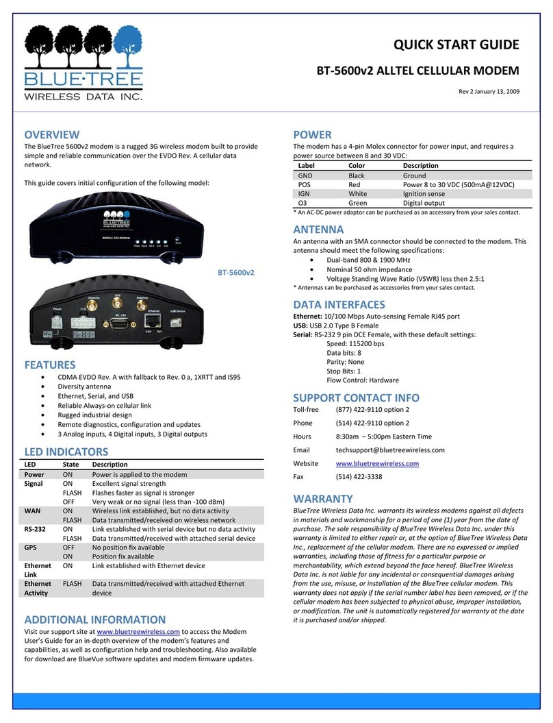
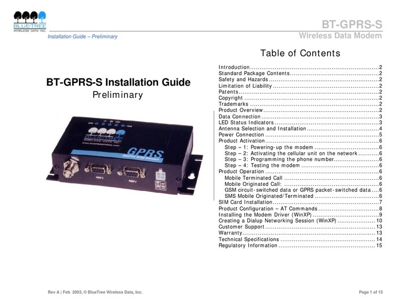
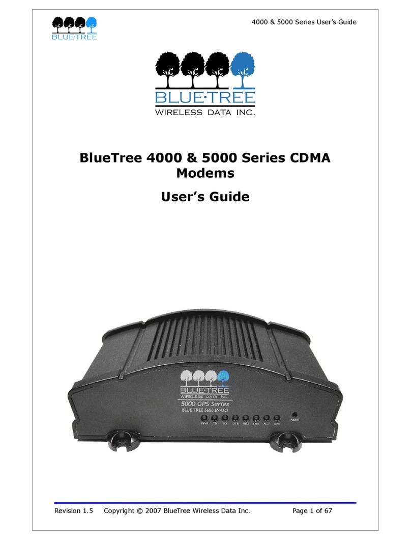
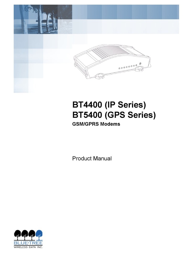
BlueTree BT-2010 User manual

BT-2010
GPRS Standard GPS Modem
Product Manual


V1.5 BlueTree Wireless BT-2010 Product Manual 3
BlueTree Wireless
BT-2010 GPRS Standard GPS Modem
Product Manual
July 2004
GPRSUG-02010

4BlueTree Wireless BT-2010 Product Manual V1.5

V1.5 BlueTree Wireless BT-2010 Product Manual 5
BlueTree Wireless Data, Inc.
2405 46th Avenue
Lachine, QC, Canada H8T 3C9
Tel: +1 (514) 422-9110
Toll Free: 1-877 422-9110
www.bluetreewireless.com
Copyright © 2004 by BlueTree Wireless Data, Inc.
All Rights Reserved
Printed in Canada
BlueTree™, the BlueTree logo, and BlueVue™ are trademarks of
BlueTree Wireless Data, Inc.
All other trademarks are the property of their respective owners.

6BlueTree Wireless BT-2010 Product Manual V1.5
Patents
Portions of this product are covered by some or all of the following
patents:
For BT-2000 or BT-2010 with RIM 1902G module:
US 6,278,442 6,271,605 6,219,694
6,075,470 6,073,318 D445,428
D416,256
Declaration of Conformity
FCC Compliance
Statement (USA) FCC ID: QWV-BTGPRS (for GPRS modems with RIM 1902G module)
FCC ID: QWV-BT2000 (for GPRS modems with Wavecom Q2426
module)
The device complies with Part 15 of the FCC rules. Operation is subject
to the following two conditions:
1. This device may not cause harmful interference.
2. This device must accept any interference received, including
interference that may cause undesired operation.
This equipment generates, uses and can radiate radio frequency energy
and, if not installed and used in accordance with the manufacturer's
instructions, may cause interference harmful to radio communications.
However, there is no guarantee that interference will not occur in a
particular installation. If this equipment does cause harmful
interference to radio or television reception, which can be determined
by turning the equipment off and on, the user is encouraged to try to
correct the interference by one or more of the following measures:
•Reorient or relocate the receiving antenna.
•Increase the separation between the equipment and receiver.
•Connect the equipment into an outlet on a circuit different from
that to which the receiver is connected.
•Consult the dealer or an experienced radio/TV technician for help.
Caution: Unauthorized modifications or changes not
expressly approved by BlueTree Wireless Data, Inc. could
void compliance with regulatory rules, and thereby your
authority to use this equipment.

V1.5 BlueTree Wireless BT-2010 Product Manual 7
Liability Notice
While every effort has been made to achieve technical accuracy,
information in this document is subject to change without notice and
does not represent a commitment on the part of BlueTree Wireless
Data, Inc., or any of its subsidies, affiliates, agents, licensors, or
resellers. There are no warranties, express or implied, with respect to
the content of this document.
Safety
Do not operate the BlueTree Wireless Data BT-2010 modem in areas
near medical equipment, where blasting is in progress, where explosive
atmospheres may be present, or near any equipment that may be
susceptible to any form of radio interference.
Warning: “Antenna must not exceed 5.15 dBi. This
device must be used in mobile configurations. The
antenna(s) used for this transmitter must be
installed to provide a separation distance of at least
30 cm or 12 inches from all persons and must not
be co-located or operating in conjunction with any
other antenna or transmitter. Users and Installers
must be provided with antenna installation
instruction and transmitter operating conditions for
satisfying RF exposure compliance”

8BlueTree Wireless BT-2010 Product Manual V1.5

:
V1.5 BlueTree Wireless BT-2010 Product Manual 9
Contents
Introduction
Welcome.................................................................................. 11
Product Description.................................................................... 11
What you will need .................................................................... 12
Chapter 1: Installing the Modem
Unpacking the Modem................................................................ 15
Installing the SIM Card............................................................... 15
Installing the Modem ................................................................. 16
Installing the Antenna................................................................ 17
Installing the Power Cable .......................................................... 18
Connecting the Data Cables........................................................21
Installing the BlueVue software ................................................... 21
Chapter 2: Activating the Modem
Using BlueVue...........................................................................25
Using Microsoft DUN (Dial-Up Networking).................................... 25
Using AT Commands.................................................................. 27
Chapter 3: Connecting to the Wireless Network
Using BlueVue...........................................................................31
Using Microsoft DUN (Dial Up Networking) .................................... 32
Chapter 4: Using the GPS Features
GPS Features Overview.............................................................. 33
Power-Up and Initialization ......................................................... 33
Using BlueVue...........................................................................34
Tracking GPS location ................................................................ 35
Chapter 5: Troubleshooting
Modem Help ............................................................................. 39
..............................................................................................40
BlueVue Help............................................................................ 40
Appendix A: Warranty and Customer Support
Warranty.................................................................................. 43
Customer Support ..................................................................... 43

:
10 BlueTree Wireless BT-2010 Product Manual V1.5
Appendix B: Reference Information
Modem Reference...................................................................... 45
BlueVue Configuration Options .................................................... 46
BlueVue Basics.......................................................................... 49
Microsoft DUN (Dial-Up Networking) ............................................ 59
AT Commands .......................................................................... 60
GPS Reference .......................................................................... 65
Appendix C: Modem Specifications
Physical Dimensions...................................................................69
Product Specifications ................................................................ 71
Power Consumption................................................................... 72
Certification.............................................................................. 72

Introduction
V1.5 BlueTree WirelessBT-2010 Product Manual 11
Introduction
Welcome Thank you for choosing the BT-2010, BlueTree’s GPRS wireless data
modem with integrated GPS.
Product Description
Modem The rugged BT-2010 modem gives today's mobile organization the
reliable, instant access to information that is critical for its teams.
The unit is a fully integrated GSM modem, which adds wireless GPRS
functionality to remote and mobile applications. Its design makes it
ideal for in harsh environment installations.
The modem is based on RIM’s 1902G or Wavecom’s Q2426 radio
module, and intended for use with a host platform such as a computer
or remote terminal data unit.
The modem provides:
•Compatibility with GSM and GPRS wireless services
•Support for 850 and 1900 MHz frequency bands
•Short Message Service functionality – for both mobile originate as
well as terminate messaging
•GPS location capability so organizations can easily integrate
location-based applications into the workflow.
•Support for TSIP, TAIP and NMEA0183 data output
Software The modem package also includes BlueVue, the BlueTree software that
makes configuring and operating your modem simple and quick. With
BlueVue, modem operators can:

Introduction
12 BlueTree Wireless BT-2010 Product Manual V1.5
•Configure basic operating parameters
•Establish packet data connections
•Monitor status information
The modem is equipped with a Trimble Lassen™ SQ GPS (Global
Positioning System) receiver. The receiver's GPS information is
available to host computers via a serial port.
Host computers can communicate with the GPS receiver using one of
the following data protocols via the AUX serial port.
What you will need Before you install the modem you will need the following:
Cellular antenna To comply to FCC and Industry Canada regulations, cellular antennas
must meet the following specifications:
•Rated gain of 3dB (5.15dBi)
•Minimal cable loss of 0.5dB
•Dual-band 800 & 1900 MHz
•Nominal 50 ohm impedance
•Male TNC connector
•Coil style cellular whip
•Mount designed for a horizontal metal surface of vehicle
Protocol Description
TSIP Trimble Standard Interface Protocol
- Binary, bidirectional
- Default protocol of GPS receiver
TAIP Trimble ASCII Interface Protocol·
- Uses printable character based “sentences”
NMEA 0183 National Marine Electronics Association Protocol
- ASCII character based
- Unidirectional (from receiver only)
Warning: Antenna must not exceed 5.15 dBi. This
device must be used in mobile configurations. The
antenna(s) used for this transmitter must be
installed to provide a separation distance of at least
30cm or 12 inches from all persons and must not be
co-located or operated in conjunction with any other
antenna or transmitter. Users and installers must be
provided with antenna installation instruction and
transmitter operating conditions for satisfying RF
exposure compliance.
Warning: Only approved antennas may be
connected to the modem. Unauthorized antennas,
modifications, or attachments could impair data
quality, damage the modem, or result in the
violation of FCC regulations.

Introduction
V1.5 BlueTree WirelessBT-2010 Product Manual 13
Please contact BlueTree for a list of compatible cellular antennas.
GPS antenna GPS antennas meet the following specifications:
•Active antenna with 3.3 volt preamplifier
•50 Ohm
•SMA connector
•1575 MHz range
BlueTree offers a range of GPS and combination Cellular-GPS antennas.
Please contact Bluetree for more information.
GSM SIM card Available from your local wireless network service provider.
Serial cables You will need two serial cables (one for the data port, the other for the
GPS port) of suitable length to extend from the modem to the
computer, to a maximum length of 25 feet. If you are connecting the
modem to a PC you will also need a DB9 female connector.
Tools and hardware •Small Phillips screwdriver
•Four screws suitable for the material you will mount the modem to.
Available COM ports USB serial adapters
BlueTree has tested USB-Serial adapter solutions from FTDI (http://
www.ftdichip.com) that have worked properly with our modems. Single
USB-Serial adapters and USB-Dual Serial adapters have been tested
and work properly.
More product information can be found at FTDI distributors websites
(http://www.ftdichip.com/FTDisti.htm).
Checking for port conflicts
If you are connecting the modem to a PC, confirm that the computer
does not have any software loaded that could interfere with the COM
port that will be designated for the modem.
For example, HotSync - software used for communicating with the
PalmPilot can occupy the COM port even if the PC does not have
PalmPilot connected to that COM port.
Check any software that loads when your computer starts up, any
software that appears as an icon on your Windows task bar, and disable
or close any applications that normally use a COM port.
Is another modem installed on the PC? Older internal modems can
cause COM port conflicts. PC Card (PCMCIA) modems in laptops can
switch the COM port number of your built-in COM port.

Introduction
14 BlueTree Wireless BT-2010 Product Manual V1.5

Chapter 1: Installing the Modem
V1.5 BlueTree Wireless BT-2010 Product Manual 15
Chapter 1: Installing the Modem
Installing the modem is a seven-step process:
1. Unpack the modem
2. Install the SIM card
3. Install the modem
4. Install the antenna
5. Install the power cable
6. Connect the data cables
7. Install the BlueVue software (optional)
Unpacking the
Modem When the modem arrives, check that the package contains the
following items:
•BT-2010 modem
•15-foot power cable with 2A inline fuse
•Quick Start Guide
•BlueTree installation CD (includes the Product Manual along with
BlueVue software)
•BlueVue software is available from our web site at http://
www.bluetreewireless.com
If any items from this list are missing, please call our service
department toll-free at 1-877-422-9110.
Installing the SIM
Card Note: Before inserting the SIM card be sure the power cable is disconnected
from the modem. The SIM card will not be detected if inserted with power
applied to the modem.
To install the SIM card:
1. Remove one of the screws on the SIM CARD cover plate, located at
the back of the modem casing.
.
Remove this
screw

Chapter 1: Installing the Modem
16 BlueTree Wireless BT-2010 Product Manual V1.5
Installing the
Modem There are 2 ways to mount the modem:
a) Use the 4 mounting holes (3/16") on the sides of the modem
b) Use the din rail (1.4") on the bottom of the modem
2. Loosen the remaining screw,
then flip the plate over so you can
access the SIM slot.
3. Slide the SIM card (gold on
top) into the slot until you feel it
snap into place.
4. Flip the SIM CARD cover plate
back to its original position,
replace the screw in the open
hole, then tighten both screws.
The SIM card is now installed.

Chapter 1: Installing the Modem
V1.5 BlueTree Wireless BT-2010 Product Manual 17
As shown below, the modem includes four mounting holes.
Installing the
Antenna •Cellular band antennas should be mounted more than 30 cm (12
inches) from other antennas.
•Do not install the antenna in a closed metallic enclosure (such as a
cabinet or the trunk of a car).
•For safety reasons, mount the antenna at least 30 cm (12 inches)
away from the body of a person.
•The length of the antenna cable may affect the signal strength.
Choose the appropriate cable type and length.
To install the cellular band antenna:
1. Thread the antenna cable through the vehicle so the cable can
reach the front plate of the modem.
2. Connect the cable to the TNC connector finger tight. Do not use
tools.
Warning: Antenna must not exceed 5.15 dBi. This
device must be used in mobile configurations. The
antenna(s) used for this transmitter must be
installed to provide a separation distance of at least
30 cm or 12 inches from all persons and must not
be co-located or operated in conjunction with any
other antenna or transmitter. Users and installers
must be provided with antenna installation
instruction and transmitter operating conditions for
satisfying RF exposure compliance.

Chapter 1: Installing the Modem
18 BlueTree Wireless BT-2010 Product Manual V1.5
Choosing the location for the GPS antenna
The antenna receives the GPS satellite signals and passes them to the
receiver. The GPS signals are spread spectrum signals in the 1575 MHz
range and do not penetrate conductive or opaque surfaces. Therefore,
to function, the antenna must be located outdoors with an unobstructed
view of the sky.
To install the GPS antenna:
1. Thread the antenna cable through the vehicle so the cable can
reach the front plate of the modem.
2. Connect the cable to the SMA connector.
Installing the
Power Cable The modem includes a 15-foot power cable with 2A inline fuse.
Power cable connector As shown below, the power cable connects to the modem through a
Molex type connector (MiniFit 4-pin).
Connect the
cable here.
Connect the
cable here.
Connectsto
modem. Connects to
12 volt DC
power supply.

Chapter 1: Installing the Modem
V1.5 BlueTree Wireless BT-2010 Product Manual 19
The ignition sense line (white wire) acts as an ON/OFF power switch.
The modem will turn on when the ignition sense line is set between 8
and 30 volts DC. The modem will turn off if the ignition sense line is
less than 7 volts DC.
Pin designations for the connector are shown below.
Pin Annotation Color Description
1GND Black Ground
2POS Red Power supply input to 30 Vdc
3IGN White Ignition input
4OUT Green Digital output (not connected)

Chapter 1: Installing the Modem
20 BlueTree Wireless BT-2010 Product Manual V1.5
Powering up the modem
Note: Make sure that the antenna is connected to the modem before applying
power.
To connect the power cable:
•Connect the red wire directly to the baterry’s positive (+) terminal
or to a source of 8-to-30Vdc.
•Connect the black wire directly to the battery’s negative (-)
terminal or to ground (GND).
•The white wire must be connected to either:
a) a switch for manually turning on and off the modem,
b) the vehicle’s “Accessory for position 2”, for turning ON the
modem without turning on the engine,
c) the vehicle’s “Accessory for position 3”, for turning ON the
modem only when the engine is turned on.
To test the power connection:
1. Check the modem’s LED indicators.
•If the PWR or Power indicator is turned on or if it flashes, the
modem is powered.
•If the PWR or Power indicator is not turned on, review the
installation procedures or see “Modem Help” on page39.
2. Open Windows HyperTerminal and run the AT commands shown in
“Configuring the HyperTerminal session” on page23.
The Ignition Sense Line
should not be connected
directly to the battery.
This manual suits for next models
1
Table of contents
Other BlueTree Modem manuals
Popular Modem manuals by other brands
SWEEX
SWEEX MO002 - QUICK_START_GUIDE quick guide
Sierra Wireless
Sierra Wireless AirCard user guide

Moxa Technologies
Moxa Technologies OnCell G3100 Series user manual
Telenetics
Telenetics Sunrise Series Modular Nest Installating and operation manual
Raymar
Raymar Myriad MD202T quick start guide
Kathrein
Kathrein DCV 10 operating manual
