BlueTree 4600A User manual

4000 & 5000 Series User’s Guide
BlueTree 4000 & 5000 Series CDMA
Modems
User’s Guide
Revision 1.5 Copyright © 2007 B ueTree Wire ess Data Inc. Page 1 of 67

4000 & 5000 Series User’s Guide
B ueTree Wire ess Data, Inc.
2425 46th Avenue
Lachine, QC, Canada H8T 3C9
Te : +1 (514) 422-9110
To Free: 1-877-422-9110
http://www.b uetreewire ess.com
Copyright © 2007 B ueTree Wire ess Data, Inc.
A Rights Reserved
Printed in Canada
B ueTree™, the B ueTree ogo, and B ueVue™ are trademarks of B ueTree Wire ess Data, Inc.
A other trademarks are the property of their respective owners.
Liability Notice
Whi e every effort has been made to achieve technica accuracy, information in this document
is subject to change without notice and does not represent a commitment on the part of
B ueTree Wire ess Data, Inc., or any of its subsidies, affi iates, agents, icensors, or rese ers.
There are no warranties, express or imp ied, with respect to the content of this document.
Revision 1.5 Copyright © 2007 B ueTree Wire ess Data Inc. Page 2 of 67

4000 & 5000 Series User’s Guide
Declaratio of Co formity
FCC Complia ce a d I dustry Ca ada Stateme t
4200/5200
FCC O9EQ2438
IC 3651C-Q2438
4600/5600
FCC QWV-BTX600
IC 4420A-BTX600
4600A/5600A
FCC QWV-BTX600A
IC 4420A-BTX600A
The device comp ies with Part 15 of FCC ru es and with ICES-003 of Industry Canada Ru es.
Operation is subject to the fo owing two conditions:
This device may not cause harmfu interference.
This device must accept any interference received, inc uding interference that may cause
undesired operation.
This equipment generates uses and can radiate radio frequency energy and, if not insta ed
and used in accordance with the manufacturer's instructions, may cause interference harmfu
to radio communications.
However, there is no guarantee that interference wi not occur in a particu ar insta ation. If
this equipment does cause harmfu interference to radio or te evision reception, which can be
determined by turning the equipment off and on, the user is encouraged to try to correct the
interference by one or more of the fo owing measures:
Reorient or re ocate the receiving antenna.
Increase the separation between the equipment and receiver.
Connect the equipment into an out et on a circuit different from that to which
the receiver is connected.
Consu t the dea er or an experienced radio/TV technician for he p.
War i g: “The antenna gain inc uding cab e oss must not exceed 3 dBi
for operation under part 22 subpart H Ce u ar band and 4 dBi for
operation under part 24 subpart E PCS band. The antenna(s) used for this
transmitter must be insta ed to provide a separation distance of at east
30 cm from a persons and must not be co- ocated or operating in
conjunction with any other antenna or transmitter. End-users must be
provided with specific information required to satisfy RF exposure
requirements.”
Revision 1.5 Copyright © 2007 B ueTree Wire ess Data Inc. Page 3 of 67

4000 & 5000 Series User’s Guide
Table of Contents
Sectio 1: Package Co te ts ................................................................................... 6
Sectio 2: Product Overview ................................................................................... 7
2.1 Introduction ....................................................................................................... 7
2.2 Features ............................................................................................................ 8
2.3 Specifications .................................................................................................... 10
2.3.1 Genera specifications ................................................................................. 10
2.3.2 I/O Specifications ...................................................................................... 11
2.3.3 Power specifications and consumption .......................................................... 12
2.3.4 GPS specifications (5000 series modems on y) ............................................... 13
2.4 Modem Views .................................................................................................... 13
2.5 Indicators Lights (LED) ....................................................................................... 14
2.6 Data Interface Specifications: Seria , Ethernet & USB .............................................. 16
2.6.1 Ethernet Port ............................................................................................ 16
2.6.2 USB Device Port ........................................................................................ 16
2.6.3 Seria Port (DB9) ....................................................................................... 16
Sectio 3: BlueVue Device Ma ager ...................................................................... 17
3.1.1 Connecting to the modem ........................................................................... 17
3.1.2 Software overview ..................................................................................... 19
Sectio 4: Activatio & WAN Setup ....................................................................... 20
4.1 Activation ......................................................................................................... 20
4.1.1 Get an account for the modem .................................................................... 20
4.1.2 Program the account information into the modem .......................................... 20
4.1.3 Confirm the success of activation ................................................................. 21
4.2 WAN Setup ....................................................................................................... 22
4.2.1 Enter the account information ..................................................................... 22
4.2.2 Test the connection .................................................................................... 23
Sectio 5: LAN Setup ............................................................................................ 24
5.1 Ethernet and USB LAN ........................................................................................ 24
5.1.1 LAN configuration ...................................................................................... 24
5.1.2 DHCP server ............................................................................................. 25
5.2 Dia -up Networking (DUN) over seria ................................................................... 27
Sectio 6: IP Networki g Features ........................................................................ 28
6.1.1 Port-forwarding ......................................................................................... 29
6.1.2 DMZ ........................................................................................................ 30
6.1.3 IP Pass-through ......................................................................................... 30
6.1.4 Dynamic IP registration .............................................................................. 31
6.1.5 Password protection ................................................................................... 32
Sectio 7: Serial-IP ............................................................................................... 33
Sectio 8: I/O Ma ageme t .................................................................................. 34
Sectio 9: GPS Setti gs ......................................................................................... 35
Sectio 10: Eve t Reporti g .................................................................................. 37
Sectio 11: Hardware I stallatio ......................................................................... 38
11.1 Ce u ar antenna .............................................................................................. 38
Revision 1.5 Copyright © 2007 B ueTree Wire ess Data Inc. Page 4 of 67

4000 & 5000 Series User’s Guide
11.2 Antenna diversity
............................................................................................................................... 39
11.3 GPS antenna ................................................................................................... 39
11.4 Ethernet cab e ................................................................................................. 40
11.5 USB cab e ....................................................................................................... 40
11.6 Seria cab e ..................................................................................................... 40
11.7 Power source ................................................................................................... 41
11.7.1 Powering up the modem ........................................................................... 42
11.7.2 Testing the power connection ..................................................................... 42
11.8 I/O Cab e Wiring .............................................................................................. 43
11.8.1 Connecting a panic button or a passive on/off sensor to the modem’s digita
input: ................................................................................................................. 44
11.8.2 Connecting an active vo tage source to the modem’s digita input: .................. 45
11.8.3 Turning on and off an externa periphera using a power re ay on the modem’s
digita output: ...................................................................................................... 46
11.8.4 Connecting an ana og gauge or source (0-5Vdc) to the modem’s ana og input: . 47
11.8.5 Connecting an ana og gauge or source (4-20mA) to the modem’s ana og input: 48
11.9 Mounting the modem ....................................................................................... 48
Appe dix A : Firmware Upgrades..........................................................................49
Appe dix B : Se di g AT Comma ds.....................................................................52
Appe dix C : Basic GPS Reporti g i BlueVue Device Ma ager...............................54
Appe dix D : Dial-Up Networki g i Wi dows.......................................................57
Appe dix E : BlueVue Device Ma ager Troubleshooti g.........................................59
Appe dix F : Activatio Troubleshooti g...............................................................63
Appe dix G : Applicatio & Miscella eous Troubleshooti g...................................65
Sectio 12: Warra ty ............................................................................................ 68
Revision 1.5 Copyright © 2007 B ueTree Wire ess Data Inc. Page 5 of 67
4000 & 5000 Series User’s Guide
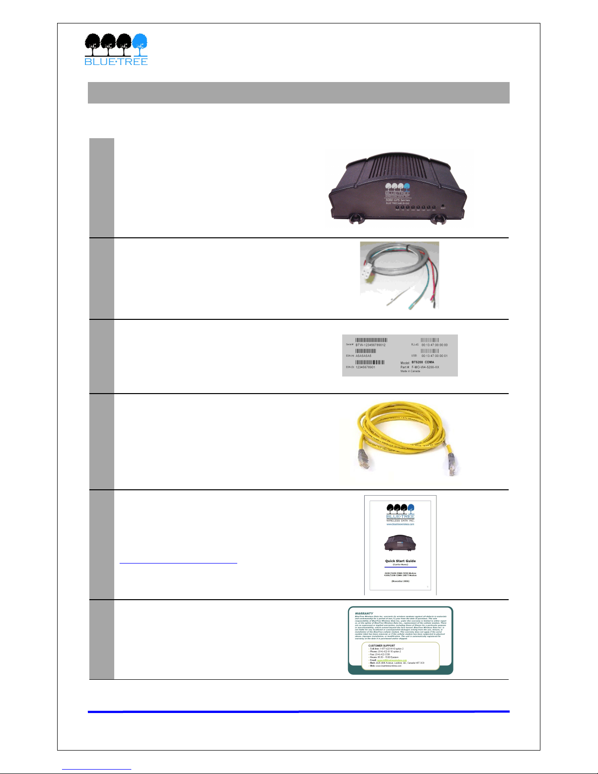
Sectio 1: Package Co te ts
The modem’s retai package contains the fo owing items:
1 4000/5000 Series modem
2 15-foot power cab e with 1A fuse
3 Extra seria number abe
45-foot Ethernet CAT5 cross-over
cab e
5
Quick Start Guide
(a so avai ab e at
www.b uetreewire ess.com)
6 Warranty card
Table 1 - Package Co te ts
Revision 1.5 Copyright © 2007 B ueTree Wire ess Data Inc. Page 6 of 67
4000 & 5000 Series User’s Guide
Sectio 2: Product Overview
2.1 I troductio
The B ueTree 4000 & 5000 series modems are rugged ce u ar modems bui t to provide simp e
and re iab e communication over a CDMA ce u ar data network. They are typica y used in
app ications such as Pub ic Safety, Fie d Force Automation, Asset Tracking, Te emetry, SCADA,
meter reading and WAN backup.
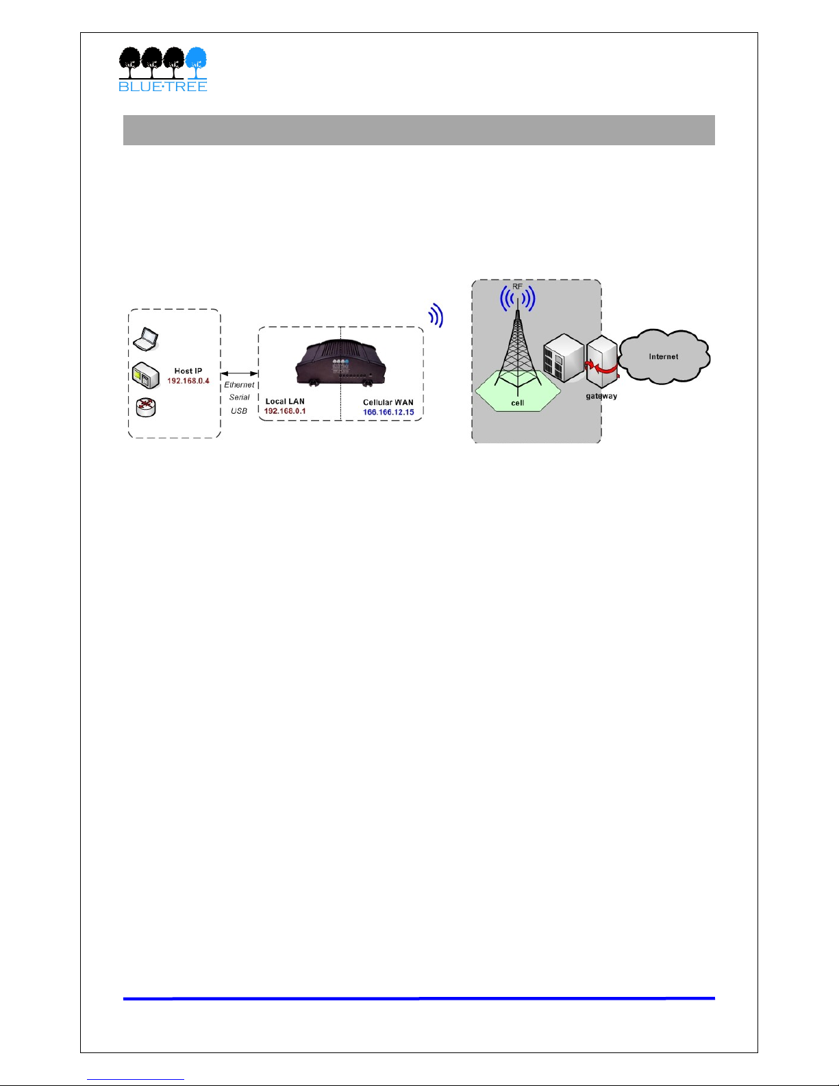
The modem manages two connections at the same time, thus acting as a gateway/router:
•Cellular WAN co ectio : this is the Wide Area Network connection to the ce u ar
network/Internet. The modem can be configured to automatica y and autonomous y
estab ish a packet data connection to the ce u ar carrier and acquire a WAN IP
address.
•LAN co ectio : this is the oca connection between the modem and any device
attached to its seria /Ethernet/USB ports. In the case of Ethernet and USB, the modem
acts as a server and assigns a private LAN IP address to the attached device.
A ternative y, it can perform IP pass-through and assign the WAN IP to the attached
host, thus becoming a fu y transparent actor in the communication process.
The modem then routes packets back and forth between its WAN and LAN connections, thus
a owing the oca y attached device to communicate with remote computers.
Revision 1.5 Copyright © 2007 B ueTree Wire ess Data Inc. Page 7 of 67
Figure 1

4000 & 5000 Series User’s Guide
2.2 Features
3 differe t data co ectio
i terfaces
Seria /RS-232/COM, Ethernet, and USB
Auto omous & persiste t
co ectio ma ageme t
Fu y integrated TCP/IP protoco s a ow the modem to
connect autonomous y to the packet network (Internet).
This feature enab es capabi ities such as: in-ca
diagnostic, Seria -IP, stand-a one GPS, remote
configuration and remote firmware upgrade.
Network Address
Tra slatio (NAT)
When packets eave a LAN IP and reach the modem, it
performs NATing. The source IP of the packet is modified
to match the modem's WAN IP. When packets come back
from the WAN the modem then performs a reverse NAT.
IP pass-through
The modem can assign its WAN IP address to the attached
host, thus disab ing NAT. The modem remains reachab e
through its reserved TCP and UDP ports.
I -call diag ostic The user can get modem status information whi e in a data
ca , without interrupting the data session
Serial IP
The modem encapsu ates data coming from the seria port
into a TCP or UDP packet and sends it to a remote server
on the packet network. It decapsu ates IP packets coming
from the network and sends raw data to the seria port.
Remote co figuratio
The user can remote y configure or perform remote
diagnostics on the modem using B ueVue Device Manager
or a termina session
Remote firmware upgrade The user can remote y upgrade the modem’s firmware
using B ueVue Device Manager
Password protectio
The modem can be protected from tampering by
requesting the user to enter a password before the
existing modem configuration can be viewed or modified
I tegrated GPS Receiver
Avai ab e on the 5000 series modems on y. A Trimb e GPS
receiver is embedded into the modem for Automatic
Vehic e Location (AVL). The modem can report this
positioning data oca y to any of the oca data interfaces
(seria , Ethernet, or Ethernet-over-USB), and/or remote y
to a predefined server (see stand-a one).
Sta d-alo e GPS
Avai ab e on the 5000 series modems on y. This feature
a ows remote asset tracking by sending GPS data to a
remote server without the need for a c ient app ication
connected to the modem.
Store a d Forward
This feature a ows I/O and/or GPS report preservation. If
a unit oses its WAN connection, the data being co ected
through I/O and/or GPS event reporting wi be stored in
memory and automatica y forwarded when the WAN
connection is estab ished.
Revision 1.5 Copyright © 2007 B ueTree Wire ess Data Inc. Page 8 of 67

4000 & 5000 Series User’s Guide
I puts a d Outputs
Sensors can be connected to the I/O port of the modem (4
digita inputs, 3 digita outputs and 3 ana og inputs). The
modem is capab e of monitoring its digita input sensors
for any change in state and sending a report to a remote
server based on an event trigger. The ana og inputs a ow
monitoring of gradient data sources. The modem's outputs
can be used to remote y trigger re ays.
Eve t Reporti g
The modem can send a report to up to 10 destinations
when a user-defined event is triggered. The modem has
an intuitive embedded Event Reporting Protoco that
automatica y formats the messages reported to the
remote server.
Table 2
Revision 1.5 Copyright © 2007 B ueTree Wire ess Data Inc. Page 9 of 67
4000 & 5000 Series User’s Guide
2.3 Specificatio s
2.3.1 Ge eral specificatio s
CDMA Dual-ba d Supports both North American frequency bands: 800 MHz and
1900 MHz
CDMA
A modems are compatib e with CDMA IS-2000 Ce u ar data
services.
Mode :
4600A/5600A modems support EV-DO Rev.A, EV-DO Rel.0
and 1XRTT
4600/5600 modems support EV-DO Rel.0 and 1XRTT
4200/5200 modems support 1XRTT and IS95
Data Rates
Maximum bandwidth: (depends on service provider)
EV-DO Rev.A: 3.1Mbps downstream, 1.8Mbps upstream
EV-DO Rel.0: 2.4Mbps downstream, 153Kbps upstream
1XRTT: 153Kbps downstream and upstream
IS95: 14Kbps downstream and upstream
Programmi g/Setup B ueVue Device Manager software, AT commands
LED Status
I dicators PWR, TX, RX, DTR, REG, LNK, ACT, and SER/GPS
E closure & Weight
Material: extruded a uminium
Size: 166 mm × 127 mm × 56 mm (6.55” × 5.00” × 2.20”)
Weight: 500g (1.1 bs)
Cellular A te a
Co ectio
4200/5200 modems: TNC Fema e Connector, 50 Ohms
4600/5600 modems: 2x SMA Fema e Connector, 50 ohms
4600A/5600A modems: 2x SMA Fema e Connector, 50 ohms
GPS A te a
Co ectio SMA Fema e Connector (3.3 Vo ts active antenna)
E viro me tal
Specificatio s
Operati g Temperature: -40° to +85° C (-40° to +185° F)
Storage Temperature: -40° to +85° C (-40° to +185° F)
Humidity: 95% non-condensing
Table 3
Revision 1.5 Copyright © 2007 B ueTree Wire ess Data Inc. Page 10 of 67
4000 & 5000 Series User’s Guide
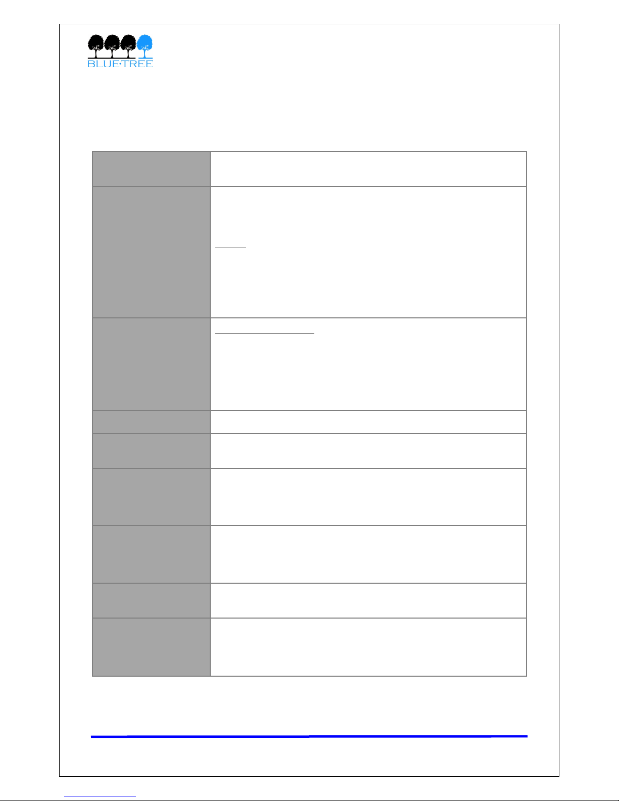
2.3.2 I/O Specificatio s
The modem has 4 digita inputs, 3 ana og inputs and 3 digita outputs for remote contro and
monitoring. The third digita output (O3) is ocated on the power connector for a modems.
The third ana og input (AI3) is not avai ab e on the 4200/5200 mode s.
AI2 GND
AI1 AI3
O2 DI2
O1 DI1
DI4
DI3
Figure 2 – I/Os (Looki g at back of modem)
3x Digital Outputs (O1, O2, O3) – O3 available o Power co ector
Configuration Open Co ector, reference to ground
Abso ute Maximum IDC 500mADC (Vce = 750mVDC)
Abso ute Maximum VDC 30VDC (open circuit)
Abso ute Minimum VDC 0.4VDC (open circuit)
4x Digital I puts (DI1, DI2, DI3, DI4)
Configuration Non-iso ated eve detection, reference to ground
Active eve 1.6VDC to 30VDC
Inactive eve 0VDC to 1.3VDC
Abso ute Minimum VDC 0.3VDC
Abso ute Maximum VDC 33VDC
Leakage IDC at 5VDC 150uADC
3x A alog I puts (AI1, AI2, AI3) – AI3 o ly available o 4600/5600
Configuration Not iso ated input, reference to ground
Reso ution 1024 (ADC 10-bit)
VDC per step 4.8875855mVDC
Fu sca e eve 5VDC
Zero eve 0VDC
Abso ute Minimum VDC -0.3VDC
Abso ute Maximum VDC 8.3VDC
Leakage IDC at 5VDC 265.96 uADC TYPE
Table 4
Revision 1.5 Copyright © 2007 B ueTree Wire ess Data Inc. Page 11 of 67

4000 & 5000 Series User’s Guide
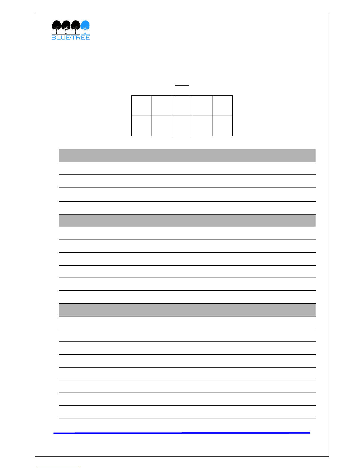
2.3.3 Power specificatio s a d co sumptio
Power is supp ied to the modem via the 4-pin connector on the rear pane . The pins are
described as fo ows:
•Power input to the modem is protected against reverse
po arity and over-vo tage
•The POS input is monitored by the modem as a dedicated ana og input. Used to
monitor the Vo tage
•The IGN input is monitored by the modem as a dedicated digita input
The modem’s power consumption is as fo ows:
Mode Descriptio Approximate co sumptio (mA)
4200 5200 4600 5600 4600A 5600A
Active
(average)
The modem is in a ca and
is transmitting or receiving
data
169 182 179 188 190 200
Active
(peak)
The modem is in a ca and
is transmitting or receiving
data
287 300 300 311 330 340
Id e
The modem is either not in
a ca , or is in one but is
Dormant. The modem is
Dormant after 20s of
inactivity.
49 62 56 67 70 80
Ignition
OFF
The modem is turned OFF
but sti has power from its
POS input. A circuitry is
shut down except for Non-
Vo ati e memory and Rea -
time C ock.
1 1 1 1 1 1
Table 6
Wiring instructions are provided in Section 11: Hardware Insta ation.
Revision 1.5 Copyright © 2007 B ueTree Wire ess Data Inc. Page 12 of 67
Pi Name Descriptio
1 GND Ground
2 POS Power supp y input (8 to 30 Vdc)
3 IGN Ignition sense input – Switches the modem on or off
4 O3 Digita Output 3
Table 5
Table 6
O3 IGN
GND POS
Figure 3 –
Power (Looki g
at back of
modem)

4000 & 5000 Series User’s Guide
2.3.4 GPS specificatio s (5000 series modems o ly)
Ge eral
•L1 frequency (1575.42 MHz)
•C/A code (Standard Positioning Service)
•12-channe
•Continuous tracking receiver
Update rate •TSIP @ 1 Hz
•NMEA @ 1Hz
Accuracy
•Horizonta : <5 meters (50%), <8 meters (90%)
•A titude: <10 meters (50%), <16 meters (90%)
•Ve ocity: 0.06 m/sec.
•PPS (static): ±50 nanoseconds
Acquisitio
Autonomous Operation in Standard Sensitivity Mode:
•Reacquisition: <2 sec. (90%)
•Hot Start: <10 sec. (50%), <13 sec. (90%)
•Warm Start: <38 sec. (50%), <42 sec. (90%)
•Co d Start: <50 sec. (50%), <84 sec. (90%)
Co d Start requires no initia ization.
Warm Start imp ies ast position, time and a manac are saved by
backup power.
Hot start imp ies ephemeris a so saved.
Optiona (COCOM) imits:
•A titude: 18,000 m
•Ve ocity: 515 m/s
Either imit may be exceeded, but not both.
Dy amics •Acce eration: 4g (39.2 m/sec2)
•Motiona jerk: 20 m/sec3
Revision 1.5 Copyright © 2007 B ueTree Wire ess Data Inc. Page 13 of 67
4000 & 5000 Series User’s Guide
Table 7
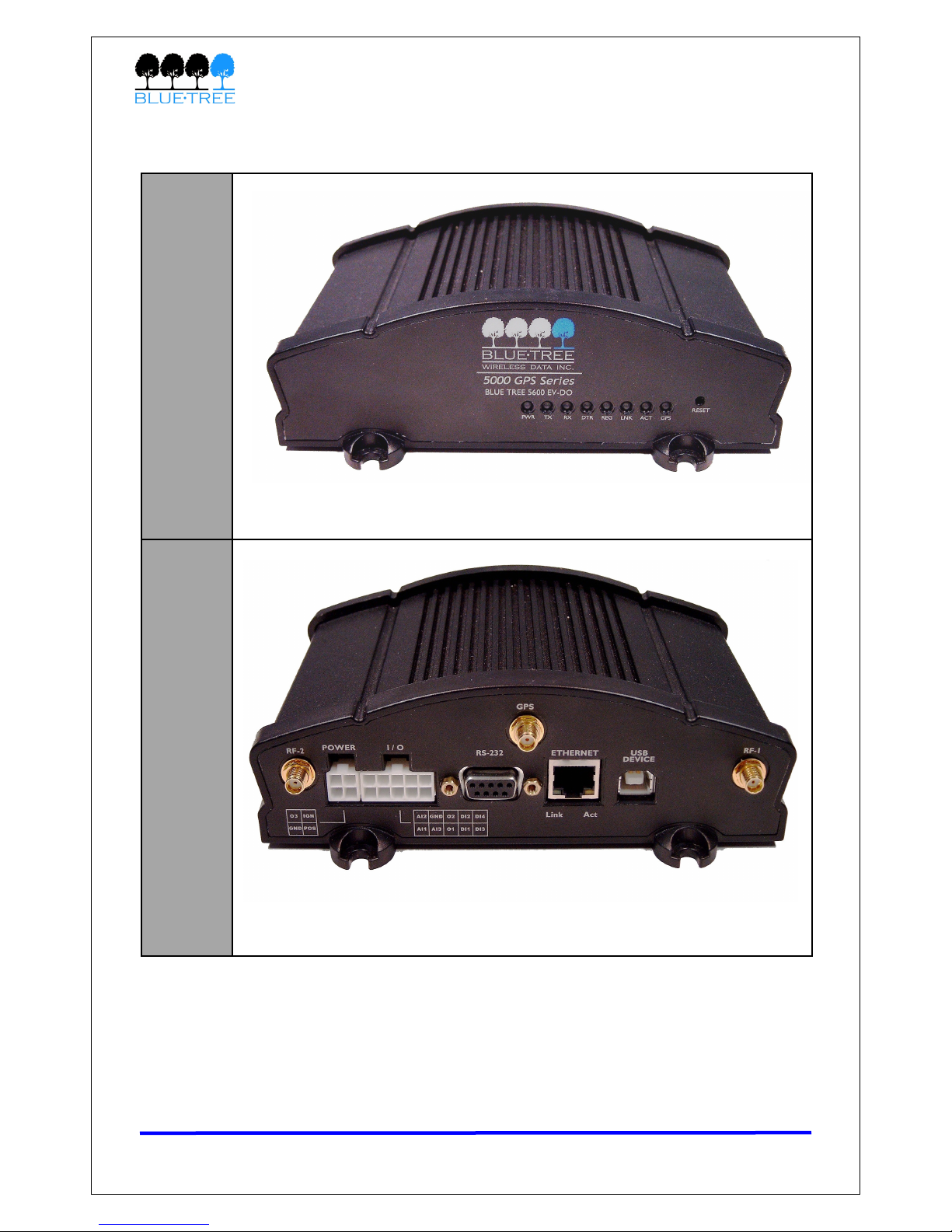
2.4 Modem Views
Fro t
Back
(5600)
Revision 1.5 Copyright © 2007 B ueTree Wire ess Data Inc. Page 14 of 67
Figure 4

4000 & 5000 Series User’s Guide
2.5 I dicators Lights (LED)
The modem has 8 green LEDs on its front pane providing information on the state of the
modem:
LED I dicatio Status Correspo di g State
PWR Power
OFF Modem is powered off
ON Modem is powered on
TX Transmit F ashing Attached termina is transmitting data to
modem via seria port
RX Receive F ashing Attached termina is receiving data from
modem via seria port
DTR Data Termina
Ready
OFF No termina is detected over modem seria
port
ON Termina host is detected over modem seria
port
REG Registration
OFF Radio is off (contact customer support)
F ashing Radio is registered on ce u ar network
ON Radio not registered on ce u ar network
LNK RF ink
OFF Not in a data ca
ON In a data ca (connected to network)
ACT RF activity F ashing Transmitting/receiving data over ce u ar
network
SER
(4000
series)
SER This LED is unused
GPS
(5000
series)
GPS
ON No position fix avai ab e
F ashing Position fix acquired
Table 8
Revision 1.5 Copyright © 2007 B ueTree Wire ess Data Inc. Page 15 of 67
4000 & 5000 Series User’s Guide
2.6 Data I terface Specificatio s: Serial, Ether et &
USB
2.6.1 Ether et Port
The modem's 10/100Mbps Ethernet port is comp iant with the EIA-568 standard, and requires
a crossover cab e to connect to host termina s.
2.6.2 USB Device Port
This is a USB2.0 Device interface on a Type B connector. It offers Ethernet-over-USB
functiona ity using the RNDIS driver.
The B ueTree RNDIS driver must be insta ed before the USB interface can be used. You can
obtain the driver at www.b uetreewire ess.com.
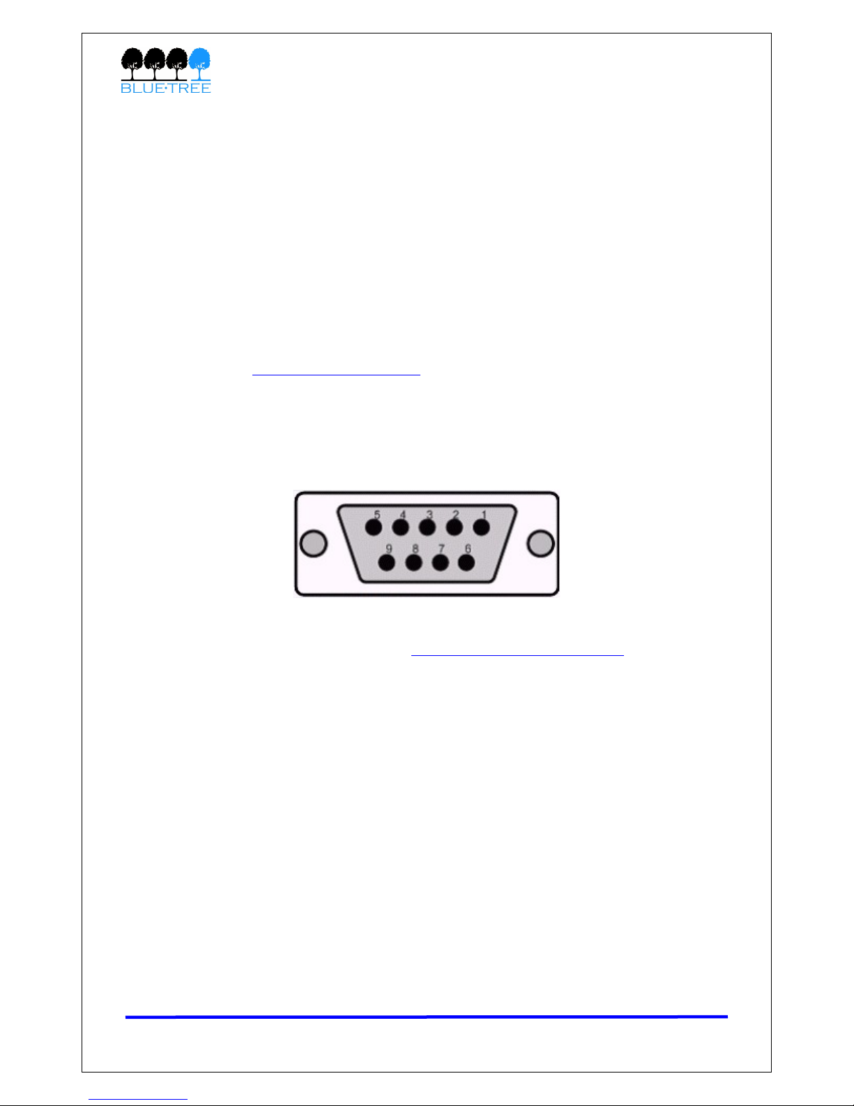
2.6.3 Serial Port (DB9)
The modem’s seria port is an RS232 DCE, comp iant with EIA-232 standard. The connector
used is DB9 fema e and is shown in the i ustration be ow.
Figure 5 – Serial co ector (looki g at back of modem)
For further seria wiring information, refer to Section 11: Hardware Insta ation.
Revision 1.5 Copyright © 2007 B ueTree Wire ess Data Inc. Page 16 of 67
4000 & 5000 Series User’s Guide
Sectio 3: BlueVue Device Ma ager
The 4000/5000 series modems can be configured using B ueVue Device Manager, a software
app ication which is avai ab e as a free down oad at www.b uetreewire ess.com. Later sections
of this guide wi refer to configuration options in this program. For more in-depth information
on using B ueVue Device Manager, refer to the BlueVue Device Manager User's Guide. It can
be accessed from within B ueVue itse f by c icking the He p button, or down oaded separate y
at www.b uetreewire ess.com.
B ueVue Device Manager is a Graphica User Interface for modem configuration and
administration that a ows the user to:
•Activate the modem (program the MDN and MIN) for use on the ce u ar network
•Register the modem on the ce u ar network (WAN Setup)
•Configure operation parameters (such as LAN setup or GPS)
•Monitor diagnostic and status information
•Perform firmware upgrades on the modem
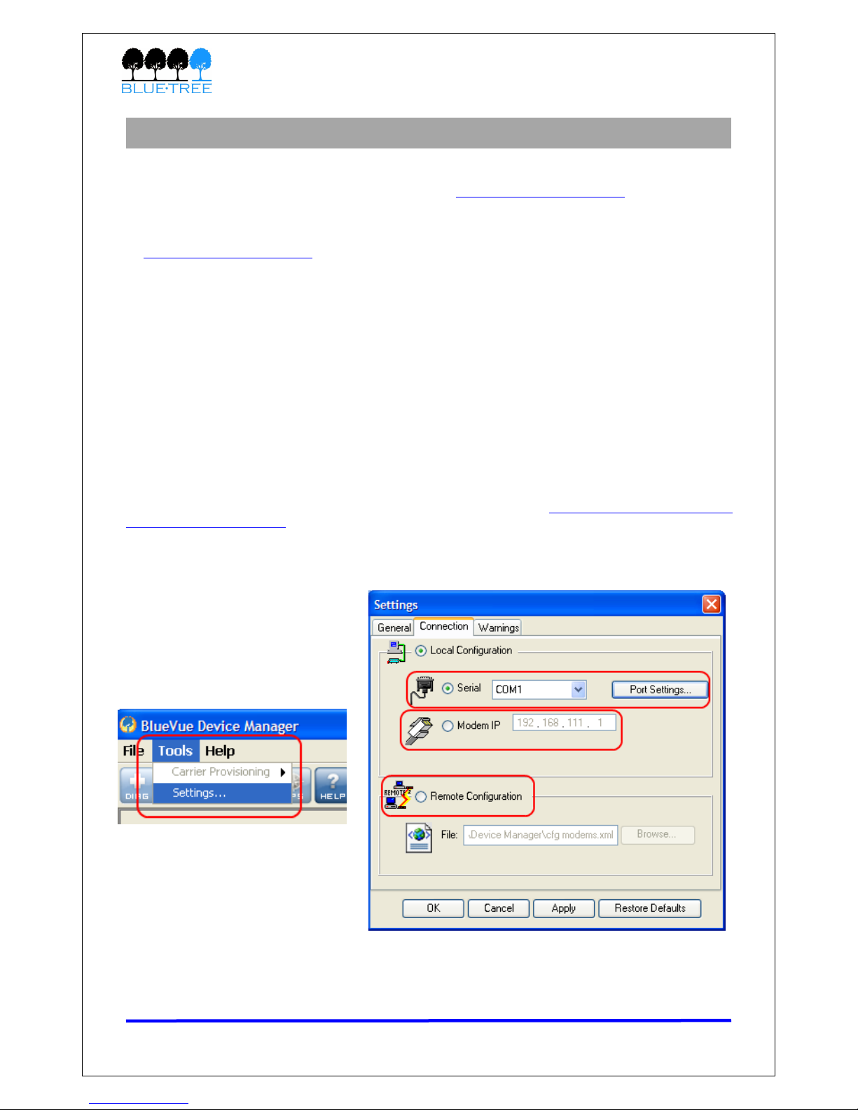
3.1.1 Co ecti g to the modem
Shou d you run into any issues connecting to the modem, refer to Appendix E: B ueVue Device
Manager Troub eshooting.
C ick on Tools > Setti gs > Co ectio tab to se ect the interface that wi connect your PC
to the modem.
Figure 6
Revision 1.5 Copyright © 2007 B ueTree Wire ess Data Inc. Page 17 of 67

4000 & 5000 Series User’s Guide
If usi g a serial cable:
1. Se ect Serial
2. Se ect the COM port in the dropdown ist, then c ick OK
If usi g a Ether et or USB cable:
1. Se ect Modem IP
2. Enter the appropriate modem IP then c ick OK. By defau t, the DHCP-assigned IPs wi
be 192.168.0.1 for Ethernet and 192.168.111.1 for USB. If using USB, the driver
must be insta ed as exp ained in section 2.
If co ecti g to a remote modem:
1. Se ect Remote Co figuratio and c ick OK. A new pane wi open to the eft of
B ueVue Device Manager.
2. Right-click Available Modems in the pane
3. C ick Add…
4. E ter the modem’s i formatio , then c ick OK. The description is optiona .
5. The modem wi be added to the ist of Avai ab e Modems, which wi be saved for easy
access in the future. Double-click the modem ame in order to connect to it.
Figure 7
Revision 1.5 Copyright © 2007 B ueTree Wire ess Data Inc. Page 18 of 67

4000 & 5000 Series User’s Guide
3.1.2 Software overview
Modem Diag ostic
This screen disp ays various technica information pertaining to the modem's state.
Modem Co figuratio
This screen a ows the user to configure the modem to suit the app ication
requirements.
Modem Activatio
This screen is where the user performs ce u ar account activation so that the
modem may connect to the ce u ar network.
Modem WAN Setti gs
The screen a ows the user to set the connection profi e on the modem, such as the
user name and password of the account.
Modem GPS
The screen a ows the user to configure the modem for basic GPS reporting.
(Avai ab e on y for the 5200 and 5600/A modems)
Help
This button opens the BlueVue Device Manager User's Guide, a document that
exp ains every parameter of B ueVue Device Manager in detai .
Revision 1.5 Copyright © 2007 B ueTree Wire ess Data Inc. Page 19 of 67

4000 & 5000 Series User’s Guide
Sectio 4: Activatio & WAN Setup
4.1 Activatio
A modem must be activated before it can be used on the ce u ar network. Here are the steps
to fo ow to activate a modem.
4.1.1 Get a accou t for the modem
Contact a ce u ar service provider or ce u ar dea er and request a CDMA account with the
packet data service option for 1xRTT, 1xEV-DO, or 1xEV-DO Rev. A. The provider wi require
the E ectronic Seria Number (ESN) of the modem. The ESN is ocated on the abe under the
modem as we as on the modem’s box.
The ce u ar service provider wi then provide the fo owing account credentia s:
•Mobile Directory Number (MDN): the 10-digit te ephone number assigned to
your unit, inc uding the area code
•Master Lock Code (MLC/SPC): the 6-digit number representing the Service
Provisioning Lock Code. If one was not provided, assume it is 000000.
•Mobile Statio ID (MIN/MSID/IMSI): the 10-digit or 15-digit number required
for Loca Number Portabi ity; If not provided, assume it is the same as the MDN.
•User Name/Password (Optio al): required for network access in some cases.
IMPORTANT: Ask your cellular service provider whether the carrier blocks
incoming connections. f they do, you will be unable to communicate with the
modem remotely unless you ask the service provider to allow incoming
connections to your application’s TCP and UDP ports. f possible, ask them to open
the following ports as well: TCP 21 (used for firmware upgrades), TCP 5070 (used
by BlueVue Device Manager), and TCP 6070 (used for troubleshooting and AT
command configuration).
4.1.2 Program the accou t i formatio i to the modem
Open B ueVue Device Manager and navigate to ACT (Activatio ). The Quick Start Guide
book et inc uded in the modem package contains a step-by-step wa kthrough for activating the
modem. The Quick Start Guide is a so avai ab e at www.b uetreewire ess.com.
Revision 1.5 Copyright © 2007 B ueTree Wire ess Data Inc. Page 20 of 67
This manual suits for next models
5
Table of contents
Other BlueTree Modem manuals


