4Jumper Settings
The modem has the following jumpers.
Jumper Setting
JP2 Transmit Level
1 & 2 = Transmit signal 0 dBm
2 & 3 = Transmit signal -10 dBm
JP3 Receiver Sensitivity
1 & 2 = -10 to -43 dBm
2 & 3 = 0 to -33 dBm
5Rack-Mount Chassis Modem Connector
The back of the Myriad Rack chassis provides a female, DB-25 serial
data connector for each installed modem. The connector’s pin
assignments correspond to the standard RS-232 pin assignments below.
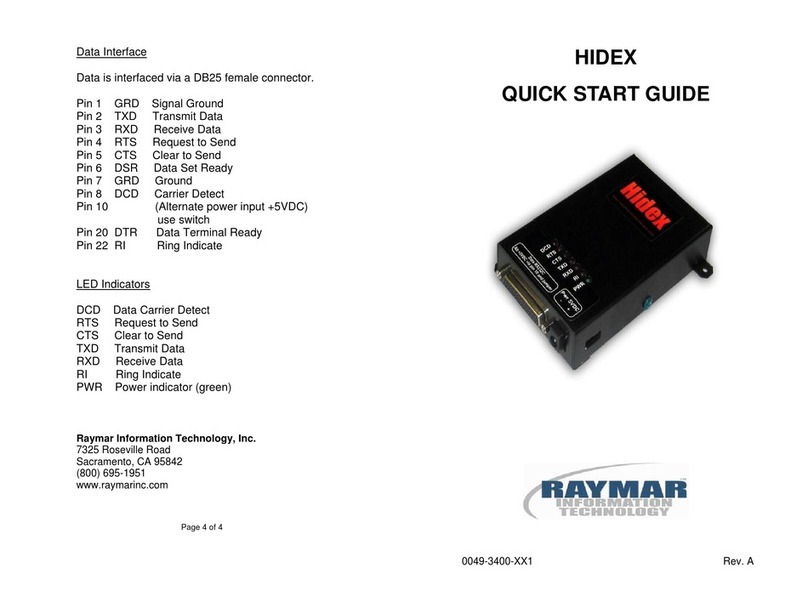
Pin Signal Source
2 Transmit Data DTE
3 Receive Data Modem
4 Ready to Send DTE
5 Clear to Send Modem
6 Data Set Ready Modem
7 Signal Ground ----------
8 Carrier Detect Modem
20 Data Terminal
Ready DTE
S2 Setting
Switch 5 Lease Line 2/4-Wire Configuration
ON = 2 wire
OFF = 4 wire
Switch 6 Received Lease Line Termination
ON = 600 Ohms Termination IN
OFF = No line termination (22K)
Switch 7 Soft Carrier Mode
ON = Soft carrier for 20 ms after RTS
goes from ON to OFF
OFF = Disabled (none)
Switch 8 Test Functions Only (Must be OFF)
6Loopback Configuration
After the modem powers-up, it is in normal mode. Pressing switch SW3
one or more times places it in one of the following modes.
Pressing
SW3 … Causes the
Modem to …
Result
1 time Enter analog loopback
mode All transmitted data loops
back to the Receive Data
port and Transmit Carrier
remains ON.
2 times Enter digital loopback
mode All transmitted data loops
back to the Receive Data
port and Transmit Carrier
remains ON.
3 times Send data in space
mode The Transmit Carrier signal
and remote CD and RxD
signals are all ON.
The table below shows the status of the AL and DL LEDs for these modes.
LEDs
Modes AL DL
Normal OFF OFF
Analog Loopback ON OFF
Digital Loopback OFF ON
Transmit Data in
Space Mode ON ON
Contacting Raymar-Telenetics
To obtain product information or Customer Service, contact Raymar-
Telenetics using any of the following ways:
Web site: www.raymarinc.com / Voice: (916) 783-1951 / Fax: (916) 783-1952
Customer Service is available Monday through Friday, between 8:00 am
and 5:00 pm Pacific Standard Time.
