BLUGUARD SmartBus P900-TI6N User manual

1 V1.1
SmartBus P900-TI6N USER MANUAL
Contents
1.0 INTRODUCTION.................................................................................................................................. 2
2.0 TESTING................................................................................................................................................ 2
3.0 LIMITATIONS...................................................................................................................................... 2
4.0 GLOSSARY............................................................................................................................................ 2
5.0 SUMMARY OF OPERATION............................................................................................................. 2
6.0 TELEPHONY CONTROL DIAGRAM............................................................................................... 2
7.0 LED AND LCD KEYPAD MODEL..................................................................................................... 2
8.0 LED KEYPAD........................................................................................................................................ 2
8.1 UNDERSTAND YOUR KEYPAD INDICATORS.................................................................. 2
8.2 USER PROGRAMMING SUMMARY DIAGRAM ................................................................ 2
8.3 USER PROGRAMMING SUMMARY TABLE....................................................................... 2
8.4 ARMING THE SYSTEM.......................................................................................................... 2
8.4.1 AWAY ARMING.................................................................................................................... 2
8.4.2 DAY ARMING....................................................................................................................... 2
8.4.3 NIGHT ARMING.................................................................................................................. 2
8.4.4 FORCE ARMING................................................................................................................. 2
8.4.5 HOLIDAY ARMING ............................................................................................................. 2
8.4.6 AUTO TIMER ARMING....................................................................................................... 2
8.4.7 TELEPHONE REMOTE ARMING....................................................................................... 2
8.4.8 REMOTE CONTROL ARMING (OPTIONAL) ..................................................................... 2
8.5 DISARMING THE SYSTEM ................................................................................................... 2
8.5.1 KEYPAD DISARMING......................................................................................................... 2
8.5.2 AUTO TIMER DISARMING................................................................................................. 2
8.5.3 TELEPHONE REMOTE DISARMING................................................................................. 2
8.5.4 REMOTE CONTROL DISARMING (OPTIONAL)............................................................... 2
8.6 TURN ON/OFF HOME AUTOMATION POINT.................................................................... 2
8.7 BYPASS ZONE......................................................................................................................... 2
8.8 UN-BYPASS ZONE.................................................................................................................. 2
8.9 VIEW SYSTEM TROUBLE..................................................................................................... 2
8.10 VIEW ALARM MEMORY..................................................................................................... 2
8.11 CHIME MODE........................................................................................................................ 2
8.12 EMERGENCY SITUATION .................................................................................................. 2
8.13 PARTITIONING THE SYSTEM............................................................................................ 2
8.14 ARMING A PARTITIONED SYSTEM ................................................................................. 2
8.14.1 AWAY ARMING 2 PARTITIONS SIMULTANEOUSLY...................................................... 2
8.14.2 AWAY ARMING EITHER 1 PARTITION ........................................................................... 2
8.14.3 FASTKEY AWAY ARMING EITHER 1 PARTITION .......................................................... 2
8.14.4 PARTITION DAY ARMING................................................................................................ 2
8.14.5 PARTITION NIGHT ARMING ........................................................................................... 2
8.14.6 PARTITION FORCE ARMING........................................................................................... 2
8.14.7 PARTITION HOLIDAY ARMING....................................................................................... 2

2 V1.1
SmartBus P900-TI6N USER MANUAL
8.15 PARTITION DISARMING..................................................................................................... 2
8.16 USER CODE ........................................................................................................................... 2
8.17 USER PROGRAMMING MODE ........................................................................................... 2
8.17.1 ACCESS USER PROGRAMMING MODE......................................................................... 2
8.17.2 EXIT USER PROGRAMMING MODE............................................................................... 2
8.17.3 PROGRAM NEW AND CHANGING EXISTING MASTER / USER CODE........................ 2
8.17.4 PROGRAM NEW AND CHANGING EXISTING DURESS CODE..................................... 2
8.17.5 ERASE USER or DURESS CODE...................................................................................... 2
8.17.6 PROGRAM SYSTEM TIMER.............................................................................................. 2
8.17.7 PROGRAM PARTITION 1 OR PARTITION 2 AUTO ARM TIMER................................... 2
8.17.8 TO ERASE PARTITION 1 OR PARTITION 2 AUTO ARM TIMER.................................... 2
8.17.9 PROGRAM PARTITION 1 OR PARTITION 2 AUTO DISARM TIMER ............................ 2
8.17.10 TO ERASE PARTITION 1 OR PARTITION 2 AUTO DISARM TIMER............................ 2
8.17.11 PROGRAM AUTO ON TIMER 1/2/3/4 FOR HOME AUTOMATION.............................. 2
8.17.12 TO ERASE AUTO ON TIMER 1/2/3/4 FOR HOME AUTOMATION............................... 2
8.17.13 PROGRAM AUTO OFF TIMER 1/2/3/4 FOR HOME AUTOMATION............................ 2
8.17.14 TO ERASE AUTO OFF TIMER 1/2/3/4 FOR HOME AUTOMATION............................. 2
8.17.15 PROGRAM PERSONAL TELEPHONE NUMBER 1/2/3/4 .............................................. 2
8.17.16 TO ERASE PERSONAL TELEPHONE NUMBER 1/2/3/4 ............................................... 2
8.18 TESTING THE SYSTEM ....................................................................................................... 2
8.18.1 WALK TEST........................................................................................................................ 2
8.18.2 CMS TEST (Manual Test)................................................................................................... 2
8.18.3 SIREN TEST ....................................................................................................................... 2
8.18.4 STROBE LIGHT TEST ....................................................................................................... 2
8.18.5 BATTERY TEST.................................................................................................................. 2
9.0 LCD KEYPAD ....................................................................................................................................... 2
9.1 UNDERSTAND YOUR KEYPAD INDICATORS (LCD) ...................................................... 2
9.2 USER MENU SUMMARY DIAGRAM (LCD) ....................................................................... 2
9.3 USER PROGRAMMING SUMMARY TABLE....................................................................... 2
9.4 ARMING THE SYSTEM.......................................................................................................... 2
9.4.1 AWAY ARMING.................................................................................................................... 2
9.4.2 DAY ARMING....................................................................................................................... 2
9.4.3 NIGHT ARMING.................................................................................................................. 2
9.4.4 FORCE ARMING................................................................................................................. 2
9.4.5 HOLIDAY ARMING ............................................................................................................. 2
9.4.6 REMOTE CONTROL ARMING (OPTIONAL) ..................................................................... 2
9.4.7 AUTO TIMER ARMING....................................................................................................... 2
9.4.8 TELEPHONE REMOTE ARMING....................................................................................... 2
9.5 DISARMING THE SYSTEM ................................................................................................... 2
9.5.1 KEYPAD DISARMING......................................................................................................... 2
9.5.2 AUTO TIMER DISARMING................................................................................................. 2
9.5.3 TELEPHONE REMOTE DISARMING................................................................................. 2
9.6 TURN ON/OFF HOME AUTOMATION POINT.................................................................... 2
9.7 BYPASS ZONE......................................................................................................................... 2

3 V1.1
SmartBus P900-TI6N USER MANUAL
9.8 UN-BYPASS ZONE.................................................................................................................. 2
9.9 VIEW SYSTEM TROUBLE..................................................................................................... 2
9.10 VIEW ALARM MEMORY..................................................................................................... 2
9.11 CHIME MODE........................................................................................................................ 2
9.12 VIEW ZONE VOCABULARY SETTING ............................................................................. 2
9.13 VIEW HA POINT VOCABULARY SETTING ..................................................................... 2
9.14 EVENT VIEWER.................................................................................................................... 2
9.14 EMERGENCY SITUATION .................................................................................................. 2
9.15 PARTITIONING THE SYSTEM............................................................................................ 2
9.16 ARMING A PARTITIONED SYSTEM ................................................................................. 2
9.16.1 AWAY ARMING 2 PARTITIONS SIMULTANEOUSLY...................................................... 2
9.16.2 AWAY ARMING EITHER 1 PARTITION ........................................................................... 2
9.16.3 FASTKEY AWAY ARMING EITHER 1 PARTITION .......................................................... 2
9.16.4 PARTITION DAY ARMING................................................................................................ 2
9.16.5 PARTITION NIGHT ARMING ........................................................................................... 2
9.16.6 PARTITION FORCE ARMING........................................................................................... 2
9.16.7 PARTITION HOLIDAY ARMING....................................................................................... 2
9.17 PARTITION DISARMING..................................................................................................... 2
9.18 USER CODE ........................................................................................................................... 2
9.19 USER PROGRAMMING MODE ........................................................................................... 2
9.19.1 ACCESS USER PROGRAMMING MODE......................................................................... 2
9.19.2 EXIT USER PROGRAMMING MODE............................................................................... 2
9.19.3 PROGRAM NEW AND CHANGING EXISTING MASTER / USER CODE........................ 2
9.19.4 PROGRAM NEW AND CHANGING EXISTING DURESS CODE..................................... 2
9.19.5 ERASE USER or DURESS CODE...................................................................................... 2
9.19.6 PROGRAM SYSTEM TIMER.............................................................................................. 2
9.19.7 PROGRAM PARTITION 1 OR PARTITION 2 AUTO ARM TIMER................................... 2
9.19.8 TO ERASE PARTITION 1 OR PARTITION 2 AUTO ARM TIMER.................................... 2
9.19.9 PROGRAM PARTITION 1 OR PARTITION 2 AUTO DISARM TIMER ............................ 2
9.19.10 TO ERASE PARTITION 1 OR PARTITION 2 AUTO DISARM TIMER............................ 2
9.19.11 PROGRAM AUTO ON TIMER 1/2/3/4 FOR HOME AUTOMATION.............................. 2
9.19.12 TO ERASE AUTO ON TIMER 1/2/3/4 FOR HOME AUTOMATION............................... 2
9.19.13 PROGRAM AUTO OFF TIMER 1/2/3/4 FOR HOME AUTOMATION............................ 2
9.19.14 TO ERASE AUTO OFF TIMER 1/2/3/4 FOR HOME AUTOMATION............................. 2
9.19.15 PROGRAM PERSONAL TELEPHONE NUMBER 1/2/3/4 .............................................. 2
9.19.16 TO ERASE PERSONAL TELEPHONE NUMBER 1/2/3/4 ............................................... 2
9.19.17 PROGRAM GSM TELEPHONE NUMBER 1/2/3/4.......................................................... 2
9.19.18 TO ERASE GSM TELEPHONE NUMBER 1/2/3/4........................................................... 2
9.19.19 PROGRAM SYSTEM DATE ............................................................................................. 2
9.20 TESTING THE SYSTEM ....................................................................................................... 2
9.20.1 WALK TEST........................................................................................................................ 2
9.20.2 CMS TEST (Manual Test)................................................................................................... 2
9.20.3 SIREN TEST ....................................................................................................................... 2
9.20.4 STROBE LIGHT TEST ....................................................................................................... 2

4 V1.1
SmartBus P900-TI6N USER MANUAL
9.20.5 BATTERY TEST.................................................................................................................. 2
9.21 SYSTEM INFORMATION................................................................................................................. 2
9.22 SYSTEM SETTING............................................................................................................................. 2

5 V1.1
SmartBus P900-TI6N USER MANUAL
The BLUGUARD Control Panel is designed for simple operation yet provides the maximum
protection for you. Please read this manual carefully and follow the instructions contained in this
book. Fill in the system information page and store this manual in a safe place for future
reference.
Your security system consists of a main control panel, one or more keypads and home
automation (HA) modules, various sensors and detectors. An enclosure will contain the control
panel, which includes the system electronics and standby battery.
To ensure that your system is functioning, it is important that you test your system weekly. Please
refer to testing procedures section in this manual. If your system does not function properly,
please contact your system installer for services. There is normally no reason for anyone other
than the installer or service professional to have access to the control panel.
Even though BLUGUARD is an advanced security system, it does not 100% guarantee the
protection against burglary, fire or other loses. Any alarm system whether commercial or
residential is subjected to compromise or failure-to-warn for a variety of reasons. These include:
Intruders may gain access through unprotected openings or have the technical
sophistication to bypass an alarm sensor or disconnect an alarm warning device.
Intrusion detectors, smoke detectors and many sensing devices will not operate without
power. Devices powered by AC will not work if there is no AC power supply for any
reason and the back-up battery is missing, dead or improperly installed.
Alarm warning devices such as sirens may not alert people or wake up sleepers if they
are located on the other side of closed or partly closed doors.
Telephone line needed to transmit alarm events from the premise to a central monitoring
station may be out or temporary out of service. Telephone line is subject to compromise
by sophisticated method of attack.
Smoke detector used in conjunction with the alarm system may not sense fire that start
from where smoke cannot reach the detector such as wall, roof or the other side of the
doors. Smoke detector also may not sense a fire on another level of the residence or
building. In general, detectors may not always warn you about fire caused by
carelessness and safety hazards like smoking, violent explosions, escaping gas,
improper storage of flammable material, overloaded electrical circuits, children playing
with matches.
The most common cause of an alarm system not functioning properly when an intrusion
or fire occurs is inadequate maintenance. Therefore, your system should be tested
weekly to ensure all detectors or sensors are working properly.
Installing an alarm system may make you eligible for lower insurance rates but an alarm
system is not a substitute for insurance. Homeowners, property owners and renters
should continue to insure their lives and properties.
1.0 INTRODUCTION
2.0 TESTING
3.0 LIMITATIONS
Note: All information is subject to changes without prior notice.

6 V1.1
SmartBus P900-TI6N USER MANUAL
Alarm Memory
This is the history of the most recent violations that occurred the last time
when an alarm was triggered.
Arm
To set the system into the ARMED mode. In this mode, a zone violation will
activate an alarm condition. If the system is programmed accordingly, it will
cause a reporting code to be sent to the central monitoring station.
Bypass
To deactivate zone. When the panel is ARMED, violation of a bypassed zone
will be ignored.
Chime
A short beep sound from the keypad to indicate a zone is violated.
Day Arm
Instant arming that allows for certain preprogrammed, DAY STAY zones to be
violated while the system is armed. In this mode, an ENTRY delay time will be
given to the user to disarm using the keypad after entering the armed
premises.
Day Stay Zone
Zones that are bypassed automatically when the system is DAY ARMED.
Disarm
To deactivate the system. FIRE, PANIC and MEDICAL remain active while
the system is disarmed.
Duress Code
An ambush code which will disarm the system and simultaneously send a
silent distress signal to the central monitoring station.
Entry/Exit Zone
A zone with programmable delay time will allow user to exit the premises after
arming the system and disarm by using the keypad after entering the armed
premises. This zone is generally the last exit point and the first entry point of
the building, i.e. the front door of a house.
Follower Zone
A zone that may be temporary violated during exit delay period or after the
first violation of an ENTRY/EXIT zone. This allows the user access to disarm
the system. A FOLLOWER zone will behave as an instant zone if it is violated
prior to the violation of an ENTRY/EXIT zone.
Force Arm
Arming with exit delay that allows for certain violated zones to be bypassed
temporary. When the violated zones resume, these zones will be protected.
There is an ENTRY delay time in this arming mode.
Home
Automation
(HA)
Optional system expander module that allows you to control different light and
appliances from any keypad, remote telephone, cellular phone. It can also be
programmed to turn on/off light at certain time daily or during alarm condition.
Instant Zone
When the system is armed, any violation of an instant zone will immediately
cause an alarm condition to be registered.
Master Code
Master code is a 4-digit personal identification number that allows you to
enter certain programming mode, arm or disarm the system and remotely
control the system via telephone line.
Night Arm
Instant arming that allows for certain preprogrammed, NIGHT STAY zones to
be violated while the system is armed. In this mode, there is no ENTRY delay
time for the user.
Night Stay Zone
Zones that are bypassed automatically when the system is NIGHT ARMED.
Partitioning
A partitioned system is a single physical security system that provides
independent areas of protection intended for use by independent users.
Remote Control
Arm
Arming with a momentary or latch remote control module. In this mode, it
allows certain violated zones to be bypassed temporary. When the violated
zones resume, the zone will be protected. There is an ENTRY and EXIT
delay time in this arming mode.
User Code
User code is a 4-digit personal identification number that allows you to arm or
disarm the system.
Zone
A specific area of your premises guarded by sensors, which detect violations
of that area.
4.0 GLOSSARY

7 V1.1
SmartBus P900-TI6N USER MANUAL
Intelligent Disarm
[4-digit User Code] + [#]
Intelligent Arming
[4-digit User Code] + [#]
Away Arm
Hold down [1] for 2 seconds
Day Arm
Hold down [2] for 2 seconds
Night Arm
Hold down [3] for 2 seconds
Force Arm
Hold down [4] for 2 seconds
Turn On/Off Home
Automation Point
Hold down [5] for 2 seconds + [HA point numbers 1 to 16]+ [#]
Bypass Security Zone
Hold down [6] for 2 seconds + [zone numbers 1 to 16] +[#]
View System Trouble
Hold down [7] for 2 seconds
View Alarm Memory
Hold down [8] for 2 seconds
Program Chime Zone
Hold down [9] for 2 seconds + [zone numbers 1 to 16] + [#]
Holiday Mode Arming
Hold down [0] for 2 seconds
Activate Fire Alarm
Hold down [F] for 2 seconds
Activate Panic Alarm
LED: Hold down [P] for 2 seconds
LCD: Press [MODE] +[8] + [#]
Activate Medical Alarm
LED: Hold down [M] for 2 seconds
LCD: Press [MODE] +[9] + [#]
Turn On/Off Keypad
Buzzer and Speaker
[MODE] + [6] + [#]
Toggle Chime
Beep/Voice
[MODE] + [7] + [#]
Update Voice Settings to
Keypad
[MODE] + [0] + [#]
Event Viewer
[MODE] + [MODE] + [#] (LCD keypad only)
Remark:
To enter zone number more than 9, press button [F] to represent the ten’s digit.
Example: To enter zone number 15, press [F] + [5].
5.0 SUMMARY OF OPERATION

8 V1.1
SmartBus P900-TI6N USER MANUAL
PARTITION SYSTEM ENABLED
Intelligent Disarm
[4-digit User Code] + [#] + [Partition 1] or [Partition 2]
Intelligent Arming
[4-digit User Code] + [#] + [Partition 1] or [Partition 2]
Away Arm
Hold down [1] for 2 seconds + [Partition 1] or [Partition 2]
Day Arm
Hold down [2] for 2 seconds + [Partition 1] or [Partition 2]
Night Arm
Hold down [3] for 2 seconds + [Partition 1] or [Partition 2]
Force Arm
Hold down [4] for 2 seconds + [Partition 1] or [Partition 2]
Holiday Mode Arming
Hold down [0] for 2 seconds + [Partition 1] or [Partition 2]
TESTING THE SYSTEM
Sensor Walk Test
[MODE] +[1] +[#]
CMS Reporting Test
[MODE] +[2] + [#]
Siren Test
[MODE] + [3] + [#]
Strobe Light Test
[MODE] +[4] + [#]
Battery Test
[MODE] +[5] +[#]
SUMMARY OF OPERATION (CONT.)

9 V1.1
SmartBus P900-TI6N USER MANUAL
Remark:
1. The system will automatically cut off telephone line if the user does not key in any number for
more than 60 seconds or key in wrong master code more than 3 times.
2. Master code, User code 2, User code 3 and user code 4 are Telephone remote access codes.
6.0 TELEPHONY CONTROL DIAGRAM
Call In to System:
# (Terminate Telephone
Reporting Immediately)
2. Force Arm / Disarm
system
1. System Voice Report
on:
- Alarm triggered zone
- System Arm / Disarm
- Zone Open / Alarm / Bypassed
- Siren On / Off / Fail
- AC power status
- Home Automation On / Off
4. ON/OFF
Home
Automation
Point
01 to 16
(HA Point
number)
00 (ON /
OFF All
HA
Points)
Dial
Phone
Number
Wait for
Answer
System Call Out:
System
welcome
note and
voice
menu
3. ON/OFF Siren
01 to 16
(Zone
number)
Answer
Call
5. Bypass/
Unbypass
Zone
[Master
Code] +
[#]
Slow
beeps
[Master
Code] +
[#]
00 (Bypass/
Unbypass
All Zones)
System
voice
report
and voice
menu
0. On-site Listen-in
Control

10 V1.1
SmartBus P900-TI6N USER MANUAL
PAGE 11
PAGE 44
7.0 LED AND LCD KEYPAD MODEL

11 V1.1
SmartBus P900-TI6N USER MANUAL
L
E
D
LED
KEYPAD
8.0 LED KEYPAD

12 V1.1
SmartBus P900-TI6N USER MANUAL
L
E
D
ZONE INDICATORS
(Red)
Indicate the status of
the zones
ARMED INDICATOR
(Red)
The indicator is
illuminated when the
system is armed
POWER INDICATOR
(GREEN)
The indicator is
illuminated when AC
power is present
7 VIEW TROUBLE
This key will activate
the VIEW TROUBLE
mode when hold
down for 2 seconds
8 VIEW ALARM
MEMORY
This key will activate
the VIEW ALARM
MEMORY mode when
hold down for 2
seconds
5 TURN ON/OFF HA
POINT
This key will TURN
ON/OFF HA point
when hold down for 2
seconds
MODE
This key will start the
programming or test
mode command
9 CHIME MODE
This key will activate
the CHIME mode
when hold down for 2
seconds
KEYLOCK
INDICATOR
(Orange)
The indicator is
illuminated when the
keypad is locked
MEMORY
INDICATOR
(Orange)
The indicator will slow
flash when the alarm
is triggered
1 AWAY ARM
This key will activate
the AWAY ARM mode
when hold down for 2
seconds
2 DAY ARM
This key will activate
the DAY ARM mode
when hold down for 2
seconds
4 FORCE ARM
This key will activate
the FORCE ARM
mode when hold
down for 2 seconds
3 NIGHT ARM
This key will activate
the NIGHT ARM
mode when hold
down for 2 seconds
FIRE ALARM
This key will activate
the FIRE ALARM
when hold down for 2
seconds
6 BYPASS ZONE
This key will activate
the BYPASS mode
when hold down for 2
seconds
PANIC ALARM
This key will activate
the PANIC ALARM
when hold down for 2
seconds
MEDICAL ALARM
This key will activate
the MEDICAL ALARM
when hold down for 2
seconds
SERVICE
INDICATOR
(Orange)
The indicator is
illuminated when the
system is in trouble
condition
HASH ENTER
This key will confirm
all commands entered
to the system
0 HOLIDAY MODE
This key will activate
HOLIDAY mode when
hold down for 2
seconds
STAR CANCEL
This key will cancel
any unintended
entries
8.1 UNDERSTAND YOUR KEYPAD INDICATORS
13 V1.1
SmartBus P900-TI6N USER MANUAL
L
E
D
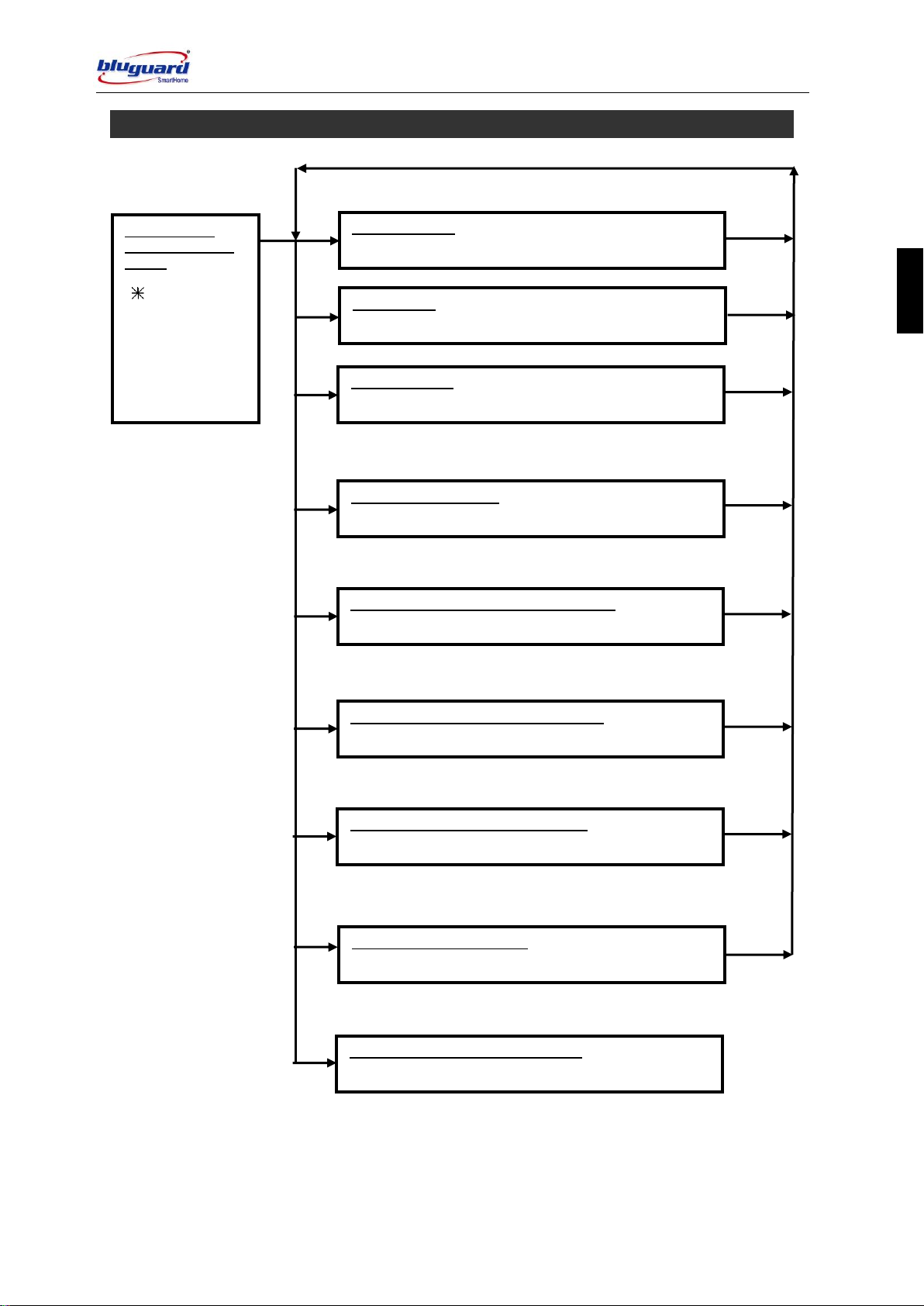
8.2 USER PROGRAMMING SUMMARY DIAGRAM
ENTER USER
PROGRAMMING
MODE
[ ] + [MODE] +
[Master Code] + [#]
Correct code or
step –2 beeps
Wrong code or
step –1 long beep
MASTER CODE
Press [01] + [New Code] + [Re-enter New Code] + [#]
PROGRAM CODES
USER CODE
Press [02 - 15] + [New Code] + [Re-enter New Code] + [#]
DURESS CODE
Press [16] + [New Code] + [Re-enter New Code] + [#]
SYSTEM TIME CLOCK
Press [17] + [Timer in 24-hour format] + [#]
PROGRAM SYSTEM CLOCK
SECURITY AUTO ARM/DISARM TIMERS
Press [18 - 21] + [Timer in 24-hour format] + [#]
PROGRAM SECURITY TIMERS
HOME AUTOMATION ON/OFF TIMERS
Press [22- 29] + [Timer in 24-hour format] + [#]
PROGRAM HOME AUTOMATION TIMERS
REPORTING TELEPHONE NUMBER
Press [30 - 37] + [Reporting telephone number] + [#]
PROGRAM REPORTING TELEPHONE NUMBER
EXIT USER PROGRAMMING MODE
Press [MODE] + [#]
EXIT USER PROGRAMMING MODE
PROGRAM SYSTEM DATE
Press [38] + [Date (DDMMYY)] + [#]
PROGRAM SYSTEM DATE

14 V1.1
SmartBus P900-TI6N USER MANUAL
L
E
D
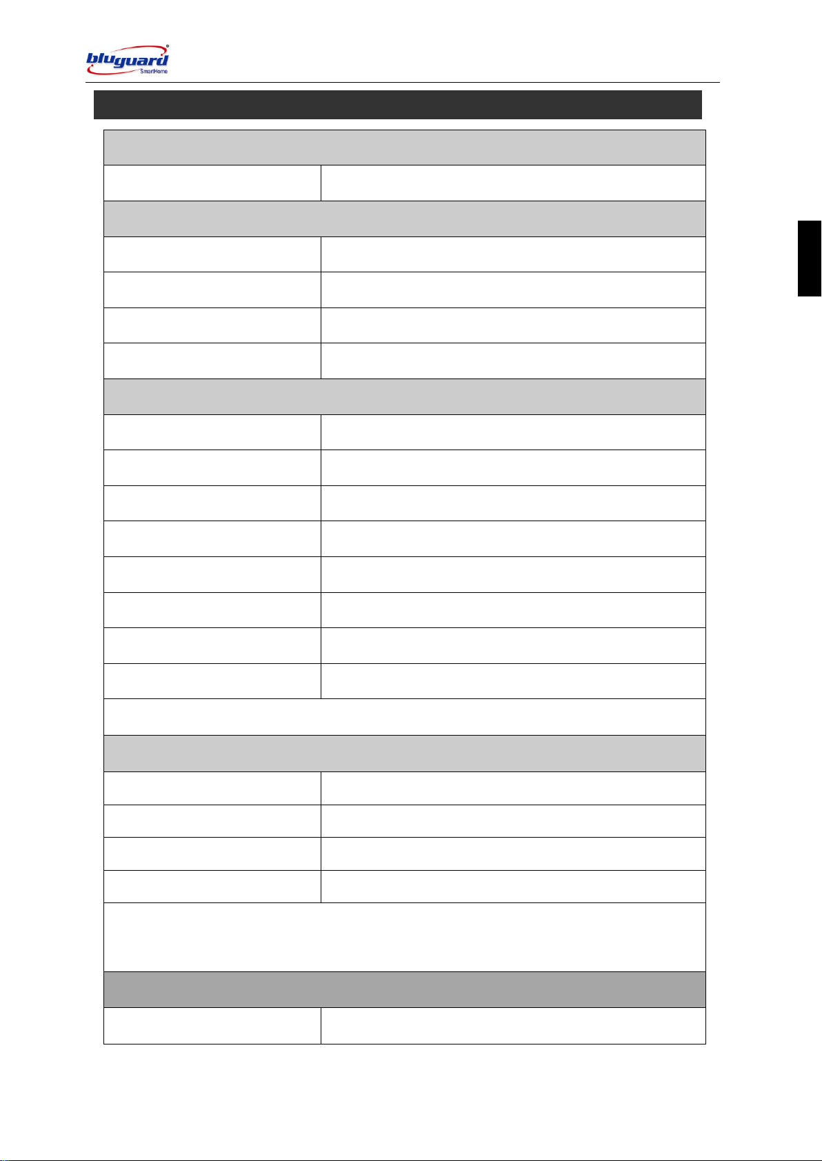
Access User Programming
Mode
[] + [MODE] + [4-digit Master Code] + [#]
Exit User Programming Mode
[MODE] + [#]
Program New or Change Existing
Master Code 01
[01] + [New Master Code] + [Re-enter New Master Code] +
[#]
Program New or Change Existing
User Code 2
[02] + [New User Code] + [Re-enter New User Code] + [#]
User Code 3
[03] + [New User Code] + [Re-enter New User Code] + [#]
User Code 4
[04] + [New User Code] + [Re-enter New User Code] + [#]
User Code 5
[05] + [New User Code] + [Re-enter New User Code] + [#]
User Code 6
[06] + [New User Code] + [Re-enter New User Code] + [#]
User Code 7
[07] + [New User Code] + [Re-enter New User Code] + [#]
User Code 8
[08] + [New User Code] + [Re-enter New User Code] + [#]
User Code 9
[09] + [New User Code] + [Re-enter New User Code] + [#]
User Code 10
[10] + [New User Code] + [Re-enter New User Code] + [#]
User Code 11
[11] + [New User Code] + [Re-enter New User Code] + [#]
User Code 12
[12] + [New User Code] + [Re-enter New User Code] + [#]
User Code 13
[13] + [New User Code] + [Re-enter New User Code] + [#]
User Code 14
[14] + [New User Code] + [Re-enter New User Code] + [#]
User Code 15
[15] + [New User Code] + [Re-enter New User Code] + [#]
Program New or Change Existing
Duress Code
[16] + [New User Code] + [Re-enter New User Code] + [#]
8.3 USER PROGRAMMING SUMMARY TABLE
15 V1.1
SmartBus P900-TI6N USER MANUAL
L
E
D
Program System Timer
System Clock
[17] + [Current Time in 24-hour Format] + [#]
Program Security Timers
Partition 1 Auto Arm Timer
[18] + [Partition 1 Security Auto ARM Timer] + [#]
Partition 1 Auto Disarm Timer
[19] + [Partition 1 Security Auto DISARM Timer] + [#]
Partition 2 Auto Arm Timer
[20] + [Partition 2 Security Auto ARM Timer] + [#]
Partition 2 Auto Disarm Timer
[21] + [Partition 2 Security Auto DISARM Timer] + [#]
Program Home Automation Timers
Home Automation Auto ON
Timer 1
[22] + [Home Automation Auto ON Timer 1] + [#]
Home Automation Auto OFF
Timer 1
[23] + [Home Automation Auto OFF Timer 1] + [#]
Home Automation Auto ON
Timer 2
[24] + [Home Automation Auto ON Timer 2] + [#]
Home Automation Auto OFF
Timer 2
[25] + [Home Automation Auto OFF Timer 2] + [#]
Home Automation Auto ON
Timer 3
[26] + [Home Automation Auto ON Timer 3] + [#]
Home Automation Auto OFF
Timer 3
[27] + [Home Automation Auto OFF Timer 3] + [#]
Home Automation Auto ON
Timer 4
[28] + [Home Automation Auto ON Timer 4] + [#]
Home Automation Auto OFF
Timer 4
[29] + [Home Automation Auto OFF Timer 4] + [#]
Remark: All programmed timer must be in 24-hour format e.g. 7 am = 07 00, 8 pm = 20 00.
Program Reporting Telephone Number
Program Fixed Line Personal
Telephone Number 1
[30] + [Fixed-line Personal Telephone Number 1] + [#]
Program Fixed Line Personal
Telephone Number 2
[31] + [Fixed-line Personal Telephone Number 2] + [#]
Program Fixed Line Personal
Telephone Number 3
[32] + [Fixed-line Personal Telephone Number 3] + [#]
Program Fixed Line Personal
Telephone Number 4
[33] + [Fixed-line Personal Telephone Number 4] + [#]
Remark: Button “P” on the keypad is representing a “PAUSE” key of 5 seconds duration,
Button “M” on the keypad is representing a “” key of telephone system.
Program Reporting Telephone Number (OPTIONAL GSM Module)
Program GSM Personal
Telephone Number 1
[34] + [GSM Personal Telephone Number 1] + [#]
USER PROGRAMMING SUMMARY TABLE (CONT.)

16 V1.1
SmartBus P900-TI6N USER MANUAL
L
E
D
Program GSM Personal
Telephone Number 2
[35] + [GSM Personal Telephone Number 2] + [#]
Program GSM Personal
Telephone Number 3
[36] + [GSM Personal Telephone Number 3] + [#]
Program GSM Personal
Telephone Number 4
[37] + [GSM Personal Telephone Number 4] + [#]
Remark: Button “P” on the keypad is representing a “PAUSE” key of 5 seconds duration,
Button “M” on the keypad is representing a “” key of telephone system.
Program System Date
System Date
[38] + [Date (DDMMYY)] + [#]

17 V1.1
SmartBus P900-TI6N USER MANUAL
L
E
D
There are various options for arming the system
a. Partition Arming
b. Away Arming
c. Day Arming
d. Night Arming
e. Force Arming
f. Holiday Arming
g. Remote Control Arming
h. Timer Auto Arming
i. Telephone Remote Arming
For information on how to ARM Partition system, please refer to PARTITIONING THE SYSTEM
at page 28 (Section 8.13).
[] + [USER CODE] + [#]
(Leave via ENTRY/EXIT Zone)
1. Ensure that all zone indicators are distinguished; if not, check that all protected premises
are closed.
2. Press the [] key to cancel any unintended entries.
3. Enter a valid 4-digit [USER CODE]. If you enter any mistakes, press []key and re-enter
the code followed by [#] key to confirm you command.
4. P1 indicator will illuminate.
5. The keypad audible indicator will sound on and off for the duration of the EXIT delay.
6. Any bypassed zones will be shown by the flashing zone indicators.
7. Leave the premises only via the EXIT/ENTRY zone.
8. During AWAY arming, the telephone line will be supervised hourly. If the telephone line is
disconnected, a new trouble condition will be registered (please refer to View System
Trouble page 24).
9. User will be given an ENTRY delay time to disarm the system when enter the protected
premises via ENTRY/EXIT zone.
10. It is also possible to AWAY arm by simply press and hold down key [1] for 2 seconds.
[1]
(Press and hold down for 2 seconds)
8.4 ARMING THE SYSTEM
8.4.1 AWAY ARMING

18 V1.1
SmartBus P900-TI6N USER MANUAL
L
E
D
[2]
(Press and hold down for 2 seconds)
1. This arming mode is ideal for DAY time arming with user still remains in the protected
premises.
2. In this mode, the system will be armed instantly with certain preprogrammed, DAY STAY
zones bypassed automatically.
3. Ensure that all zone indicators are distinguished; if not, check that all protected premises
are closed.
4. DO NOT open the ENTRY/EXIT zone.
5. Press and hold down key [2] for 2 seconds.
6. P1 indicator will illuminate.
7. The keypad audible indicator will sound 2 beeps to confirm the arming.
8. Any DAY STAY zones will be automatically bypassed (shown by flashing zone
indicators).
9. User will be given an ENTRY delay time to DISARM the system when enter the protected
premises via ENTRY/EXIT zone.
[3]
(Press and hold down for 2 seconds)
1. This arming mode is ideal for NIGHT time arming with user still remains in the protected
premises.
2. In this mode, the system will be armed instantly with certain preprogrammed, NIGHT
STAY zones bypassed automatically.
3. Ensure that all zone indicators are distinguished; if not, check that all protected premises
are closed.
4. DO NOT open the ENTRY/EXIT zone.
5. Press and hold down key [3] for 2 seconds.
6. P1 indicator will illuminate.
7. The keypad audible indicator will sound 2 beeps to confirm the arming.
8. Any NIGHT STAY zones will be automatically bypassed (shown by flashing zone
indicators).
8.4.2 DAY ARMING
8.4.3 NIGHT ARMING

19 V1.1
SmartBus P900-TI6N USER MANUAL
L
E
D
9. There is no ENTRY delay in this arming mode. Any violation on the active zones will
trigger the system instantly.
[4]
(Press and hold down for 2 seconds)
1. In this mode, the system will be armed with EXIT delay time which allows certain violated
zones to be bypassed temporary. When the violated zones resume, the zone will be
protected again.
2. Press and hold down key [4] for 2 seconds.
3. P1 indicator will illuminate.
4. The keypad audible indicator will sound on and off for the duration of the EXIT delay.
5. Any bypassed zones will be shown by the flashing zone indicators.
6. User will be given an ENTRY delay time to DISARM the system when enter the protected
premises via ENTRY/EXIT zone.
[0]
(Press and hold down for 2 seconds)
1. This arming mode is ideal for long away occasion (holiday).
2. In this mode, the system will be AWAY armed. Home Automation points will be random
ON/OFF every hour to simulate occupancy from 7pm to 1am.
3. Ensure that all zone indicators are distinguished; if not, check that all protected premises
are closed.
4. Press and hold down key [0] for 2 seconds.
5. P1 indicator will illuminate.
6. The keypad audible indicator will sound on and off for the duration of the EXIT delay.
7. Any bypassed zones will be shown by the flashing zone indicators.
8. Leave the premises only via the EXIT/ENTRY zone.
9. User will be given an ENTRY delay time to disarm the system when enter the protected
premises via ENTRY/EXIT zone.
10. After disarming, Home Automation random ON/OFF function will be deactivated and the
system will resume to normal Home Automation ON/OFF timers setting.
8.4.4 FORCE ARMING
8.4.5 HOLIDAY ARMING

20 V1.1
SmartBus P900-TI6N USER MANUAL
L
E
D
1. Your system can be programmed to automatically ARM itself according to a programmed
schedule.
2. This arming mode will automatically turn to FORCE ARM mode when the system timer
reaches the preset AUTO ARM time.
3. Please refer to User Programming section –Program Auto ARM Timers.
1. Your system can be remotely ARM from outside the house through any normal DTMF
telephone or GSM hand phone.
2. This arming mode will automatically turn to FORCE ARM mode when the user enter a
correct Master Code through Telephone or hand phone.
3. Please refer to Telephone Control Diagram at page 9 (Section 6.0).
1. This arming mode is ideal for remote control unit or key-switch arming.
2. The system will arm in AWAY arming mode.
3. The system will be armed with EXIT delay time which allows certain violated zones to be
bypassed temporary. When the violated zones resume, the zone will be protected again.
4. Press the remote control button or twist and release the key-switch.
5. The system will be armed instantly. Leave the premises via ENTRY/EXIT zone.
6. P1 indicator will illuminate.
7. The keypad audible indicator will sound 2 beeps to confirm the arming.
8. If programmed to do so, the siren will sound briefly for this remote control arming (please
refer to Installer Programming section –system option setting).
9. User will be given an ENTRY delay time to DISARM the system when enter the protected
premises via ENTRY/EXIT zone.
There are various options for disarming the system:
a. Partition Disarming
b. Keypad Disarming
c. Remote Control Disarming
d. Timer Auto Disarming
8.4.6 AUTO TIMER ARMING
8.4.8 REMOTE CONTROL ARMING (OPTIONAL)
8.5 DISARMING THE SYSTEM
8.4.7 TELEPHONE REMOTE ARMING
Table of contents
Other BLUGUARD Control Panel manuals


