bmcm BP16 User manual

BP16 / BP16-PC
Carrier board (with housing) for measuring amplifiers of the MAL series
Features Applications
•16 DIL sockets for MAL amplifiers •controlling of processes
•37-pole Sub-D input socket •development
•37-pole Sub-D output socket •signal conditioning
•BP16: in external metal housing •sensor adjustment
•BP16-PC: for installation in the PC
Page 1
The BP16/BP16-PC (BackPlane)
features slots for
... 16 measuring amplifiers ...
of the MAL series and of other
manufacturers.
The BP16 is a backplane for am-
plifiers with housing used as an
external device, whereas the
BP16-PC can be integrated in a
PC and connected internally to a
PC measuring card.
The BP16 / BP16-PC provides all
included amplifiers with
... electrically isolated supply ... .
For sensor supply additionally
... 5V, 120mA ...
with electrical isolation are pro-
vided.
The measuring amplifier modules
needed for signal conditioning are
... very reasonable ...
standard amplifiers.
To achieve optimum measuring
results, please see for a good sha-
red potential of the signals to be
measured, as there is no electrical
isolation of the measuring amplifi-
ers.
The input signals are connected at
a 37-pole Sub-D socket. The out-
put signals of the individual meas-
uring amplifiers can also be rea-
ched at an additional 37-pole Sub-
D socket.
The measuring cards of BMC
Messsysteme GmbH have an in-
ternal connection for analog input
channels, so that measuring signals
with short lines can be lead di-
rectly from the BP16-PC to the
measuring system.
As the BP16-PC does not need
much space the complete elec-
tronic equipment for measuring
data acquisition can easily be in-
stalled in portable PCs.
If using the appropriate amplifiers
also multi-conductor technique can
be realized.
1 Block diagram

BP16 / BP16-PC
© BMC Messsysteme GmbH Page 2
2 Assembly
The external version BP16 is installed as an independent measuring amplifier system before a measurement system. If
using a USB measuring system of the meM series for example, the housings of both devices can comfortably be fixed
together at the red frames of the device, so that you get a stable unit.
Afterwards connect the output of the BP16 with the inputs of the measuring system using the short ribbon cable in-
cluded with delivery.
fig. 1 fig. 2
The device is supplied via the power supply connector (9-40V DC) and a power supply unit (e.g. ZU-PW10W) or alter-
natively by the connected measuring system, if providing an auxiliary voltage (see chapter 3.1).
The carrier board BP16-PC is installed in a PC next to a measuring card. Keep in mind to supply the carrier board with
the appropriate measuring amplifiers at the respective channels first before connecting the analog output channels of the
BP16-PC to the internal analog input channels of the bmcm measuring card using the enclosed cable (for assignment
see fig.4).
Sensorik (Kanal 1..16)/
sensors (channel 1..16)
BP16-PC
fig.3 fig.4
Now connect the power supply cable with the 2-pole plug which is next to the analog input plug and at the other side to
the power supply of the PC. Finally mount the card into the PC (see fig. 3).

BP16 / BP16-PC
© BMC Messsysteme GmbH Page 3
3 Connections
All connections of the device are available at the front and the back of the BP16 / BP16-PC.
3.1 Power supply
The assignment of the 3-pole DIN plug is shown in the figure on the right. It is located at
the device front of the BP16. There a power supply unit (e.g. ZU-PW10W) can be at-
tached. The BP16-PC is supplied by the PC power supply via a connecting cable.
The following table displays the different possibilities for power supply. Please see for
the correct configuration of jumpers J17-J2. All required jumpers are located above DIL
socket 2 (see fig. 5).
Power source Supply with Meas. system Jumper configuration Notes
3-pole DIN plug 9-40VDC BP16 J17, J18, J20: open
J19: closed
(default configuration)
electrically isolated,
sensor current max. 120mA
PC power supply 12VDC BP16-PC J17, J18, J20: open
J19: closed
(default configuration)
connecting cable included with
delivery,
sensor current max. 120mA
external 5V BP16, BP16-PC J17, J19, J20: open
J18: closed supply must be stabilized,
sensor supply reduced to 50mA
by connected meas-
urement system usually app. 5V,
100mA BP16, BP16-PC J19: open
J17, J20: closed no electrical isolation,
sensor supply reduced to 50mA
3.2 Analog input channels
The 16 analog input channels are connected at the 37-pole Sub-D IN socket of
the BP16 / BP16-PC (BP16: front of device). For each channel separately the
carrier boards BP16 / BP16-PC can be equipped with measuring amplifiers of
the MAL series, so that all inputs are connectable to the most different sensors
or signals.
The following table and figure show the pin assignment of the 37-pole Sub-D
IN socket:
Pin Sub-D 37 IN socket
1(+), 20(-)
...
16(+), 35(-)
17
18
19
36, 37
Analog In 1
...
Analog In 16
+5V (current output for sensor supply)
Temperature reference input (MAL only)
-
GND for +5V sensor supply
3.3 Analog output channels
The 16 analog output channels are lead out at the 37-pole Sub-D OUT
socket (BP16: back of device). Those are the outputs of the respective
MAL amplifiers or of the bypassed DIL socket.
The following table and figure show the pin assignment of the 37-pole
Sub-D OUT socket:
Pin Sub-D 37 OUT socket
1 .. 16
17
20 .. 35
36
18, 19, 37
Analog Out 1 .. 16
alt. 5V supply by measuring system
analog ground (AGND)
alt. 0V supply by measuring system
-
120
21
22
23
24
25
26
27
28
29
30
31
32
33
34
35
36
37
2
3
4
5
6
7
8
9
10
11
12
13
14
15
16
17
18
19
-In1
-In3
-In2
-In4
-In5
-In6
-In7
-In8
-In9
-In10
-In11
-In12
-In13
-In14
-In15
-In16
AGND
AGN
D
+In1
+In5
+In6
+In7
+In8
+In9
+In10
+In11
+In12
+In13
+In14
+In15
+In16
+5V
TR
n.c.
+In3
+In2
+In4
120
21
22
23
24
25
26
27
28
29
30
31
32
33
34
35
36
37
2
3
4
5
6
7
8
9
10
11
12
13
14
15
16
17
18
19
+Out1
+5Out
+6Out
+7Out
+8Out
+9Out
+10Out
+11Out
+12Out
+13Out
+14Out
+15Out
+16Out
+Out3
+Out2
+4Out
+5V (meas. syst.) 0V (meas. syst.
)
n.c.
n.c. n.c.
AGND

BP16 / BP16-PC
© BMC Messsysteme GmbH Page 4
4 Layout diagram of the BP16 / BP16-PC
The measuring amplifier sockets on the BP16 / BP16-PC are numbered from channel 1 = 1 to channel 16 = 16 .
When mounting the measuring amplifiers on the carrier board please observe their correct alignment!
= PIN 1
fig. 5
4.1 Pin assignment of the DIL sockets when using MAL measuring amplifiers
The pin assignment of the measuring amplifier sockets is illustrated by the figure on the
right and the following table.
For using the appropriate measuring amplifier please refer to the documentation of the
MAL.
It is also possible to combine standard measuring amplifiers of other manufacturers with
the BP16 / BP16-PC, as soldering bridges for the module configuration are included and
accessible from the underside of the board. Here you can make all settings regarding
additional functions (A1+2, V1-3) of the standard measuring amplifiers. For further
information about their pin assignment please see the documentation of your measuring
amplifier.
Pin Name Function Pin Name Function Pin Name Function
1 n.c. - 9 n.c. - 17 n.c. -
2 n.c. - 10 n.c. - 18 n.c. -
3 +EX + sensor supply 11 GND ground 19 n.c. -
4 +IN HI signal input 12 n.c. - 20 n.c. -
5 -IN LO signal input 13 n.c. - 21 n.c. -
6 -EX - sensor supply 14 n.c. - 22 OUT amplifier output (±5V)
7 n.c. - 15 n.c. - 23 TR temp. reference (MAL-THR only)
8 n.c. - 16 -UB neg. supply (-9V) 24 +UB pos. supply (+9V)

BP16 / BP16-PC
© BMC Messsysteme GmbH Page 5
4.2 Using the jumpers
Each DIL socket is provided with two or four plug-in jumpers. Those are numbered according to the number of their
BP16 / BP16-PC DIL socket. The jumpers of one socket have different functions and are distinguished from each other
by an additional letter.
Jumper Function Default factory setting
Jx bypass +IN of socket x closed
Jxb lead out +EX of socket x-1 to 37-pole Sub-D socket open
Jxc bypass -IN of socket x closed
Jxd lead out -EX of socket x-1 to 37-pole Sub-D socket open
If socket x is not supplied with a measuring amplifier, as only voltages are to be measured, this socket has to be by-
passed by closing jumpers Jx and Jxc. Please note that this input then can not be operated differentially. Ex works all
sockets are bypassed.
•Do not use any measuring amplifier on a socket where a jumper is set.
•The pin connectors are very damageable, in case of contact problems replace if necessary.
•Always only close either jumpers Jx, Jxc or Jxb, Jxd. Never close all 4 jumpers at the same time!
If using long cables, 4-wire technique or for precise measurements we recommend to lead out the excitation connec-
tions of the measuring amplifiers to the 37-pole Sub-D socket, in order to avoid interferences. This is achieved by clos-
ing jumpers Jxb and Jxd, which are located at the BP16 / BP16-PC DIL sockets with even numbering. So the excita-
tion connections of channel x-1 are lead out at the 37-pole Sub-D socket replacing the original connections of the fol-
lowing even analog inputs (e.g. +EX1 to pin 2, before: +IN2; -EX1 to pin 21, before: –IN2). In this case the number of
available channels is reduced to 50% at the maximum.
fig.6
The following table shows the pin assignment of the two Sub-D37 sockets, if all excitation connections are used:
Pin Sub-D 37 IN socket
1(+), 20(-)
2(+), 21(-)
3(+), 22(-)
4(+), 23(-)
...
15(+), 34(-)
16(+), 35(-)
17
18
19
36, 37
Analog In 1
excitation voltage for Analog In 1
Analog In 3
excitation voltage for Analog In 3
...
Analog In 15
excitation voltage for Analog In 15
+5V (current output for sensor supply)
temperature reference input
n. c.
analog ground for +5V output
Analog In 2, 4, ..., 14, 16 not available!

BP16 / BP16-PC
© BMC Messsysteme GmbH Page 6
5 Connecting examples for using the BP16 / BP16-PC
5.1 2-wire technique with joint supply
The sensor supplies of the measuring amplifiers
are not lead out to the 37-pole Sub-D socket of
the BP16/ BP16-PC (exception: resistance
measurement as 2-wire measurement).
The sensor supply is provided electrically iso-
lated separately from the measuring amplifiers
on the BP16 / BP16-PC.
5.2 4-wire technique
For 4-wire technique the sensor supplies are used by the rele-
vant measuring amplifier. The advantage is that voltage drops
caused by long cables have no influence on the neighbored
channels. However, in this case only 8 channels can be used.
The sensor supply is taken from the amplifier supply. Please
note, that the total of all sensor currents does not exceed
100mA.
Cable shields can be connected at AGND (analog ground) at
one end only.
5.3 Combined 2- and 4-wire technique
It is also possible to connect the channels mixed: in
2-wire as well as in 4-wire technique. Use the 4-
wire technique (here at channel 15) only where you
need a higher accuracy.
Depending on the respective application you will
profit from the optimum use of the BP16 / BP16-
PC.

BP16 / BP16-PC
© BMC Messsysteme GmbH Page 7
5.4 Supply of 15 strain gage 350Ohm sensors
For more than eight strain gage 350Ωsensors the power of the
5V excitation (pin 17) is not sufficient. In this case we suggest
the following way of connection, as show in the figure to the
right.
Eight channels with 350Ωstrain gage bridges can be supplied via
pin 17 (5V). One channel (e.g. channel 15) is connected in 4-
wire technique (channel 16 is not connected). With its sensor
supply this channel as well as additional 6 strain gage measuring
bridges can be supplied.
5.5 Thermocouple measurement with type K
The MAL-THR module is prepared for thermocouple measurement
with compensation. Therefore a sensor for temperature reference must
be installed at the cold junction. A semi-conductor sensor LM35DZ is
used with an absolute accuracy of ±1C°. The sensor is supplied by the
BP16 / BP16-PC with 5V and produces a reference voltage for all
measuring channels proportional to the cold-junction.
The thermocouples can be extended using a copper wire. Yet in this case the temperature reference ZU-TR must be
moved to the cold junction, too.

BP16 / BP16-PC
© BMC Messsysteme GmbH Page 8
6 Important notes for using the BP16 / BP16-PC
•The BP16 / BP16-PC is only suitable for extra-low voltages, please observe the relevant regulations!
•Only use an electrical isolated power supply unit (with CE).
•All accessible pins are electrostatic devices. Workplace must be conductive during installation.
•The jumpers of the BP16 / BP16-PC are very damageable and not too suitable for use in motion, in case of contact
problems and in steady applications we recommend to solder the jumpers if necessary.
•The BP16 / BP16-PC must only be used in closed housings (for reasons relating to EMC).
•For reasons relating to CE use shielded cables. Connect the shield to ground at one end only. Close open inputs if
possible. ESD voltages on lines may cause malfunction during operation.
•For cleaning use water and mild detergent only. The device is designed to be maintenance-free.
•The device ground and the chassis are electrically connected to the chassis of the PC, which is usually also con-
nected to ground. Be sure to avoid ground loops, since they will cause measuring errors!
•The device must not be used for safety-relevant jobs. With the use of the product the customer becomes manufac-
turer by law and is therefore fully responsible for the proper installation and use of the product. In case of improper
use and/or unauthorized interference our warranty ceases and any warranty claim is excluded.
Do not dispose of the product in the domestic waste or at any waste collection places. It has to be either duly
disposed according to the WEEE directive or can be returned to bmcm at your own expense.
7 Technical data BP16 / BP16-PC (typical at 20°C)
•Sensor supply
Sensor supply at PIN17 of Sub-D37: +5V DC, accuracy ±0.25%, TK 100ppm, electrically isolated
Current: max. 100mA (if supplied with 9..40VDC)
Amplifier supply: app. ±9V max. 100mA, electrically isolated
•General data
Power supply: +9..40VDC or 5V, min. 0.3W, max. 4W
CE standards: EN61000-6-1, EN61000-6-3, EN61010-1; for decl. of conformity (PDF) visit www.bmcm.de
ElektroG // ear registration: RoHS and WEEE compliant // WEEE Reg.-No. DE75472248
Max. permissible potentials: 60V DC acc. to VDE, max. 1kV ESD on lines
Analog connections: 37-pole Sub-D socket for input and output each
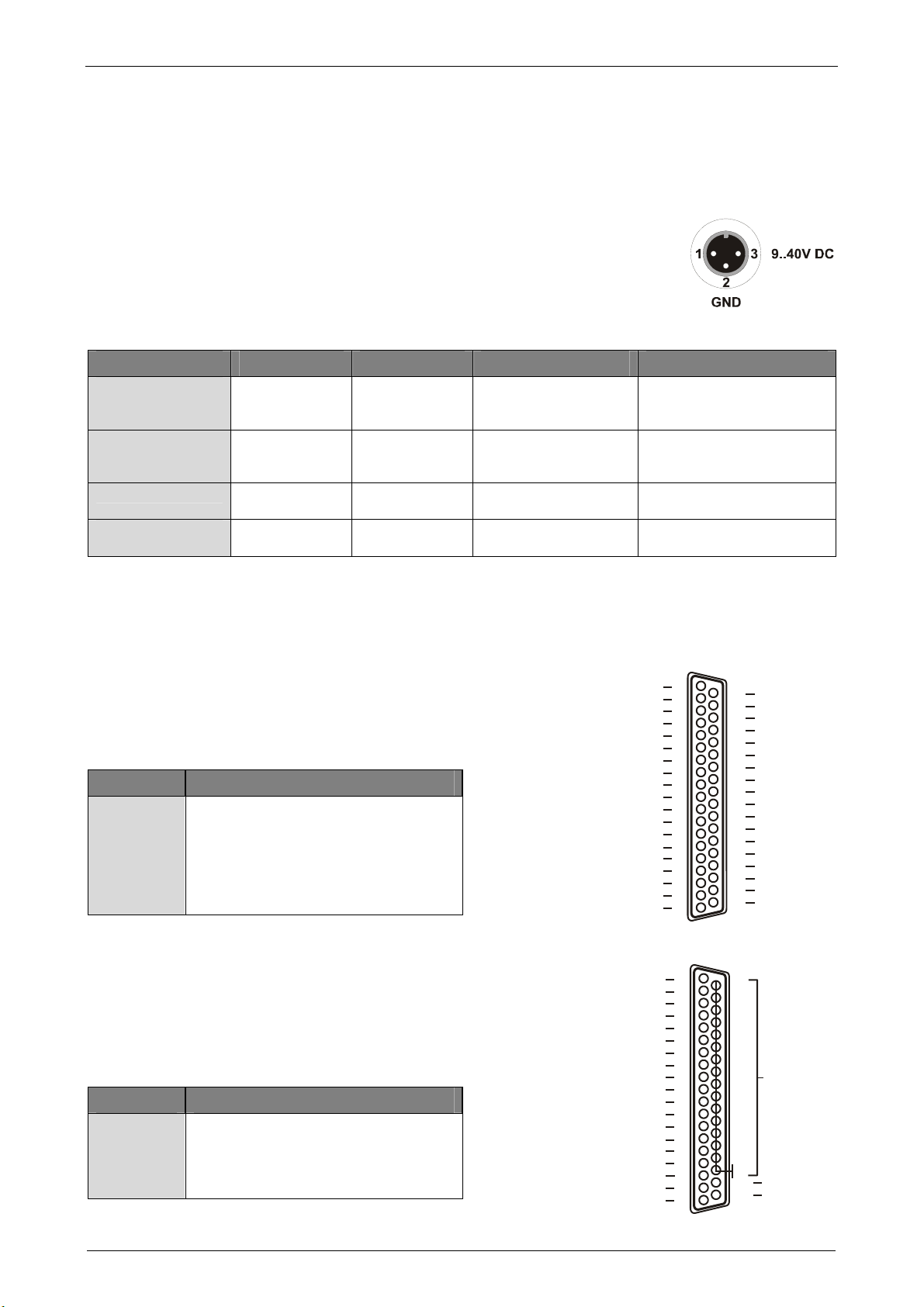
Connection for power supply: BP16: 3-pole DIN plug at the device, BP16-PC: 2-pole pin plug on the board
Temperature range: -25°C..+70°C
Relative humidity: 0-90% (not condensing)
Protection type BP16: IP30
Protection type BP16-PC: IP00
Dimensions BP16: 167 x 113 x 30 mm3
Dimensions BP16-PC: 167 x 100 x 25 mm3
Delivery BP16: BP16 device in aluminum housing, 3-pole coupling for power supply, 37-pole analog out cable
Delivery BP16-PC: BP16-PC board, PC bracket, cable for power supply, analog out cable for internal PC connection
Guarantee: 2 years with effect from sales date, damages at product caused by improper use excluded
•Accessories
Measuring amplifiers: miniature measuring amplifiers and converters of the MAL / MAL-ISO series
Plugs // cables: ZU3DIN, ZU37ST // ZUKA37SB, ZUKA37SS
Connector panels: ZU37BB, ZU37CB, ZU37CO
DIN rail sets: ZU-SCHI
Temperature reference: ZU-TR (LM35DZ) with 37-pole Sub-D plug
Power supply: ZU-PW10W (12V, 1A)
Other: gender changer ZU37SS; wasserdichte Gehäuse ZU-PBOX-PG, ZU-PBOX-LAN
Manufacturer: BMC Messsysteme GmbH. Subject to change due to technical improvements. Errors and printing errors excepted. Rev. 4.1 08/18/2010
This manual suits for next models
1
Table of contents
Other bmcm Carrier Board manuals
Popular Carrier Board manuals by other brands

RTimes
RTimes RTSO-6001B product manual

TQ-Systems
TQ-Systems MBa7x user manual

Diamond Systems
Diamond Systems FLOYD FLD-BB01 user manual

Cytron Technologies
Cytron Technologies Shield-PS2 user manual

Phytec
Phytec phyCORE-PXA270 Hardware manual

ENGICAM
ENGICAM MicroGEA MX6ULL 512MB LCD Getting started manual