BMI 81237 User manual

copyright © 2010 BMI # 81237 RC CAR Flashing lights
Manual Manuel d’instructions
Manual
GB
Manuel d’instructions
F
Thanks for purchasing this product which is easy to install and operate. Four
different fl ashing programs can be installed and we recommend to carefully
read this manual in order to reach the ideal effect you want. We believe your
car will be a very beautiful scene on the racing track with this lightning set.
Contents
1. CAR LED’s : 12pcs
2. CAR LED holders : 12pcs
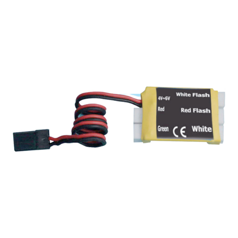
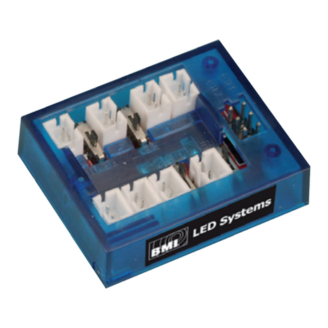
3. Control Box : 1pcs
4. Power connection : Y-cable
5. Control cable with switch
6. Dual tape + LEDs holders
Specifi cations
1. Input Voltage : 4.8V~6.0V
2. Working current : 100mA
3. Dimensions : 47mmx30mmx12mm
4. Led Wire : 35cm
5. Control wire : 28cm
6. Y-cable connecting wire : 28cm
7. Weight : 50g
Set up
1. Drill 5mm for the 3mmLED holders and 7mm for the 5mm LED holders inside the
car body.
2. Slide the LED’s into their respective LED holder.
3. Connect each LED carefully with the plug in the corresponding control box as
illustrated.
4. Stick the control box on the top of the cars chassis with dual tape.
5. Mount the car LED wires on the back of the body and keep enough clearance from
the wheels.
6. Fix (stick eventually) all the wires and check whether they are correctly connected.
Mode
Connect the control cable with switch to the SET-connector on the control box.
Press the control button to select one of the 4 different modes :
1. All the Car LED’s are ON
2. The front LED’s : the white LED’s will fl ash quickly and the blue LED’s will keep ON
The back LED’s : the white LED’s will keep ON, the yellow & Red LED’s will fl ash
quickly.
3. The front LED’s : the white & blue LED’s will fl ash quickly in a loop.
The back LED’s : the white, yellow and red LED’s will fl ash quickly.
4. The front LED’s : the white LED’s is always ON, the blue LED’s are fl ashing quickly.
The back LED’s : the white, yellow and red LED’s are fl ash quickly.
Connection diagram
ATTENTION!
1. Please read carefully the manual
before operating this product. Please
keep this manual by hand for review-
ing anytime
2. Never use a power supply more than
6.0Volt.
3. Take care and don’t drive in water to
avoid short-circuit.
4) Use a 4.8V~6.0V battery as power
supply OR connect the control box to
your receiver. A wrong connection
may cause damage to receiver or
control box.
Nous vous félicitons pour l’achat de ce produit dont l’installation est aisé.
Le boîtier de contrôle permets de programmer 4 modes différents et nous
vous conseillons de lire attentivement les instructions.
L’illumination de votre voiture produira un effet spectaculaire sur le circuit.
Contenu
1. CAR LED’s : 12pcs
2. Supports pour les LEDs : 12pcs
3. Boîtier de contrôle : 1pcs
4. Câble-Y d’alimentation
5. Câble de contrôle avec interrupteur
6. Autocollant double face + supports des LEDs
Spécifi cations
1. Alimentation : 4.8V~6.0V
2. Consommation : 100mA
3. Dimensions : 47mmx30mmx12mm
4. Longueur des câbles LEDs : 35cm
5. Longueur du câble de contrôle : 28cm
6. Longueur du câble-Y de connexion: 28cm
7. Poids : 50g
Instructions
1. Forez des trous de 5mm pour les supports des LEDs de 3mm et des trous de 7mm
pour les supports des LEDs de 5mm, dans la carrosserie.
2. Glissez les LEDs dans leurs supports respectifs.
3. Connectez la fi che de chaque LED dans la prise correspondante du boîtier de
contrôle, suivant le schéma de connexion. Faites ceci avec précaution.
4. Collez à l’aide d’un autocollant double face le boîtier de contrôle sur le châssis de
la voiture.
5. Montez les câbles des LEDs au dos de la carrosserie et tenez les éloigné des roues.
6. Fixez les câbles (autocollant) et vérifi er qu’ils sont correctement connectés.
Mode
Connectez le câble de contrôle au boîtier dans la fi che SET. Poussez le bouton de
l’interrupteur afi n de sélectionner l’un des 4 programmes:
1. Tous les LED’s sont allumés.
2. Les LEDs avants : Les LEDs blancs clignotent tandis que les LEDs blues restent
allumés.
Les LEDs arrières : Les LEDs blancs restent allumés, les LEDs jaunes et rouges
clignotent.
3. Les LEDs avants :Les LEDS blancs et bleus clignotent rapidement en un loop.
Les LEDs arrières : Les LEDs blancs, jaunes et rouges clignotent rapidement.
4. Les LEDs avants : Les LEDs blancs sont allumés et les LEDs bleus clignotent
rapidement.
Les LEDs arrières : Les LEDs blancs, jaunes et rouges clignotent rapidement.
Schéma de connexion
ATTENTION!
1. Veuillez lire attentivement ce manuel
avant tout opération et connexions.
Gardez ce manuel afi n de pouvoir
vous y référer à tout moment.
2. N’utilisez jamais une source d’alimen-
tation supérieure à 6.0 Volt.
3. Ne roulez pas dans de l’eau afi n
d’éviter tout court circuit.
4) Vous pouvez alimenter les LEDs soit
par l’alimentation de votre récepteur
ou par une alimention individuelle de
4V à 6V. mais n’utiliser JAMAIS deux
alimentations en même temps. Une
mauvaise connection peut détériorer
le boîtier de contrôle ou le récepteur.
RC CAR Flashing lights / LED’s clignotants pour voiture RC
Batt.
Or/ou
Rx
# 81237

copyright © 2010 BMI # 81237 RC CAR Flashing lights
Bedienungsanleitung
Handleiding
Bedienungsanleitung
D
Handleiding
NL
Vielen Dank dass Sie sich entschieden haben für dieses BMI-Produkt, das sehr leicht
einzustellen und einzubauen ist. 4 verschiedene Modi können installiert worden und
wir empfehlen Ihnen die Bedienungsanleitung sehr aufmerksam durchzulesen.
Lieferumfang
1. CAR LEDs : 12 St.
2. LED Kunststoffhalter: 12St.
3. Steuereinheit : 1 St.
4. Y-Kabel für Stromversorgung
5. Steuerkabel mit Schalter
6. Doppelseitiges Klebeband + Halterungen LEDs
Technische Daten
1. Eingangsspannung: 4,8~6,0V
2. Stromverbrauch: 100mA
3. Abmessungen: 47mmx30mmx12mm
4. Länge LED-Kabel: 35cm
5. Länge Steuerkabel: 28cm
6. Länge Y-Kabel: 28cm
7. Gewicht: 50g
Instruktionen
1. Bohren Sie 5mm Löcher für die 3mm LED-Halter und 7mm Löcher für die 5mm
LED-Halter an der Innenseite der Karosserie
2. Schieben Sie die LEDs in die Halter
3. Verbinden Sie jeden LED mit seinem Anschluss an der Steuereinheit.
4. Bauen Sie die Steuereinheit mit doppelseitigem Klebeband ein.
5. Legen Sie die Kabel ordentlich und beachten Sie dass die Räder frei drehen können
und es genügend Spiel zwischen Räder und Kabel gibt.
6. Die Kabel mit Tesafi lm an der Innenseite der Karosserie festkleben und kontrollie-
ren die diese ordnungsgemäß installiert sind.
Modi
verbinden sie den Steuerkabel mit Schalter mit seinem Anschluss an der Steuerein-
heit. (SET) und drücken Sie den Knopf um einen Modus auszuwählen Es gibt
4 verschiedene Modi:
1. Alle LED’s brennen.
2. LEDs Vorne: Die Weiße LEDs blinken schnell; die blaue LEDs brennen.
LEDs Heck: Die Weiße LEDs leuchten , die rote und gelbe LEDs blinken schnell. .
3. LEDs Vorne: Die weiße und blaue LEDs blinken schnell in einem Loop.
LEDs Heck: die weiße, rote und gelbe LEDs blinken schnell.
4. LEDs Vorne: Die weiße LEDs brennen, die blaue LEDs blinken schnell.
LEDs Heck: die weiße, gelbe und rote LEDs blinken schnell.
Anschlußschema
Achtung!
1. Bitte lesen Sie die Anleitung auf-
merksam durch und bewahren Sie
diese auf.
2. Niemals höhere Spannungen als
solche im vorgeschriebenen Bereich
zwischen 4,8 und 6,0 V anschließen!
3. Achtung: Nicht ins Wasser und durch
Pfützen fahren: Kurzschlussgefahr.
4) Verwenden Sie eine 4.8V~6.0V Bat-
terie als Stromversorgung ODER ve-
binden Sie die Control Box mit Ihrem
Empfänger. Bei einem Falschen
Anschluss kann der Empfänger oder
der Control Box beschädigt werden.
Bedankt voor de aankoop van dit product, dat zeer eenvoudig te installeren en ge-
bruiken is. Vier verschillende knippermodi kunnen worden geïnstalleerd en wij raden
u aan deze handleiding zorgvuldig door te lezen, teneinde het gepaste lichteffect te
bereiken. Deze lichtset geeft uw modelauto een speciaal effect op de piste.
Inhoud
1. CAR LED’s : 12 St.
2. LED houders : 12 St.
3. Stuureenheid : 1 St.
4. Y-kabel : voeding
5. Stuurkabel met schakelaar
6. Dubbelzijdige tape + LED houders
Specifi caties
1. Ingangsspanning: 4,8V ~ 6.0V
2. Stroomverbruik : 100mA
3. Afmetingen : 47mmx30mmx12mm
4. Lengte kabel met LED : 35cm
5. Lengte Stuurkabel : 28cm
6. Lengte Y-kabel: 28cm
7. Gewicht: 50g
Instructies
1. Boor 5mm gaten voor de 3mm LED-houders en 7mm gaten voor de 5mm LED-
houders aan de binnenzijde van het koetswerk.
2. Schuif de LEDs in hun respectievelijke houders.
3. Verbind elke LED voorzichtig met zijn aansluiting op de stuureenheid zoals
afgebeeld.
4. Maak de stuureenheid vast aan het chassis met dubbelzijdige tape.
5. Leg de kabels van de LEDs over de binnenzijde van het koetswerk. Zorg ervoor er
voldoende speling is tussen wielen en kabels.
6. Maak de kabels uiteindelijk vast met kleefband en controleer of deze goed aange-
sloten zijn.
Modi
Verbind de stuurkabel met schakelaar met zijn aansluiting (SET) op de stuureenheid
en druk vervolgens op de schakelaar om een modus te kiezen. Er zijn 4 verschillende
modi:
1. Alle LEDs branden
2. LEDs voorkant: De witte LED zullen snel knipperen; de blauwe LEDs zullen continu
branden
LEDs achterzijde: De witte LED zullen continu branden, de rode en gele LEDs
zullen snel knipperen.
3. LEDs voorkant: De witte en blauwe LEDs zullen snel knipperen in een loop
LEDs achterzijde: de witte, gele en rode LEDs zullen snel knipperen
4. LEDs voorkant: De witte LED branden continu, de blauwe knipperen snel
LED’s achterzijde: De witte, gele en rode LEDs knipperen snel.
Aansluitschema
Aandacht!
1. Lees de handleiding zorgvuldig, alvo-
rens het product te gebruiken. Houd
deze handleiding bij de hand zodat u
ze telkens opnieuw kan raadplegen.
2. Gebruik nooit een spanningsbron,
groter dan 6V.
3. Let op en rijd niet in water, teneinde
kortsluiting te vermijden.
4) Gebruik een 4.8V~6.0V batterij als
stroombron OF verbind de control
box met uw ontvanger. Verkeerd
aansluiten kan ontvanger of Control
box beschadigen.
RC LED Blinker für Modellautos
RC LED Knipperlichten voor modelauto’s
Batt.
Oder/of
Rx
# 81237
Other BMI Remote Control manuals
Popular Remote Control manuals by other brands

Complete Control
Complete Control RFTX-1 installation manual
Nissin
Nissin AIR 10S COMMANDER Quick manual
Lippert Components
Lippert Components OneControl Unity Board M Series owner's manual
Robe
Robe Anolis E-box Remote Basic user manual

Norman
Norman SmartDial user manual

Pioneer
Pioneer CD-R5/E5 Service manual

Universal Remote Control
Universal Remote Control PHAZR-5 UR5U-9000 operating instructions
Miboxer
Miboxer S1-B manual
Keyspan
Keyspan URM-17A user manual

RCA
RCA RCRPS06GR Manual Del Usuario
Gyration
Gyration GYR3101 user guide
Ambient Technologies
Ambient Technologies RCMT Installation and operating instructions
