BMR SFU 0102 User manual

…when it comes to quality! BMR GmbH
1

2
SFU 0102/0202 F equency Conve te

…when it comes to quality! BMR GmbH
1
Issue June 2016
7.1 Configu ation via the F ont Keys 10
7.2 Configu ation of otational speed 11
7.3 Sta ting und Stopping the F equency Conve te 12
7.4 Remote Cont olled Configu ation of Di ection of 12
Rotation
7.5 Safety Stop Functions 13
7.6 Cont ol via LED F ont Boa d 14
7.7 Spindle Diag am Set Up on LED F ont Panel 17
6.1 Digital and Analogue Inputs and Outputs 8
6.2 Spindle Powe Output (Standa d Round Connecto 8
6.3 Spindle Powe Output (Clamps) 9
6.4 Mains Supply 9
1 Int oduction 2
2 Desc iption and Featu es 3
3 Block Diag am 4
4 Technical Data 5
5 Safety P ecautions and Wa nings 6
6 Connections, Inte faces and Pinout 7
7 Functions, Commissioning, Ope ation
10
8
Calib ation and Configu ation using Windows Softwa e
18
9
E o s, T ouble-Shooting
19
10
EMC (Elect onic- Magnetic Compatibility)
20
11
Housing Va iants
21
13 Ou Quality Commitment
24

2
SFU 0102/0202 F equency Conve te
1. Int oduction
Depending on its construction, the speed of a three-phase a.c. motor is directly dependent
on the number of poles and the frequency of the network. In a 3ph 380 /50Hz network,
with a 2-pole motor, the rated speed would be 50 U/s * 60 = 3000 Upm.
With d.c. motors (brushless d.c.), the speed is dependent on the voltage applied
Three-phase a.c. motors provide numerous benefits in industry, such as brushless operation,
freedom from wear and tear, favourable capacity/weight ratio, high-speed capability, and
much more. These motors can be used many different application areas, such as milling and
grinding spindles, or with drilling machinery, for example.
D.C. motors have the advantage of a high power efficiency (approx. 85%) when compared
with a.c. motors, but the disadvantage of not quite reaching the torque of an a.c. motor at
low speeds (when starting), nor reaching the high speeds of an a.c. motor. However, the
higher efficiency also means cooling requirements are lower and dimensions can be smaller.
In the aforementioned applications, three-phase a.c. motors are operated using special
control gear – frequency converters. These frequency converters convert the fixed 50 Hz
network into a 3-phase network with variable frequency and voltage. This greatly reduces
the start-up problems and the high starting currents that are inevitable when high-capacity
three-phase a.c. motors are connected to a fixed network. The motor is controlled according
to a special characteristic curve until its rated speed has increased, or it has been stopped.
The SFU 0102/0202 - series frequency converter has been specially designed for use in these
high frequency applications, offering excellent safety, performance and reliability, the result
of years of experience in the design and construction of frequency converters, together with
the use of the latest materials and the most reliable components. It can be used in many
different applications and is as equally suitable for use as a replacement device in existing
systems with older type series as it is in pre-planned applications as a cost-effective solution,
helping to prolong the useful life of tools. In addition, both a.c. and brushless dc motors can
be operated by this high frequency converter.

…when it comes to quality! BMR GmbH
3
2. Desc iption and Featu es
Operation of a.c. and bldc spindles
The frequency converter SFU 0102/0202 allows output f equencies up to 200 Hz /
120,000Upm with 2-pole AC motors and 1000Hz/ 60,000Upm with Bloc-motors.
Output powe ( 250VA-0102 / 400VA-0202 )
The Kernel of the SFU-0302 is a Digital Signal P ocesso (DSP), which generates all output
variables and captures signals.
All parameters, such as current, voltage and frequency, are captured in eal time, and
adjusted by implementing via the Vecto Cont ol according to loading.
The highest efficiency of motors at both low and high f equencies is made possible.
High level of ope ational safety. All operating states such as acceleration, operation at rated
speed, and deceleration, are monitored and critical statuses are intercepted and brought
under control.
T anspa ency: The user is continuously informed of the status of the frequency converter and
the motor / spindle by means of a 4-column plain-text display on the front panel (LED panel
optional).
Cont ol: The frequency converter can be manually controlled and calibrated as required using
6 keys on the front panel.
Individual adaptation to the application in hand and the spindle in use. Up to 16 different
spindle characteristics can be created and stored in the memory of the frequency converter,
or existing characteristics can be modified and adapted to the application.
Dive se cont ol and communication possibilities. for connection to peripheral devices
to - PC , PLC (Programmable Logic Control), CNC (Computer Numeric Control).
St aight-fo wa d and flexible integ ation into existing systems by means of open
configuration of I/O signals for control and configuration:
Control inputs: 1 analogue, 3 digital
Control outputs: 1 analogue, 5 digital (relay)
Galvanic sepa ation of all interfaces from each other and from the network / motor potential
Sho t-ci cuit-p otected
Use -f iendly configu ation and control using optional Windows Software for the PC

4
SFU 0102/0202 F equency Conve te
3. Block Diag am

…when it comes to quality! BMR GmbH
5
4. Technical Data
Output power 0102: 250 A 0202: 400 A
Supply connection
Fuse
230 : 2,5AT
115 : 4,0AT
230 : 3,15AT
115 : 5,0AT
Motor connection
Output voltage max. 36 max. 60
Output current
Over-current
Output frequency
Spindle characteristics
Spindle sensor inputs
Control inputs
Control inputs
Control outputs 1 analogue: 0-10 , galvanically separeted
Control outputs
Interface
Housing dimensions
W x H x D (mm)
Weight
Protection
Operating conditions
230 , 50Hz / 115 , 60Hz
switchable with rotary switch and with exchange of fuse
RS232 galvanically separated, 9600Bd
(Desktop) 290 x 107 x 295
(SSE) 117 x 380 x 270
(19") 480 x 135 x 280 3HE / 84TE
5°C … 40°C / rel. humidity of air max. 85%
PTC, magneto-resistor, logic
IP20
(Desktop) ca. 6 kg
(SSE) ca. 7 kg
(19") ca. 8 kg
5 digital: relay outputs,
24 DC/1000mA, 125 AC/500mA
3 digital: 0- 24, galvanically separeted
1 analogue: 0-10 , galvanically separeted
max 16, stored internally, freely definable
Electronically limited
to be set up for 20s
Desktop: 7-pin: U, , W, PE, 2*PTC, SGND
Connector: Amphenol C16-1 (6+PE) / Binder 693 (6+PE)
or Hirschmann connector
SSE and 19"Rack: 8-pole: U, , W, 2*PE, PTC, FP, SGND Screw
terminals 4mm²
AC: 2.000Hz / 120.000 Upm
DC: 1.666Hz / 100.000 Upm
CAUTION:
To avoid seve e moto / spindle damage,
select co ect moto / spindle cha acte istic!

6
SFU 0102/0202 F equency Conve te
5. Safety-P ecautions and Wa nings
This device produces dangerous electrical voltages and is used for the operation of fast
spinning tools. Because of their high rotational speed, it may be dangerous in case of
improper handling. For this reason, only professionally trained and qualified personnel should
be allowed to work with and setup this device!
Before the first commissioning can be carried out, it should be ensured that the spindle and
the tool are fixed properly, to eliminate all dangers because of uncontrolled movement of the
spindle.
Safety regulations being valid for the country where the device is used, have to be adhered to
where any work is carried out on the device.
Before the device is turned on for the first time, it should be verified, that the connected parts
cannot carry out uncontrolled movements.
The frequency converter must not be operated close to heating devices or magnets or devices
generating strong magnetic fields.
Sufficient air circulation around the converter should be ensured.
Fluids should be prevented from intruding into the housing. If it seems to be happened, the
converter has to be switched off immediately.
The ambient air must not use aggressive, flammable or electrically conductive substances and
should be as free of dust as possible.
All repairs and maintenance on the converter and the relating accessories must be carried out
by skilled personal and with powered off, only. To ensure this, the mains plug should be pulled
out. In doing this, both the terms of regulations for preventing accidents and the general and
national rules for mounting and safety have to be applied.
Do not open this device while it is connected to power supply. There is danger of life!
With opening this unit the period of warranty will be ended.
All people who work with this device should be trained and instructed by their line advanced
technician.
Attention:
Please ve ify that all powe supply voltages a e co ect in pola ity and value.
Attention:
Please ensu e to have the p ope cha acte istic selected, always!
The ope ation of a spindle with a w ong cha acte istic may ha m the spindle
seve ely!
Attention:
In case of eplacing the fuses, please ensu e to use types only, which a e
mentioned in 'Technical Data'!

…when it comes to quality! BMR GmbH
7
6. Connections, Inte faces and Pinouts
Operational parameters and outputs:
The SFU 0102/0202 covers all current important operational parameters and operating data.
Up to 6 digital outputs can be used for signalling and up to 1 analogue values can be output
to the analogue outputs (0-10 ).
Remote Control and Outputs:
6 digital inputs (24 ) and 1 analogue inputs (0-10 ) are available for remote control of the
SFU 0102/0202.
These assignments can be freely configured. Using the optional Windows PC software SFU-
Te minal the above assignments can be easily achieved, providing exceptional flexibility with
each application.
Each operating parameter can be assigned as a signal and each control signal can be
allocated the required I/O pin. In addition, the logic level (high or low active) can be
individually defined.
The same assignment is also possible for the analogue measured data and control data at
the analogue I/O pin.
The standard allocations of operational parameters, their outputs, control signals and inputs,
are listed in the following table.
8
SFU 0102/0202 F equency Conve te
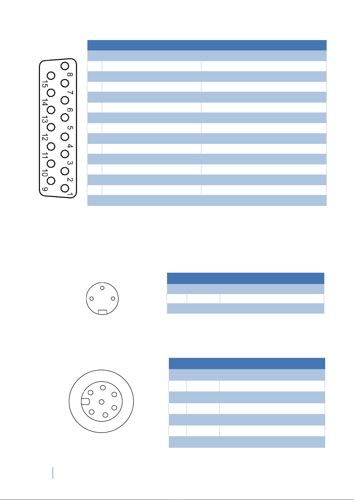
6.1 Digital and Analogue I/Os
(D-SUB 15 female)
6.2 Spindle Output using standa d ci cula connecto
with 3-pin DIN-jack
with 7-pin jack Amphenol C16 (Amphenol C16-1 / Binder 693)
Pin Function
Desc iption
1 common connection for relays
2 Relay 1 (normally open) Rotational Speed Reached
(desired- / actual - value)
3 Relay 2 (normally closed) Supe heat
(converter or spindle)
9 Relay 3 (normally open)
Standstill of Spindle
(desired- / actual - value)
10 Relay 4 (normally closed) Ove load Spindle
6 Relay 5 (normally open) Conve te and Spindle Ready
4
Analogue Output
(depending on Model)
Load Value 0 … 10 = 0 … 100% or Duty
Rotational Speed of Spindle
11 Analogue Input
D ehzahlvo gabe
DC Soll - In (1 / 1000 rpm)
8 Ground
12 Digital Input 1 Sta t / Stop
15 Digital Input 2 Inte lock (Eme gency Stop)
5 Digital Input 3 Reve sing of Di ection of Rotation
13 RxD (RS 232)
14 TxD (RS 232)
7 Impulse magneto resistor Speed sensor
Pin Function
Desc iption
1 U Spindle Phase 1
2PTC PTC-Signal (Spindle temperature)
3 Spindle Phase 2
4 FP Hall-Sensor-Signal
5WSpindle Phase 3
6 SGND Signal- GND for PTC-Signal
7PE Protective Earth
Pin Function Desc iption
1 U Spindle Phase 1
2 Spindle Phase 2
3 W Spindle Phase 3
1
2
3
6
PE
5
4
3
2
1
…when it comes to quality! BMR GmbH
9
with 7-pin jack fo Jäge -Spindles (Hirschmann C164)
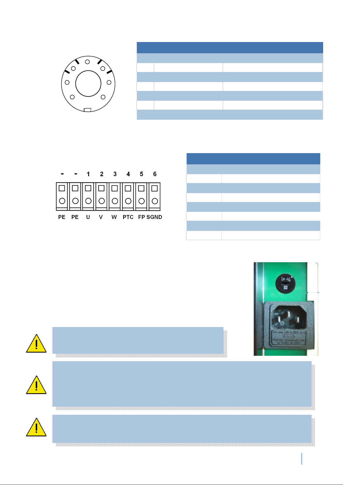
6.3 Spindle Connection with Sc ew Te minals ve sions SSE, 19“
6.4 Mains supply
desktop: 3 pin. standard plug
SSE or 19": Screw terminals, 4mm
2
To adapt the mains supply voltage to 230 and 115 networks
a selection can be done with the help of a rotary switch
Pin Function
Model +5 V Senso
1 NC NC
2 R R
3 S 3 Phases for Spindle S 3 Phases for Spindle
4 T T
5 + PTC + 5V
6 + Hall Sensor + Hall Sensor
7 Signal Ground Signal Ground
Function
Desc iption
PE Protective Earth
PE Protective Earth
USpindle Phase 1
VSpindle Phase 2
WSpindle Phase 3
SGND
Signal-GND for FP-and PTC-Signals
FP Hall-Sensor-Signal
PTC PTC-Signal (Spindle temperatur)
Cont ol cables, supply cables and moto cables have to be un sepa ated
f om each othe . Shielded cables a e to be p efe ed.
ATTENTION:
This setting has to be ca ied out by qualified pe sonal, only!
A w ong setup will cause immediate dest uctions of the device afte
powe on
It is impo tant to select the app op iate mains
fuse ! The equi ed value is listed unde 4.
6
PE
5
4
3
2
1

10
SFU 0102/0202 F equency Conve te
7. Functions, Commissioning, Ope ation
3 operational possibilities:
Control and configuration manually via front keys
Automatic control and configuration via PLC / IPC
Automatic control and configuration via PC (RS232 interface)
Setup and control of the features and functions listed below can be carried out with our setup
software SFU-Terminal. All explanations and hints to menu functions relate to this software.
7.1 Configu ation of otational speed
The preset of revolutions per minute of the spindle can be achieved by two ways:
P eset manually via panel keys
In menu 'Analogue Inputs' option button 0 has to be enabled in the line of duty RPM . (no analogue
input is assigned to this function)
The duty RPM is displayed on the LCD and can be changed with UP / DOWN (holding a key down
increases the count rate). RPM can be changed during operation
P eset via analogue input duty RPM
In menu 'Analogue Inputs' option button 0 has to be disabled and the function duty RPM . has to
be assigned to an analogue input. Additionally a scaling has to be selected from the list box duty RPM
(e.g.: 1 /10.000RPM)
The value of the duty RPM is displayed on the LCD according to the scaling and the voltage at the
input. A voltage of 0 leads to a standstill and a voltage higher than 0 leads to a startup upto the
desired revolution. An input voltage of 4 and a scaling as above mentioned lead to a revolution of
40.000 rpm.
The settings have to be downloaded into the converter with the button write data.
CAUTION: The ope ation of a spindle with a w ong spindle cha acte istic
may cause seve e damages at spindle o conve te .
To avoid this, please ensu e that the co ect spindle
cha acte istic is selected!
Impo tant: Fo this setup "PIN 11-12 Sta t" has to be inactive!
-> Please unclick this checkbox in the main window of SFU-Te minal

…when it comes to quality! BMR GmbH
11
7.2 Sta ting and Stopping the F equency Conve te
There are different methods of starting and stopping SFU 0102/0202 frequency converters,
due to many different requirements, as follows below:
manually via panel keys
Remote control via digital input
Remote control via analogue input
Remote control via serial interface
Before starting the converter is possible, a preset of the RPM (> 7.4) has to be done. This is
necessary for all options of starting with the exception of analogue starting.
Manually via panel keys
Activation of spindle start via the green START key.
Spindle-stop is activated by the red STOP key on the operator panel.
Remote control via digital input Start/Stop by external PLC or CNC
Digital Input 1 is the default. To change this, click on the menu ‘digital inputs’. The correct
spindle characteristic can be preset here also.
Depending on your safety regulations, you can program this individually and set high or low
active signals. In general, when using SPS control, it is best to set safety cut-outs at low-
active, so that the machine will stop should a cable or connector defect occurs.
Remotely via the analogue input
Analogue starting will be enabled where at least one of the analogue inputs in the menu
'analogue inputs' is selected and a valid signal at the digital input Start/Stop is present.
Additionally a scaling has to be selected from list-box duty RPM of analogue value to RPM.
Remotely via the RS232 serial interface from a PC or PLC .
The speed pre-selected from the panel is taken as the required speed in this instance. Speed
can be altered via commands from the RS232 interface.
The RS232 interface offers complete control of the SFU 0102/0202 converter via the optional
full- version Windows platform. The level of control this provides is almost at machine-level,
so that this option is more appropriate for error evaluation and special control features via PC.
If you need to control the SFU 0102/0202 remotely, please contact BMR or your local
distributor for assistance and the RS232 command-set.
Whe e one of the above options has been selected to ope ate the conve te ,
only that p eselected option can then be used to stop the conve te ! Only
one of the safety functions can o
ve ide the ope ation.

12
SFU 0102/0202 F equency Conve te
7.3
Remote-Cont olled Configu ation of Di ection of Rotation
via Digital Inputs
ia digital input RPM direction . Setup is carried out in menu ‘digital inputs’. This is necessary,
if the direction of rotation has to be controlled , for example, via a PLC. Reversal can only take
place once the spindle / motor has come to a complete stop. If the direction pre-selection
setting is changed whilst the spindle / motor is running, the spindle / motor will not turn in
the new direction until it has been brought to a complete standstill and then restarted.
7.4 Safety stop functions
As shown above, all these safety and start-up features are programmable and a digital input
pin or logical behaviour of this pin (high-, low-active) can be selected.
The following safety functions bring about controlled stopping of the machine, pre-defined
by the deceleration times selected within the spindle characteristics,
Safety stop by spindle overtemperature, if this function is activated and it's delay-time
exceeded
Safety stop by converter over-temperature and delay-time exceeded, specified in the form
'delays' (accessed by delays button)
Safety stop by overload and time delay exceeded (determined by maximum current and
voltage in the spindle diagram and the form 'delays', accessed by delays button)
Immediate safety stop by over-current of the converter.
Safety stop by emergency stop through digital input shutdown in form ‘digital inputs’
The following stopping methods shut off the power stage and the spindle will slow down only
though its own load. This process can take up to ten minutes until the spindle has fully
stopped:
Safety stop via short-circuit protection on digital input PDP Interrupt determined by internal
converter current limit.
Safety stop by digital input PWR stage off in the form ‘digital inputs’.
After an error flag has occurred, it have to be cleared by a Start/Stop sequence or a digital
error reset with a digital input (in menu ‘digital inputs’ Error reset). 4 seconds after error
reset, the device is ready for operation again.
…when it comes to quality! BMR GmbH
13
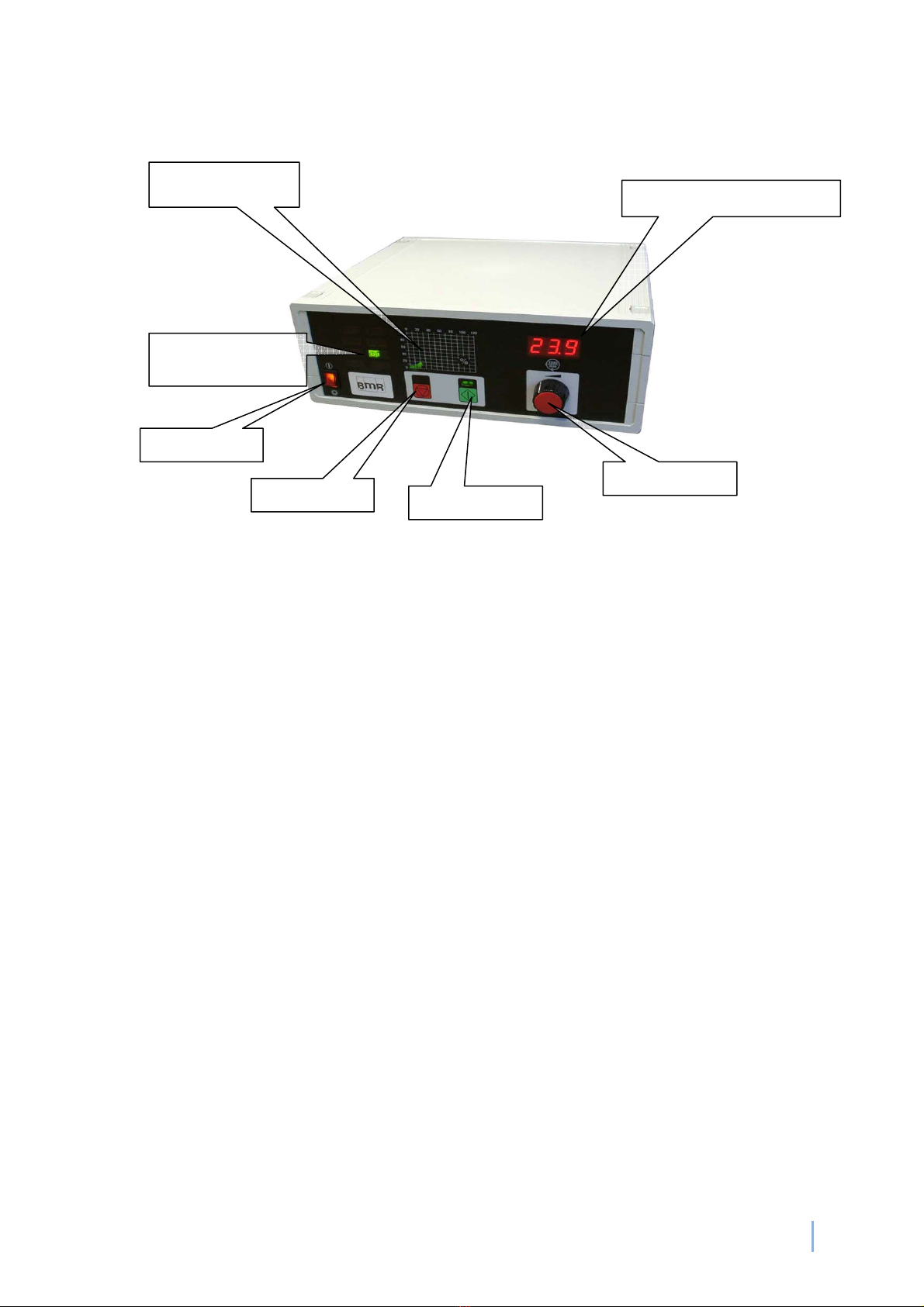
7.5 Cont ol via LED F ont Boa d
Mains Switch
After the Power-button is switched "ON", the Frequency Converter starts an automatically
self-test for about 8 seconds. During this time all displays flashes a short time one after
another. After this automatical check the converter is ready for operation.
In case of defect the corresponding display flashes.
Spindle "Sta t"
After pressing the „START“-button the spindle starts to come up to the rotational speed
adjusted by the rotary knob (11). The acceleration time is adjusted to 10.000 rps on factory
default.
On request other acceleration times are possible.
Spindle "Stop"
After pressing the "STOP"-button the spindle will be electronically decelerated and stopped to
standstill. The deceleration time corresponds to the adjusted acceleration time.
It’s only possible to slow down the spindle with the „STOP“-button if the remote control is not
„ON“.
By pressing power switch „OFF“ there is no electronic slow down, but the spindle runs out by
itself.
Digital Display of Rotational Speed
The digital display of rotational speed indicates the adjusted rotational speed by n x 1000
LED Load Display Display of Rotational Speed
RPM Poti
START Button
STOP Button
Mains Switch
LED Display for
Converter Status

14
SFU 0102/0202 F equency Conve te
7.6 LED-Displays
Display fo Conve te
Display fo Spindle
Load Display
The load display indicates the present load of spindle in %.
"green area" = within the admissibility
"red area" = overload
If the spindle is not loaded and no defect exists, the load-display indicates approx. „0%“.
Ove load Display
The display (2.3) always flashes, if the spindle was overloaded or the interruption for overload
responded.
Ove load Powe Cut
If the spindle is running more than 10 seconds [programmable by software (1 ... 10 sec.)] an interruption for
overload will follow.
I.e. after this time the converter automatically disconnects the spindle and the displays (2.2) and (2.3) are
flashing.
Another „power-up“ of the spindle can only follow if the display (2.2) disappears.
The display (2.3) disappears if the spindle is „powered-up“ again.
Display Pictu e
Desc iption
(2.1) converter superheat
(2.2) cconverter is not ready for
operation
(2.3) load of converter or load of
spindle higher than 100%
(2.4) remote control "ON"
Display Pictu e
Desc iption
(3.1) spindle superheat
(3.2) spindle is not ready for operation
(3.3)
rotational speed reaches "desired
value" or "actual vaue",
repectively
(3.4) standstill of spindle

…when it comes to quality! BMR GmbH
15
Excess Tempe atu e of Conve te
In case the converter reaches the excess temperature the display (2.1) flashes.
Delayed with 3 seconds [programmable by software (1...10 sec.)] the converter switches to „STOP“
and the display (2.2) flashes.
The spindle can not be switched „ON“ before the display (2.2) disappeared.
The display (2.1) disappears by another „power-up“.
Excess Tempe atu e of Spindle
In case the spindle reaches the excess temperature the display (3.1) flashes.
Delayed with 3 seconds [programmable by software (1...10 sec.)] the converter switches to „STOP“
and the display (3.2) flashes.
The spindle can not be switched „ON“ before the display (3.2) disappeared.
The display (3.1) disappears by another „power-up“.
Remote Cont ol
Optionally start behaviour through pin 11-12 connection at D-Sub 15
The remote control of the converter is connected via the 15-poles SUB-D-JACK (13).
The display (2.4) is on whenever the converter is remote controlled.
POSSIBILITIES OF REMOTE CONTROLLING:
a) Digitally: With a Start/Stop (0 / +24 ) signal at digital input1/ Pin12 .
The input can be setup to be Low- or Hi-active. The value of rotational speed can be preset with the
Potentiometer or with a DC-voltage at Pin11-8
b) Analogue: with a DC voltage at the analogue input. Connect (+) to Pin11 and (-) to Pin 8 (GND)
Precondition is a valid Start signal at Pin12
Uin < 0,5 is Spindle "Standstill" and Uin ≥ 0,5 is Spindle "ON".
Equally herewith the rotational speed is controlled
according to the scaling of speed to analogue value.
Possible is 1 /10.000rpM or 0-10 min/max.
c) RS232: with control commands via serial interface Pin13 (RxD), Pin14 (TxD) and Pin8 (GND)
A list of commands is available seperately on request.
ATTENTION:
The DC voltage at Pin11 must not excced 12 and should be free from ripple
voltages
ATTENTION:
This evaluation is only possible if the spindle is equipped with a
temperature sensor. (Option after arrangements)
If a Start is initiated by one of the above mentioned start operating modes, a subsequent
stop is accepted in the same mode only. This is valid not for safety functions
Tipp: It is ecommended to usw a shielded cable

16
SFU 0102/0202 F equency Conve te
Rotational Speed Reached
If the spindle reaches the preset value of the rotational speed, one of the two halves of
display (3.3) flashes.
The left half with the symbol „desired value“ flashes if the internal frequency of the converter
corresponds to the adjusted frequency.
This evaluation happens whenever the spindle is not equipped with a magneto resistor.
The right half of the symbol „actual value“ flashes if the spindle axle reached the adjusted
rotational-speed in fact (actual evaluation).
Standstill of Spindle
The display (3.4) flashes whenever the spindle axle stands still.
The converter considers two possibilities of the evaluation:
a) if the spindle is not equipped with a magneto resistor the symbol flashes when the converter
stopped giving more frequency (standstill of converter)
b) if the spindle is equipped with a magneto resistor the symbol flashes not before the spindle-
axle is standing still.
Configu ation1 ➔
➔➔
➔ ROTATIONAL SPEED OUTPUT
With the control connector (13) Pin 4 (+) and Pin 8 (
┴
) Ground, a direct voltage is given out
which corresponds to the rotational speed of the spindle axle. 1V / 10000 pm
Configu ation 2 ➔
➔➔
➔ ACTIVE LOAD OUTPUT
With the control connector (13) Pin 4 (+) and Pin 8 (
┴
) Ground, a direct voltage is
given out which corresponds to the load of the spindle. 0...10 V 0...100%
Reve sing Di ection of Spindle
To arrange the reversing direction of rotation, apply a direct-voltage of +12 ...24 on Pin 5
of the Control-Cennector (13).
[Pin 8 (⊥) Ground]
This function is only possible, if the spindle-axle stands still. [display (3.4) flashes].
If you arrange or disable the signal during the spindle rotates, the direction or rotation will
be changed after the next „standstill of spindle“.
INFORMATION: Standa d fo delive y is the configu ation " otational
speed output"!

…when it comes to quality! BMR GmbH
17
Eme gency Shutdown Inte lock
The emergency shutdown interlock can be programmed by software „active“ or „inactive“.
Programming „inactive“ is insignificant, whereas with a „active“ programming a primary stop-
command can be given. This means that the converter cannot be started again neither by
the „Start-button“ nor by the remote-control and that the spindle will be controlled slowed
down.
To abolish the command „shutdown-interlock“ there has to be applied a voltage of 5 ...30
on the control connector (13)
Pin 15 (+) and Pin 8 (⊥).
7.7 Setting up diffe ent Diag ams via F ont Boa d
To reach the menu first press the stop button and keep it down. Then press simultaneously
the start button and hold both for about 5sec. After this the actual nr, of the current spindle is
displayed. Now release the buttons. Now you can add one nr with the start button and take
one with the stop button. If a diagram is not valid an „E“ is displayed e.g. „E07“ in order to
show that diagram nr. 7 isn’t valid. A valid nr. is displayed as „07“ instead.
When approximately for 5 sec no button is pressed, the converter leaves the menu and is
doing a reset and the init routine like the switch-on procedure.
ATTENTION: The Spindle is not g ounded by the Conve te , but it has to be
g ounded via the spindle-suppo t

18
SFU 0102/0202 F equency Conve te
8. Calib ation and Configu ation with Windows-Softwa e
The software "SFU-Terminal " is an optional tool used to configure all frequency converters
0102...0601 and also provides the possibility of user-friendly data display and calibration,
implemented as follows:
1. Start-up frequency converter and connect via RS232 interface.
2. Start-up program SFUTerminal.exe
The interface is then configured automatically. A connected frequency converter is detected
and all data transfer parameters are synchronised.
This manual suits for next models
1
Table of contents
Other BMR Media Converter manuals


