BMR SFU 0303 User manual
…wenn es um Qualität geht! BMR GmbH 1

2SFU 0303 Frequenzumrichter
Issue November 2021 Rev. 2.1
6.1 Version SSE: Digital and Analogue Inputs X2 12
6.2 Version SSE: Digital and Analogue Outputs X3 13
6.3 Version SSE: Spindle Interface X4 14
6.4 Safe Torque Off –STO X5 16
6.5 Version SSE: Mains- and Spindle Connector 17
6.6 Version 19“ und Desktop: Digital and Analogue Inputs 18
6.7 Version 19“ und Desktop: Spindle Interface 19
6.8 Version 19“: Mains- and Spindle Connector 20
6.9 Version Desktop: Mains- and Spindle Connector 21
6.10 Version SSE: RS232, RS485 X1 23
6.11 Version 19“ and Desktop: RS232 23
6.12 USB-Connector 24
4.1 Version SSE 8
4.2 Version 19“ and Desktop 9
7.1 Front panel of SSE, Desktop und 19“ Version 25
7.2 Basics and Preconditions for Operation 26
7.2.1 Spindle Characteristics 26
7.2.2 Remote selection of Spindle Characteristics 26
7.2.3 Start and Stop 26
7.2.4 Safety Functions 27
7.2.5 Status Display 27
7.3 Status LED Display 28
7.4 LCD-Operating Panel 29
7.4.1 Operating Elements 29
7.4.2 Setup Menu 30
7.4.3 Error Messages 31
7.4.4 Settings 32
7.5 Start / Stop 33
7.6 Setup of Rotational Speed 34
7.7 Safety Functions 35
7.8 Safe Power Stage Pulse Lock 37
7.9 Safety Torque OFF - STO 38
1 Introduction 4
2 Description and Features 6
3 Block Diagram 7
4 TechnicalData 8
6 Connections, Interfaces and Pinout 11
7 7 Functions, Setup, Operation 22
5 Intended use / Safety Precautions and Warnings
10

…wenn es um Qualität geht! BMR GmbH 3
Stand November 2021
Stand November
2021
8 Profibus 41
9 Setup with Windows-Software 42
10 Automatic Spindle Tuning 43
12 EMV 47
13 Troubleshooting 48
11.1 Mains and Spindle Connection 45
11.2 Logic and Wiring for Safety 46
14 General Hints 52
15 Warranty 46
16 Accessories 47
17 Mechanics and Dimension 48
17.1 Version SSE for Cabinet Mounting 48
17.2 19“ Rack Mount Version 49
17.3 Desktop Version 50
11 Examples for Connection 45
18 Other products of BMR GmbH 51

4SFU 0303 Frequenzumrichter
1. Introduction
Due to its construction, the rotational speed of a 3-phase Asynchronous-AC-Motor is directly dependent
on the frequency of the voltage and the number of poles. In case of a 3PH 50Hz voltage and a 2-pole
motor, the nominal speed would be 50 rpsec * 60 = 3000 rpm.
In case of Synchronous-BLDC motors (brushless dc), the speed is directly dependent on the voltage
applied.
3-phase AC motors provide numerous benefits in industry, such as brushless operation, freedom from
wear and tear, favorable capacity/weight ratio, high-speed capability, and much more. These motors
can be used many different application areas, such as milling and grinding spindles, or with drilling
machinery, for example.
✓This unit is designed for operation in industrial environments only. When used in residential and
commercial areas, additional measures may be required to limit the emitted interference (→5. / 12.)
The advantages of SFU0303 compared to similar converters:
✓It is equipped with a Safe Power Stage Pulse Inhibition, authorized to current regulations EN 954_1
Categorie 3 corresponding to EN ISO 13849-1 Safe Torque Off One (ST01) = PLd / Cat 3
✓High output power ( 3,6kV @ 230V ) in compact case style
✓High efficiency by symmetrical PWM
✓Real time vector control for sensorless operation
✓Maximum Torque even at lowest rotational speeds
✓High possible acceleration rates for short process times. For example 25.000rpm/sec with a 2,2 KW
Motor (with robotic applications)
✓Pulse-Amplitude (PAM = Block-Modus) Control possible because of regulated intermediate voltage
control (on option)
✓Very low current consumption because of real time power control
✓Easy Integration into new and existing PLCs because of flexible I/O configuration
✓Various interface options: Profibus, RS485, RS232, USB
✓Easy reversing the direction of rotation by software without loss of power.
✓Autotuning function for spindle setup.
✓Testrun with graphical documentation of voltages and currents of the spindle
✓Up to 16 different spindle characteristics can be stored
✓Very user-friendly debugging interface for setup control
✓Start/Stop Interface for periodical tests or remote control

…wenn es um Qualität geht! BMR GmbH 5
✓Operating panel is detachable and can be used as remote control together with an extension cable.
✓Cloning capability of the whole project setup with the help of the Operating Panel
✓Designed for roughest use in industrial environment
✓Specific construction of the SSE-housing realized without ventilations slots and an outside mounted
heatsink prevents intrusion of dirt and chips of tooling into the control unit.
✓Very compact case style makes easy cabinet mounting possible
✓Several case options for cabinet mounting (SSE) , 19" rack style and desktop, or special designs on
request
✓User friendly Screw-plug connector system for power-, spindle- and I/O connectors.
✓Wide range of operating voltage 115V-230V
✓Automatic deceleration of the spindle down to standstill in case of mains failure by "Back Energy"
Function
✓Plain text messages and information on LC-display in amber color
✓Very user friendly operation menu.
✓USB connection and RS232 with specific adapter cable
✓Full functional without operation panel in remote configuration
✓Remote control hand-terminal available
✓Temperature controlled fan
✓Datalogger-Function on option available in combination with PC software SFU-Terminal. Records of all
relevant parameters of the converter in nearly infinite lengths are possible down onto the PC- hard disc.

6SFU 0303 Frequenzumrichter
2. Description and Features
✓Operation of Asynchronous-AC und Synchronous-BLDC Motors
✓The high frequency converter SFU-0303 makes possible output frequencies 500.000 rpm
with 2pole AC-Motors and with BLDC-Motors up to 100.000 rpm
✓High output power ( 3,6kV @ 230V / 2kVA @ 115V ) in compact style
✓The core of SFU-0303 is a Digital Signal Processor (DSP) which produces all output signals and collects
all input signals
✓All parameters like current, voltage and frequency are captured in real time and are regulated by the
implemented vector control depending on the load condition.
✓High precision sinusoidal output signals with low distortion factor realize very high accuracy in true
running behavior.
✓Allows highest efficiency of the spindles at low and high frequencies
✓High operational safety: All operating conditions like acceleration, operation with nominal rotational
speed, deceleration are monitored and critical conditions are intercepted.
✓STO Function for highest safety at standstill and protection against unintended starting
✓Integrated heavy duty brake-chopper-resistor for quick braking even from high speeds.
✓Transparency: The user is always informed about the current status of the converter and the spindle
on a plain text 3-line operating panel.
✓Control: If needed, the converter can be controlled and parameterized manually with a pluggable
operating panel.
✓Easy reversing the direction of rotation by Software without loss of power.
✓Individual adjustment to the current application and the connected spindle. Up to 16 different
characteristics can be stored in the converter
✓A variety of options for control and communication possibilities: For communication with peripheral
devices, such as PC, PLC or CNC, there are 3 ports available:
✓Easy and flexible integration into existing equipments by free configuration of I/Os
Control inputs: 2 Analog, 6 Digital
Control Outputs: 2 Analog, 6 Digital (Relay)
✓Galvanic separation of all interfaces from each other and from mains / spindle potential
✓Short circuit proof
✓Comfortable Configuration und control with the help of a PC-Windows software "SFU-Terminal"
✓Cloning-Function with operating panel: Creating of clones of converters by individual read out of the
SFU-parameters into the operation panel and download into another or multiple SFUs.
✓Automatic spindle calibration by autotuning function
…wenn es um Qualität geht! BMR GmbH 7
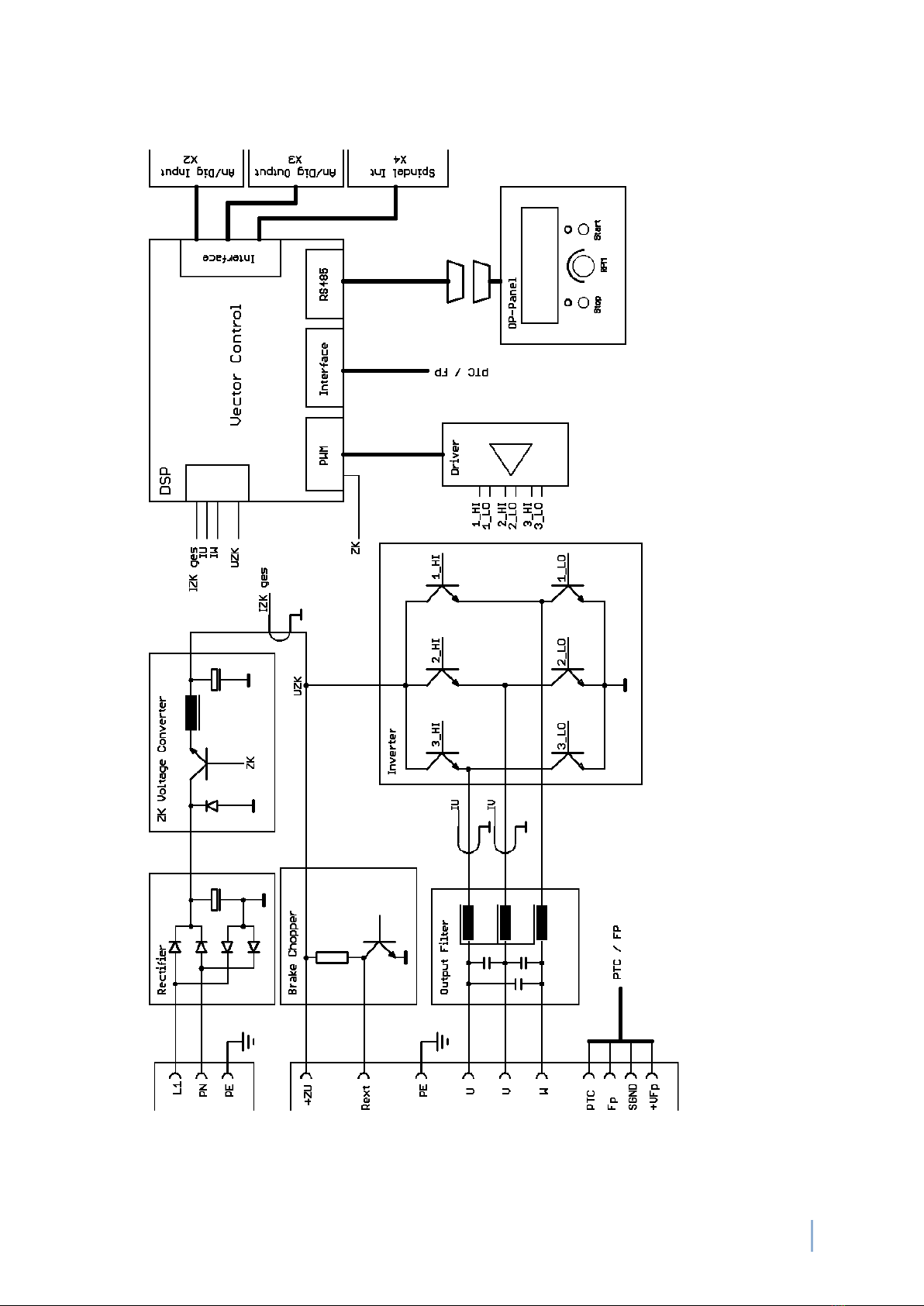
3. Block Diagram

8SFU 0303 Frequenzumrichter
4. Technische Daten
4.1 Version SSE
ATTENTION
The operation of a spindle with a wrong characteristic may harm the spindle or
converter severely! Please ensure to have the proper characteristic selected always!
Mains connection 115V, 60Hz 230V, 50Hz
3-pin: plugable screw terminals 4mm²
Continuous output power
2 kVA / S1-100% 3,6 kVA / S1-100%
Motor connection
Output voltage
110V 220V
Output current
Output current overload
Output frequency
Spindle characteristics
Spindle sensor inputs
Control inputs
2 Analog: 0-10V
6 Digital: 0-24V
2 STO: 0-24V
Control outputs
Interface
Dimensions
Weight
Protection
Operating conditions
5 - 40°C / rel. humidity max. 85%
IP20
- USB on operating panel (USB-Mini)
- RS232, RS485 on SFU (9 pol DSub male)
- Profibus on Option as module, replacing operating panel
10-pin: plugable screw terminals 4mm²
PE, U, V, W, Temperature sensor, FP, SGND
elektronically limited, max. 13A
2 Analog: 0-10V
5 x Digital, freely to be setup
1 x Digital reserved for power stage impuls inhibitor or STO
Relay contacts, 24VDC/1000mA, 125VAC/500mA
12 pin plugable screw terminals X3
see chap 17
approx. 6 kg depending on version
Speed sensor, PTC, KTY, PT1000
maximum duration adjustable 0…20sec
AC: max 8,8kHz / 500.000 rpm
DC: max 1.667Hz / 100.000 rpm
max. 16, stored internally

…wenn es um Qualität geht! BMR GmbH 9
4.2 Version 19" und Desktop
ATTENTION
The operation of a spindle with a wrong characteristic may harm the spindle or
converter severely! Please ensure to have the proper characteristic selected always!
Mains connection 115V, 60Hz 230V, 50Hz
3-pin: plugable screw terminals 4mm²
Continuous output power
2 kVA / S1-100% 3,6 kVA / S1-100%
Motor connection
Output voltage
110V 220V
Output current
Output current overload
Output frequency
Spindle characteristics
Spindle sensor inputs
Control inputs
2 Analog: 0-10V
6 Digital: 0-24V
2 STO: 0-24V
Control outputs
Interface
Dimensions
Weight
Protection
Operating conditions
5 - 40°C / rel. humidity max. 85%
IP20
- USB on operating panel (USB-Mini)
- RS232, RS485 on SFU (9 pol DSub male)
- Profibus on Option as module, replacing operating panel
9-pin: plugable screw terminals 4mm²
U, V, W, Temperature sensor, FP, SGND, 2x PE or
Circular connector 7 or 13 Pin
U,V,W,FP,SGND,Shield, PE
elektronically limited, max. 13A
2 Analog: 0-10V
5 x Digital, freely to be setup
1 x Digital reserved for power stage impuls inhibitor or STO
Relay contacts, 24VDC/1000mA, 125VAC/500mA
12 pin plugable screw terminals X3
see chap 17
approx. 6 kg depending on version
Speed sensor, PTC, KTY, PT1000
maximum duration adjustable 0…20sec
AC: max 8,8kHz / 500.000 rpm
DC: max 1.667Hz / 100.000 rpm
max. 16, stored internally

10 SFU 0303 Frequenzumrichter
5Intended Use / Safety Instructions and Warnings
✓This device produces dangerous electrical voltages and is used for the operation of fast spinning tools.
Because of their high rotational speed, it may be dangerous in case of improper handling. For this
reason, only professionally trained and qualified personnel should be allowed to work with and setup
this device!
✓Before the first commissioning can be carried out, it should be ensured that the spindle and the tool
are fixed properly, to eliminate all dangers because of uncontrolled movement of the spindle.
✓Safety regulations being valid for the country where the device is used, have to be adhered to where
any work is carried out on the device.
✓Before the device is turned on for the first time, it should be verified, that the connected parts cannot
carry out uncontrolled movements.
✓The frequency converter must not be operated close to heating devices or magnets or devices
generating strong magnetic fields.
✓Sufficient air circulation around the converter should be ensured.
✓Fluids should be prevented from intruding into the housing. If it seems to be happened, the converter
has to be switched off immediately.
✓The ambient air must not use aggressive, flammable or electrically conductive substances and should
be as free of dust as possible.
✓All repairs and maintenance on the converter and the relating accessories must be carried out by
skilled personal and with powered off, only. To ensure this, the mains plug should be pulled out. In
doing this, both the terms of regulations for preventing accidents and the general and national rules
for mounting and safety have to be applied.
✓Do not open this device while it is connected to power supply. There is danger of life!
With opening this unit the period of warranty will be ended.
✓All people who work with this device should be trained and instructed by their line advanced
technician.
Please ensure, that PE protective earth is connected at the mains side. The device
must not be operated without properly connected PE!
Version SSE has no internal fusing. It has to be fused externally
Please ensure, that PE protective earth is connected at the spindle side as well as at
the converter side!

…wenn es um Qualität geht! BMR GmbH 11
6Connections, Interfaces and Pinouts
For embedding into PLC and controls the SFU0303 has several input and outputs.
They are realized as pluggable screw terminals and are located at the front or rear panel (depending
on case option). All contacts are separated galvanically from high voltage carrying circuits.
Operational parameters and outputs:
The SFU-0303 captures all current important operational parameters and operating data.
Up to 6 digital outputs can be used for signaling and up to 2 analogue values can be output to the
analogue outputs (0-10V).
Remote Control and Outputs:
6 digital inputs (24V) and 2 analogue inputs (0-10V) are available for remote control of the
SFU-0303.
These assignments can be configured freely. By using the optional Windows PC software "SFU-
Terminal" the above mentioned assignments can be achieved easily, providing exceptional flexibility
with each application.
Each operating parameter can be assigned as a signal and each control signal can be assigned to a
certain I/O pin. In addition, the logic level (high or low active) can be individually defined.
The same assignment is also possible for the analogue measured data and control data at the analogue
I/O pin.
The standard allocations of operational parameters, their outputs, control signals and inputs, are listed
in the following tables.
ATTENTION
Please verify that all power supply voltages are correct in polarity and value.
ATTENTION
Please ensure to have the proper characteristic selected, always!
The operation of a spindle with a wrong characteristic may harm the spindle severely!
ATTENTION
In case of replacing the fuses, please ensure to use types only, which are
mentioned in 'Technical Data'!

12 SFU 0303 Frequenzumrichter
6.1 Digital and Analog Inputs Version SSE: X2 (10 pin pluggable screw terminal)
The Default-settings of the functions for the outputs can be set up freely with the help of the PC-
Software SFU-Terminal.
✓Switching level digital inputs: Log"0" = 0…7V / Log"1" = 18….24V SPS Standard level
✓Analogue input range: 0…10V
✓The +24V at Pin 10 can be used as auxiliary voltage supply for Start / Stop signal with the help of a
relay or for an electronic spindle interface.
Pin Description Description Function / default Setting Switching state
1
Digital In 1 Input Start / Stop "0" Stop / "1" Start
2 Digital In 2 Input
Power Stage Pulse Lock Inhibitor /
no function with Version STO
"0" activated / "1" released
3
Digital In 3 Input Power Stage Off "0" Aus / "1" On
4 Digital In 4
Input Locked / Emergency Stop "0" released / "1" Emergency Stop
5
Digital In 5 Input Error reset
"0" Errors have to be reset,
with Hi level on this Input or
with any Start signal
"1" Errors are rest automatically
6 Digital In 6 Input Direction of rotation "0" unchanged / "1" inverted
7
Analog In 1 Input
Set value Rotational speed
Scaling 10V min/max
rot. speed converter
1V/10.000
8 Analog In 2
Input Set value Varioload
active load
1V/10.000
9 GND
Reference Ground for die Digital and
Analog signals
10
+ 24V/50ma
Output Auxiliary voltage supply
…wenn es um Qualität geht! BMR GmbH 13
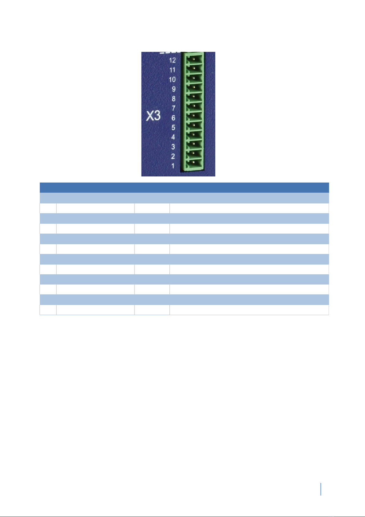
6.2 Digital and Analog Outputs Version SSE: X3 (12 pin Pluggable screw terminal )
The Reference-Ground for digital and analog signals: Clamp terminal X2.9
The Default-settings of the functions for the outputs can be set up freely with the help of the PC-
Software SFU-Terminal.
An exception is the signal "Power Stage Pulse Lock", which is linked fix with Relay 6. According to
the switch state it will be output 0V / GND or +24V via 10kΩreferring to GND (X2.9) (-> 8.2 / 8.7)
+24V: Output Power Stage released 0V: Output Power Stage locked.
✓Relay Output:
1) default = "not energized" corresponds to "not active"
inactive condition at opener (NC contact) →Contact closed
inactive condition at closer (NO contact) →Contact opened
Pin Description Direction Function / Message / default Setting
1
Relay Common Common Rail Relay 1…5
2 Relay 6 normally closed Output Feedback signal for Power Stage Pulse Lock state
3
Relay 5normally closed Output Excess temperature Converter of Spindle
4 Relay 4normally closed
Output Overload
5
Relay 3normally closed Output Standstill Converter and Spindle
6 Relay 2normally closed Output Spindle Ready
7
Relay 2normally open Output
8 Relay 1normally closed
Output Converter Ready
9 Relay 1normally open Output
10 Analog Out 1 Output
11 Analog Out 2 Output
12 Hall Sensor-Output Output modified signal square shape signal from encoder

14 SFU 0303 Frequenzumrichter
2) With SFU-Terminal the "active" function of the relays can be changed to "not energized " also. By
this an inversion is achieved, with the restriction that this is applied to the inverter during operation at
POWER-ON, only, because it is just realized by software. At POWER-OFF, the relay contacts have the
default setting as in 1 )
✓The digital outputs (Relay1...5) are galvanically separated (500VIsolation).
DC: 24V / 1000mA AC: 125V / 500mA
✓Output level Speed / Hall Sensor: 0-24V (24V Level)
6.3 Spindle Interface - Version SSE: X4 (9 pin Pluggable screw terminal)
The Default-settings of the functions for the inputs can be set up freely with the help of the PC-
Software SFU-Terminal. The inputs of the encoder and the PTC are fix wired.
Pin Description Direction Function
1
+12V/50mA Output Auxiliary voltage supply
2 Spindle GND Reference Ground for Speed- and Temp-sensor
3
NC not connected
4 FP/Speed sensor Input
Input for 2/3-wire speed sensors /
Hall sensors from spindle
5
Temperature
Sensor Input Temperature signal from spindle: PTC, KTY, PT1000
6 Bit 4 Input Characteristic selection by digital inputs
7
Bit 3 Input Characteristic selection by digital inputs
8 Bit 2
Input Characteristic selection by digital inputs
9 Bit 1 Input
Characteristic selection by digital inputs

…wenn es um Qualität geht! BMR GmbH 15
✓The spindle interface is separated with optocouplers from all other signals. It can be used for an
automatic spindle detection, if activated. The logic levels are low-active by default:
✓"HI" > PIN connected with Spindle-GND, "LO"- > PIN unwired
In the menu "Digital Inputs" this can be changed.
✓GND signal X4 is electrically isolated from GND X2
✓The temperature sensor input is provided to detect overtemperature on the spindle. With linear
temperature sensors (KTY, PT1000), the switching thresholds for the error messages "Spindle
overtemperature" can be freely defined using the SFU terminal. If PTC is selected, it will be triggered as
soon as the PTC resistance is > 600Ω. In both cases, it is switched off after the delay time has expired
✓The input 4 for the speed sensor works in the range of +/- 1V with a common mode range of 0..10V.
✓The +12V at Pin 1 can be used as auxiliary voltage supply
✓Spindle characteristic remote controller / Characteristic selection by digital inputs
✓In SFU - Terminal main menu the spindle characteristics remote control can be enabled . In this case,
the manual selection is inactive
The addressing is binary coded: KL-Nr. "Value+1"
Bit 4 Bit 3 Bit 2 Bit 1 Spindle characteristic
0 0 0 0 1
0 0 0 1 2
0 0 1 0 3
………
1 1 1 1 16
ex.: all Pins open 0000 = 0 + 1 →Characteristic 1
0101 = 5 + 1 →Characteristic 6
The number of the selected spindle characteristic is displayed on the display at the right top.

16 SFU 0303 Frequenzumrichter
6.4 Safe Torque Off –STO: X5 (6 pin Pluggable screw terminal)
✓STO Channels 1 and 2 and the feedback Contactare isolated galvanically from each other and to all
other I/Os.
✓The STO-Inputs tolerate voltage levels of ±60-V and are reverse protected, with the and have reverse
polarity protection that meets the characteristics of IEC 61131-2 types 1, 2 and 3.
Level STO-A/B
0…5V = low
5,1V…..14,9V
15…30V (max.
60V) =high
State STO
STO active
not defined
STO inactive
Converter is locked
not defined
Converter is ready
Relay contact
open
not defined
closed
✓The relay contact between Pin1 and 2 is potential-free and serves as feedback signal about the STO
channels
Attention:
The feedback contact is realized as single channel only. So it may only be used for monitoring purpose
and must not be used within safety circuits.
✓The feedback contact is open in case of STO is active →converter is locked
-With no signal or 0V at the control inputs STO-A and STO-B
-With no signal or 0V at one of the control inputs. →STO-Error
-If the power supply for the logic is missing
✓The feedback contact is closed in case of STO is inactive →converter is unlocked
Details →7.9
Pin Name Direction Function
1
Contact 1
2
Contact 2
3
GND STO-B GND for STO-B , Chanal 2
4 STO-B Input Input STO-B Pulse Blocking Channel 2
5
GND STO -A GND für STO-A , Kanal 1
6 STO-A Input Input STO-B Pulse Blocking Channel 1
STO Status
STO Status Feedback Relay /
normally open contact
…wenn es um Qualität geht! BMR GmbH 17
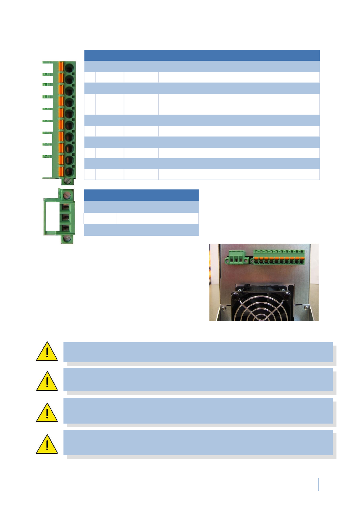
6.5 Mains and Spindle connection at SSE
View at screw terminals at version SSE:
Please ensure, that PE protective earth is connected at the mains side. The device
must not be operated without properly connected PE!
Version SSE has no internal fusing. It has to be fused externally
Please ensure, that PE protective earth is connected at the spindle side as well as at
the converter side!
Control wires, Mains cables and spindle cables should be installed separately.
For wiring, the use of shielded cables is recommended.
+VFP
SGND
FP
Temp. Sens.
W
V
U
Rext
+ZU
PE
PE
N
L
Pin Name Direction Function
1
+VFP Output Auxiliary voltage supply 12V/50mA
2 SGND Ground reference for FP, temperature sensor
3
FP Input Input for 2/3-wire speed sensors / Hall sensor
4
Temp-
sensor
Input Temperature signal from spindle: PTC, KTY, PT1000
5
W Output Spindle Phase W
6 V Output Spindle Phase V X4
7
U Output Spindle Phase U
8 Rext
Output External Brake resistor / Chooper Resistor
9 +ZU Output
Intermediate voltage (! Attention, High Tension!)
10 PE Output
Connection for protective earth of spindle ! Safety !
Name Function
PE
Protective Earth ! Safety !
N Neutral
L
Line Phase

18 SFU 0303 Frequenzumrichter
6.6 I/O Interface - Digital and Analog In- and Outputs
19"Version and Desktop: (D-Sub 25pin female)
The Default-settings of the functions for the outputs can be set up freely with the help of the PC-
Software SFU-Terminal.
An exception is the signal "Power Stage Pulse Lock", which is linked fix with Relay 6. According to the
switch state it will be output 0V / GND or +24V via 10kΩreferring to GND (7, 19) (-> 8.2 / 8.7)
+24V: Power Stage released 0V: Power Stage locked.
✓The digital outputs (Relay1...5) are galvanically separated (500VIsolation).
DC: 24V / 1000mA AC: 125V / 500mA
✓Switch level digital inputs: 0..7V = "0" / 18..24V = "1"
✓Analogue input range 0…10V
✓Output level Speed / Hall Sensor: 0-24V (24V Level)
✓+24V at Pin6, 18 may be used as auxiliary power supply for e.g. an electronic spindle interface
Pin Description Direction Function / Massage / default Setting
1,14
Relay Common Common Rail for Relay contacts
2
Relay 1 Normally Closed Output
15
Relay 2 Normally Closed Output
3
Relay 3 Normally Closed Output
16
Relay 4 Normally Closed Output
4
Relay 5 Normally Closed Output
17
Relay 6 Normally Closed Output Feedback signal for Power Stage Pulse Lock state no function with STO
5 Relay 1Normally Open Output
6,18
+24V/50mA Output Auxiliary voltage for active field plates
7,19 GND
20
Relay 2 Normally Open Output
8 Hall Sensor Output Modified signal from speed sensor
21
Digital In 2 Input Power Stage Pulse Lock
9 Digital In 6 Input
22
Digital In 5 Input
10 Digital In 4 Input
23
Digital In 3 Input
11 Digital In 1 Input
24
Analog In 1 Input
12 Analog In 2 Input
25
Analog Out 1 Input
13 Analog Out 2 Input

…wenn es um Qualität geht! BMR GmbH 19
6.7 Spindle Interface - 19"Version and Desktop: (D-Sub 15pin female)
The Default-settings of the functions for the outputs can be set up freely with the help of the PC-
Software SFU-Terminal. The inputs of the encoder and the temperature sensor are fix wired.
✓The spindle interface is separated with optocouplers from all other signals. It can be used for an
automatic spindle detection, if activated. The logic levels are low-active by default: "HI" > PIN
connected with Spindle-GND, "LO" > PIN open. In the menu "Digital Inputs" this can be changed.
✓The temperature sensor input is intended for detecting overtemperature at the spindle. With linear
temperature sensors (KTY, PT1000), the switching thresholds for the error messages "Spindle
overtemperature" can be freely defined using SFU-Terminal. If PTC is selected, this is triggered as soon
as the PTC resistance is > 600 Ω. In both cases, it is switched off after the delay time has elapsed
✓The input 4 for the speed sensor is working within the range of +/- 1V with a common mode range of
0..10V.
✓The +12V at Pin 1 can be used as auxiliary voltage supply.
(→see 6.3)
Pin Name Direction Function
1
nc not connected
9 +12V/50mA Output Auxiliary voltage supply
2,1
SGND Ground reference for FP, temperature sensor
3,11
Bit 0 Input Characteristic selection by digital inputs
4,12
Bit 1 Input Characteristic selection by digital inputs
5,13
Bit 2 Input Characteristic selection by digital inputs
6,14
Bit 3 Input Characteristic selection by digital inputs
7,15
Temp-
sensor
Input
Temperature signal from spindle: PTC, KTY, PT1000
8
Hall Sensor Input Speedsensor signal from spindle

20 SFU 0303 Frequenzumrichter
6.8 Mains and Spindle connection - 19" Version:
Back side SFU0303-19" with spindle connector clamp terminal
Spindle Connector - 9pin clamp terminal
Mains connection - 3pin clamp terminal
Please ensure, that PE protective earth is connected at the mains side, always. The
device must not be operated without properly connected PE!
Please ensure, that PE protective earth is connected at the spindle side as well as at
the mains side, always.
Control wires, Mains cables and spindle cables should be installed separately.
For wiring, the use of shielded cables is recommended.
Spindle Connector
Mains
Connection
Automatic Thermal Fuse
Spindle
interface
Interface
I/O
interfaceI
nterface
Pin Name Direction Function
1
+VFP Output Auxiliary voltage supply 12V/50mA
2 SGND Ground for signals FP, PTC
3
FP Input Input for two/three wire-speed sensors
4
Temp-sensor Input
Temperature signal from spindle: PTC, KTY, PT1000
5
W Output Spindle Phase W
6 V Output Spindle Phase V
7
U Output Spindle Phase U
PE PE
PE PE
Connection for protective earth of the spindle ! Safety !
Name Function
PE
protective earth ! Safety !
N
Neutral
L Phase
Table of contents
Other BMR Media Converter manuals


Popular Media Converter manuals by other brands

Allanson
Allanson ACL-SC3C4A-DMX quick start guide

Marshall Electronics
Marshall Electronics BC-0909-DA user guide

Intrepid Control Systems
Intrepid Control Systems RAD-Galaxy user guide

Altinex
Altinex SR208-100 user guide

WaveSplitter
WaveSplitter WST-PSP003 Operation manual

Gefen
Gefen HDSDI-2-DVIL user manual


TRU Components
TRU Components 2207472 operating instructions

MSB Technology
MSB Technology Universal Media Transport plus user manual

Sumake
Sumake ST-2556 quick start guide

gofanco
gofanco PRO-HD2SDI user guide

Mitsubishi Electric
Mitsubishi Electric MELSERVO-J4 series Specification manual

Audioroot
Audioroot eSMART BG-DU quick start guide