BMR SFU 0156 User manual

Frequency Converter SFU 0156

SFU 0156 M a n u a l
E 2015-10-15
2
Content
1 Description and Features
2 Technical Data
3 Safety and Caution Instructions
4 Connections, Plugs and Pin Assignments
4.1 Power Supply Connection SL4
4.2 Spindle Connection SL3
4.3 Inputs and Outputs SL2
4.4 USB Interface
4.5 Serial Interface SL5
4.6 Adapter Cable
5 Description of Functions and Operation
5.1 Start and Stop
5.2 Set Value of Rotational Speed
5.3 Outputs
5.4 LEDs
6 Example for I/O Wiring
7 Safety Functions
8 EMC
9 Power Supply Set (as option)
10 Remote Control
11 Drawing and Mounting
We thank you for choosing a BMR-Product !
This product was carefully developed and manufactured in Germany
at BMR-GmbH
>Please read this manual carefully before first operation!

SFU 0156 M a n u a l
E 2015-10-15
3
1. Description and Features
•Operation of AC spindles and BLDC spindles
•The frequency converter SFU 0156 allows speed frequencies up to 100.000Upm with 2-
pole spindles.
•The core of SFU-0156 is a digital signal processor (DSP) which produces all output
parameters and collects signals.
•High-precision sinusoidal output signals with a low distortion factor and low
deformation allow for optimal rotation qualities in AC motors of all operating conditions
•All parameters like power, voltage and frequency are collected in real time and are
regulated by the implemented vector control depending on the load.
•High operating safety: All operating conditions like acceleration, operation with nominal
rotation speed, braking are controlled and critical conditions are intercepted.
•Short circuit protected
•on board chopper resistor
•Protection against excess temperature.
2. Technical Data
Power Supply SL4 Logic Supply: 24V / 0,25A DC (max. 30V)
Spindle Supply: max. 80V / 6A DC pluggable screw terminals 4mm2
Fuses FS1:T250mA recommended Littelfuse 0477.500XP
FS2:T6,3A recomm. Littelfuse 0477 06.3XP / SIBA 179200 6.3
Power 400VA
Spindle Connection SL3 4-pin: U, V, W, PE pluggable screw terminals 4mm2
Output Voltage depending on the spindle characteristic: max. 3 x 60V
Output Current electronically limited and matched to the corresponding spindle
Output Frequency AC: 1.667Hz / max 100.000 rpm
Control Inputs SL2 Pin1 / DI - digital in: Start / Stop ( 0 / 24V ) "0": 0..7V, "1": 18..24V
Pin3 / AI - analogue in: Set Value Rotational Speed ( 0..10V )
Control Outputs SL2 Pin9 / DO1 - digital out: free configuration: open collector 45V/0,5A
Pin7 / DO2 - digital out: free configuration: open collector 45V/0,5A
Pin10 / DO3 – digital out: free configuration: open collector 45V/0,5A
PIN6 / AO - analogue out: Output Load ( 0..10V )
Operating Status
Indicators Converter Ready: LED green Converter Overload: LED red
Interface SL5 - RS232: 115.200Bd, 8Data 1Stop Bit, No Parity
- USB Interface (USB-Mini)
Dimensions Approx..132 x 111 x 43 L x B x H (mm) open frame style
Chopper Resistor 47Ohms / 10W
Operating Conditions 10°C bis 40°C / Rel. Humidity max. 80%
- Maximum Surrounding Temperature: 40°C.
- The inverter shall be installed in a pollution degree 2 environment.
SFU 0156 M a n u a l
E 2015-10-15
4
3. Safety-Precautions and Warnings
•This device produces dangerous electrical voltages and is used for the operation of fast
spinning tools. Because of their high rotational speed, it may be dangerous in case of
improper handling. For this reason, only professionally trained and qualified personnel
should be allowed to work with and setup this device!
•Any maintenance to the device must be carried out after the supply voltage has been
disconnected, only!
•Before the first commissioning can be carried out, it should be ensured that the spindle
and the tool are fixed properly, to eliminate all dangers because of uncontrolled
movement of the spindle.
•Safety regulations being valid for the country where the device is used, have to be
adhered to where any work is carried out on the device.
•Maintaining EMC (electromagnetic compatibility) limits is the responsibility of the
manufacturer of the machine or device. The inputs and outputs on this device are fitted
with filters, to increase the interference immunity and reduce emitted interference,
making it possible to use this device in an industrial environment.
•The EMC of a machine or device is affected by all connected components (motor
spindle, length and type of cables, wiring, etc). Under certain conditions the use of
additional filters can be necessary to maintain the current laws.
•For the reasons listed above, installation and connection of the device should be carried
out by qualified personnel, only.
Attention:
Please verify that all power supply voltages are correct in polarity and value
Attention:
Please ensure to have the proper characteristic selected, always!
The operation of a spindle with a wrong characteristic may harm the spindle
severely!
Attention:
In case of replacing the fuses, please ensure to use types only, which are
mentioned in 'Technical Data'!
SFU 0156 M a n u a l
E 2015-10-15
5
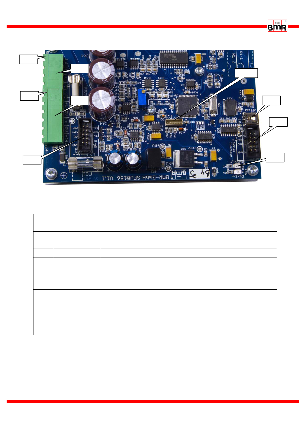
4. Connections, Plugs and Pin Assignments
* X-ICD for internal use only
4.1 Power Supply Connection SL4 (pluggable screw terminals)
Pin Function Description
1 PE Protective Earth, is internally connected to mounting bracket
2 +80VDC + Supply Voltage for spindle -> Fuse FS2 6,3AT
ÎAttention, not protected against voltage reversal
3 0V (80V) Voltage Return for spindle supply
4 PTC / KTY Temp sensor Spindle
Îavailable at HW V1.1 and to be configured with SFU-Terminal
> V6.25
5 0V (24V) return for controller supply (internally connected with PIN3)
6 +24V (max 30V)
+ Supply voltage for control logic -> Fuse FS1 250mAT
protected against voltage reversal with Diode D8
NC Version SFU0156 with onboard +24V logic supply
In this version the logic supply voltage is directly generated from the
spindle supply voltage (Æ9. )
SL3
SL4
SL2 LEDs
X-ICD*
PIN1
PIN1
SL5
USB
SFU 0156 M a n u a l
E 2015-10-15
6
4.2 Spindle Connection SL3 (pluggable screw terminals)
4.3 Inputs and Outputs – I/O Interface SL2 (2.54mm Header)
Pin Function Description / default function
1 DI Digital Input Start/Stop
3 AI Analog Input Set value for rotational speed
2,4 Ground Ground Ref for Pin 1,3,5,7,8,9,10 (internally connected with SL4.3/5)
5 +5V /10mA
max auxiliary supply(1)
6 AO Analog Out Output 0…10V ( free configuration)
default setting: Load Percent
7 DO2
Open Collector 2 Output (for free configuration)
default setting: Overload
8 +24V /10mA
max auxiliary supply(1) (internally connected with SL4.6)
9 DO1
Open Collector 1 Output (for free configuration)
default setting: Converter Ready
10 DO3
Open Collector 3 Output (for free configuration)
default setting: Duty Speed Reached
The scaling of the analog input can be modified, as well as the function of the open collector
outputs can be defined freely. The noted functions are the factory default setup.
On option a remote controller is available which can be connected directly with the
I/O interface at SL2. (Æ10.
4.4 USB Interface (alternative with RS232 Æ4.6)
The SFU 0156 has an USB Mini connector for easy access to "SFU-Terminal" configuration
program. You have the options to setup and configure the converter. The USB interface is
using the same interface channel as the RS232 interface (4.5) so that either one of both can
be used, only.
Pin Function Description
1 W Spindle Phase W
2 V Spindle Phase V
3 U Spindle Phase U
4 PE Protective Earth of spindle and cable shield

SFU 0156 M a n u a l
E 2015-10-15
7
4.5 Serial Interface RS232 SL5 (2.54mm Header) (alternative with USB Æ4.5)
Pin Function
1,2,4,6,7,8 NC
3 RxD
5 TxD
9 GND
10 NC
4.6 Adapter Cable for SL2 and SL5
For easy connection to SL2 and SL5 a standard(2) ribbon cable connector with Dsub9 fem is available
as option.
(1) Attention, with using and wiring these auxiliary voltages particular care is required and lies under the
responsibility of the user! These voltages may be used as auxiliary voltage but are not especially
fused. +24V is directly connected to FS1 and +5Vdig is directly connected with the DSP and all other
ICs. So, potential errors at the wiring may harm the board severely!
(2) Attention, On request a non standard cable is available with a special wiring which makes OC3
accessible at PIN7 of the 9Pin D-Sub
DSub-Pin SL2-Pin Funktion an SL2
1 1 Digital Input1
2 3 Analog Input1
3 5
+5Vdig (1)
4 7 Open Collector 2
5 9 Open Collector 1
6 2 GND
7 10 GND
8 6
Analogue Out
9 8
+24V (1)
7 10(2) Open Collector 3
DSub-Pin SL5-Pin Funktion an SL5
1 1
2 3 RxD
3 5 TxD
4 7
5 9 GND
6 2
7 4
8 6
9 8

SFU 0156 M a n u a l
E 2015-10-15
8
5. Functions, Setup, Operation
5.1 Start / Stop
There are two possibilities to start the spindle:
digitally with a digital control signal at digital input1 Start/Stop at SL2.1.
The switching levels for "OFF=0" are 0...7V and for "ON=1" 18...24V,
voltages between 7V and 18V are undefined.
ÎAs soon as this is initiated, the spindle will be accelerated to the set value of the
rotational speed which is pre-selected as voltage at analogue input1 Set Value of
Rotational Speed at SL2.2.
analogue with a voltage at analogue input1
Precondition is a valid "ON" signal at digital input1 Start/Stop
ÎAn input voltage of 0V makes the spindle stop, and a voltage higher than 0,29V
starts the spindle up to a rotational speed according to the scaling.
5.2 Set Value of Rotational Speed
There are two possibilities for scaling the rotational speed
•0-10V / Min-Max: The default scaling for the analogue value is according the
Min/Max values of the rotational speed from the spindle characteristic
e.g.: set values are Min: 5.000rpm, Max: 60.000
This results in a formula for the control voltage u: u = set value * 10V/60.000rpm
A voltage of u<0,8V realizes standstill, a voltage of 0,8V sets the minimum speed of
5.000rpm and 10V sets the maximum rotational speed of 60.000rpm.
•Another option of the input scaling is 1V/10.000rpm.
5.3 Outputs
Digital Outputs:
As feedback signals to a PLC or another control there are 3 open collector outputs
available. They indicate the current operational status of the converter. (Æ6.)
The functions can be setup freely, factory default is listed below
DO1 / SL2.9 default Converter Ready . In this case, the PIN is drawn to ground
DO2 / SL2.7 default Overload. In this case, the PIN is drawn to ground
DO3 / SL2.10 default Duty speed reached. In this case, the PIN is drawn to ground
Analogue Output:
As a default function the output load condition is output as a voltage between 0..10V at
the analogue output AO / SL2.6. with a scaling of 1V/10% . Other function values are
available and can be setup with SFU-Terminal.
Analogue input circuit
SFU 0156 M a n u a l
E 2015-10-15
9
5.4 LEDs
Likewise the open collector outputs, there are LEDs indicating the current operational
status of the converter.
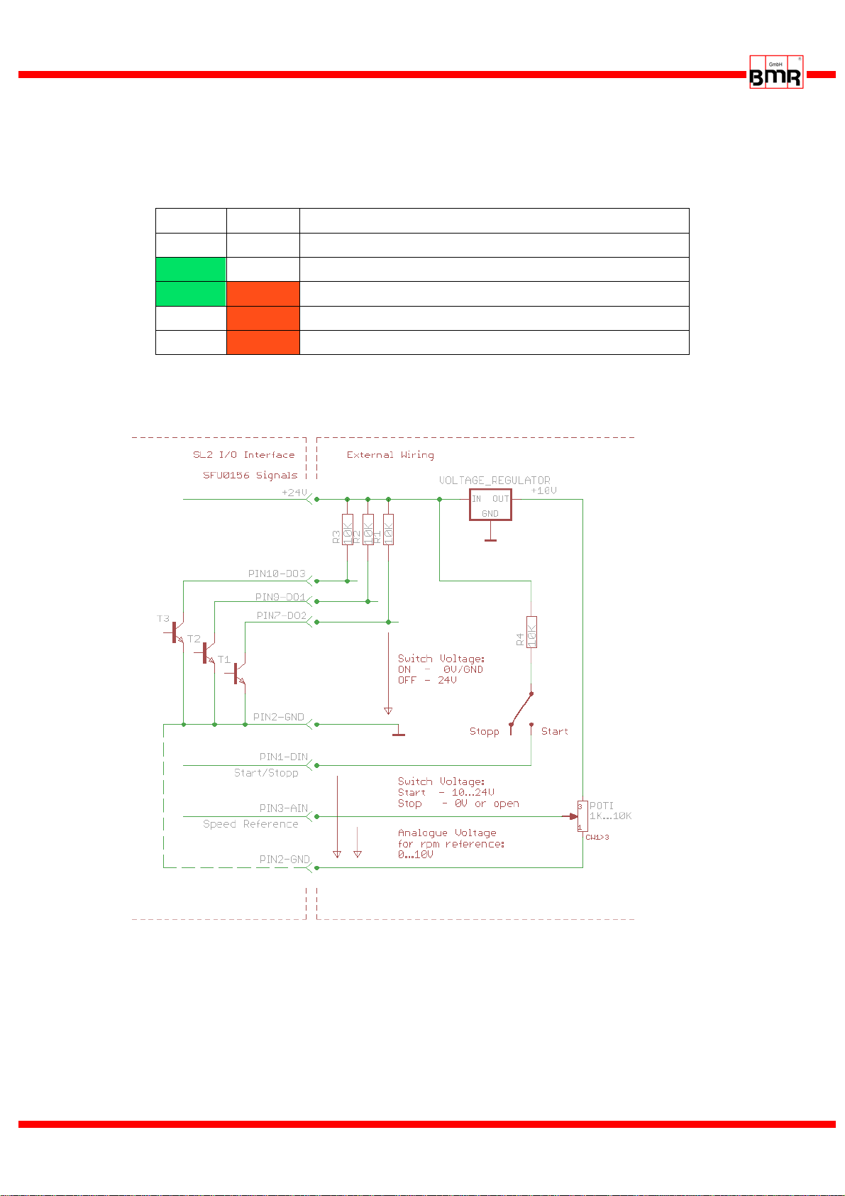
6. Example for I/O Wiring
example for wiring the I/O Interface
A successful start of the spindle the analogue voltage at PIN3 as reference for
the duty speed hast be higher than the minimum voltage (Æ5.2) .
With using a potentiometer for dialing the rotational speed it should be wired to
10V, so that the required range from 0…10V can be covered, representing the
speed range.
GREEN RED Function
Off Off Converter Not Ready
On Off Converter Ready
On On Overload or Error Warning
Off On Converter not Ready, Switch Off because of Error
Off blinking internal Error

SFU 0156 M a n u a l
E 2015-10-15
10
7. Safety Functions
The following safety functions bring about controlled stop of the spindle according
predefined deceleration times:
•Safety stop because of converter excess temperature after delay-time of 10s is exceeded
•Safety stop by overload and time delay exceeded (default 10sec)
•Safety stop will occur immediately by exceeding the maximum admissible spindle
current.
8. EMC
This device was developed for use in industrial environments. For trouble-free operation
and to reduce emitted interference, the following should be observed during wiring of the
equipment:
•The EMC of a machine or device is affected by all connected components (motor
spindle, length and type of cables, wiring, etc.). Under certain conditions the use of
additional filters can be necessary to maintain the current laws.
•The earth and shield connections of all those devices used in conjunction with the
frequency converter should be as short as possible and have as large a cross-section as
possible.
•Control devices used with the frequency converter (PLC, CNC, IPC) should be
connected to a common earth/earth terminal bar.
•Supply cables, motor cables and control cables must be completely isolated from each
other. Where crossing cannot be avoided, cables should be laid at 90° to each other.
•The control cable should be laid as far away as possible from the load cable.

SFU 0156 M a n u a l
E 2015-10-15
11
Green
Vout: 24V/120mA
Red
Vin: 28-95VDC
Blue
0V/GND
9. Power Supply Set (as Option)
As option a power supply set is available, consisting of a switched mode power supply
for the 48V and a DCDC voltage converter for the 24V supply. With the help of this set
it is possible, to generate the required DC-supply voltages for the SFU0156.
•48V Power Supply for Spindle Voltage Supply
Dimensions (WxHxD in mm): 115x50x216
•24V DC-DC Voltage Converter as separate solution
This DC-DC voltage converter generates the voltage for the 24V logic supply directly
from the spindle voltage. It has a wide band input range and a regulated 24V output.
Dimensions (WxHxD in mm): 20x15x30
Cable length: 160mm
0V / GND Mains connection
88-264 VAC
124-370 VDC
+48VDC Output

SFU 0156 M a n u a l
E 2015-10-15
12
48V Switched Mode Power Supply
24V Voltage Converter
SFU
•Connection Diagramm of Power Supply
(1) Cable Colours of the 24V Voltage Converter
•Version with onboard +24V logic supply
Attention: All these works handle with dangerous voltages and have to be
carried out by skilled persons only.
Please verify before connecting that the mains voltage is switched off!
24V/Green
(1)
Spindle Connector
48V
0V / GND
0V / GND
Blue*
48V / Red
(1)
Spindel spindle
connector
spindle- and logic supply
connector
on board +24V logic-
supply module

SFU 0156 M a n u a l
E 2015-10-15
13
10. SFU0156 with Remote Controller
On option a remote controller is available which can directly be connected with the
I/O interface at SL2.
By this, the required duty speed can be adjusted with a potentiometer and the
converter can be started and stopped with a rocker switch.
The status of the digital outputs is indicated on LEDs
All required voltages are generated within this adapter, so the converter can be
controlled and tested very easily.
A quick test and setting into action of the converter becomes possible even without
external control signals.
SFU 0156 M a n u a l
E 2015-10-15
14
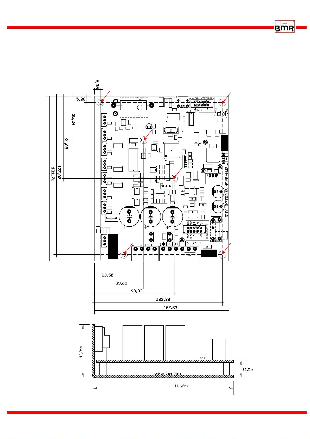
11.Drawing and Mounting
For mounting purpose there are 6 nuts with a 3mm thread provided, being pressed into
the at the bottom side of mounting bracket.
view from side
view from to
p

SFU 0156 M a n u a l
E 2015-10-15
15
this page is left blank intentionally

SFU 0156 M a n u a l
E 2015-10-15
16
Walpersdorferstr. 38
91126 Schwabach
Tel.: +49 (0)9122 63148-0
Fax.: +49 (0)9122 63148-29
Internet: www.bmr-gmbh.de
Subject to technical alterations.
2015-10-15
Other manuals for SFU 0156
1
Table of contents
Other BMR Media Converter manuals


