BMR SFU-0302-SSE User manual

Frequency Converter SFU-0302-SSE

SFU-0302 SSE M a n u a l – 2–
BMR GmbH 2014-03-17 E
Contents
1 Introduction
2 Description and Features
3 Block Diagram
4 Technical Data
5 Safety Precautions and Warnings
6 Connections, Interfaces and Pinout
6.1 Digital and Analogue Inputs and Outputs
6.2 Spindle Control Interface
6.3 Spindle connection at screw terminals
6.4 Mains Supply
6.5 RS232
6.6 Back Panel
7 Functions, Commissioning, Operation
7.1 Front Panel
7.2 LCD Display
7.3 Configuration via the Front Keys
7.4 RPM configuration
7.5 Starting and Stopping the Frequency Converter
7.6 Remote Controlled Configuration of Direction of Rotation
7.7 Safety Stop Functions
8 Connection to Profibus
9 Calibration and Configuration using Windows Software
10 Connection Examples
11 Faults, Trouble-Shooting
12 EMC (Electro-Magnetic Compatibility)
13 Mechanics, Views + Dimensions

SFU-0302 SSE M a n u a l – 3–
BMR GmbH 2014-03-17 E
1. Introduction
Depending on its construction, the speed of a three-phase a.c. motor is directly dependent on the
number of poles and the frequency of the network. In a 3ph 380V/50Hz network, with a 2-pole
motor, the rated speed would be 50 U/s * 60 = 3000 Upm.
With d.c. motors (brushless d.c.), the speed is dependent on the voltage applied.
Three-phase a.c. motors provide numerous benefits in industry, such as brushless operation,
freedom from wear and tear, favourable capacity/weight ratio, high-speed capability, and much
more. These motors can be used many different application areas, such as milling and grinding
spindles, or with drilling machinery, for example.
D.C. motors have the advantage of a high power efficiency (approx. 85%) when compared with
a.c. motors, but the disadvantage of not quite reaching the torque of an a.c. motor at low speeds
(when starting), nor reaching the high speeds of an a.c. motor. However, the higher efficiency
also means cooling requirements are lower and dimensions can be smaller.
In the aforementioned applications, three-phase a.c. motors are operated using special control
gear – frequency converters. These frequency converters convert the fixed 50 Hz network into a
3-phase network with variable frequency and voltage. This greatly reduces the start-up problems
and the high starting currents that are inevitable when high-capacity three-phase a.c. motors are
connected to a fixed network. The motor is controlled according to a special characteristic curve
until its rated speed has increased, or it has been braked to a standstill.
The frequency converter SFU-0302 -series has been specially designed for use in these high
frequency applications, offering excellent safety, performance and reliability, the result of years of
experience in the design and construction of frequency converters, together with the use of the
latest materials and the most reliable components. It can be used in many different applications
and is as equally suitable for use as a replacement device in existing systems with older type
series as it is in pre-planned applications as a cost-effective solution, helping to prolong the useful
life of tools. In addition, both a.c. and d.c. motors can be operated by this high frequency
converter.

SFU-0302 SSE M a n u a l – 4–
BMR GmbH 2014-03-17 E
2. Description and Features
•Operation of a.c. and d.c. motors/spindles
•The frequency converter SFU-0302 allows speed frequencies up to 180,000Upm with 2-pole
a.c. motors and 60,000Upm with d.c. motors.
•High output power ( 3,6kVA@230V / 2kVA@115V ) from a compact design
•The Kernel of the SFU-0302 is a Digital Signal Processor (DSP), which generates all output
variables and captures signals.
•All parameters, such as current, voltage and frequency, are captured in real time, and adjusted
by implementing via the Vector Control according to loading.
•Highly-accurate sinusoidal output signals with low harmonic distortion, facilitate the smooth
running of a.c. and d.c. motors/spindles under all operational conditions.
•The highest efficiency of motors at both low and high frequencies is made possible.
•High level of operational safety. All operating states such as acceleration, operation at rated
speed, and deceleration, are monitored and critical statuses are intercepted and brought under
control. This also includes the controlled deceleration of the motor / spindle in the event of
power failure or Emergency Stop.
•Integrated braking resistor for reduced external wiring.
•Transparency: The user is continuously informed of the status of the frequency converter and
the motor / spindle by means of a 4-column plain-text display on the front panel.
•Control: The frequency converter can be manually controlled and calibrated as required using 6
keys on the front panel.
•Individual adaptation to the application in hand and the spindle in use. Up to 16 different spindle
characteristics can be created and stored in the memory of the frequency converter, or existing
characteristics can be modified and adapted to the application.
•Diverse control and communication possibilities. 3 types of connection are available to
facilitate communication using peripheral devices - PC , PLC (Programmable Logic Control), CNC
(Computer Numeric Control).
•Straight-forward and flexible integration into existing systems by means of open configuration
of I/O signals for control and configuration:
Control inputs: 2 analogue, 6 digital
Control outputs: 2 analogue, 6 digital (relay)
•Galvanic separation of all interfaces from each other and from the network / motor potential
•Short-circuit-protected
•User-friendly configuration and control using optional Windows Software for the PC
•Automatic spindle detection, if supported by the spindle

SFU-0302 SSE M a n u a l – 5–
BMR GmbH 2014-03-17 E
3. Block Diagram

SFU-0302 SSE M a n u a l – 6–
BMR GmbH 2014-03-17 E

SFU-0302 SSE M a n u a l – 7–
BMR GmbH 2014-03-17 E
!
4. Technical Data
Supply connection 115V, 60Hz, 1PH 230V, 50Hz, 1PH
Output power Max 2 kVA Max 3,6 kVA
Motor connection 7-pole: U, V, W, PE, 2*PTC, SGND
Type: Amphenol C16-1 (fem. 6+PE) / Binder 693 (fem. 6+PE)
8-pole: U, V, W, 2*PE, PTC, FP, SGND screw terminals 4mm2
Output voltage 3* 115V 3* 230V
Output current Electronically limited
Over-current max. 10s
Output frequency AC: 3kHz / 180.000 rpm DC: 60.000 rpm
Spindle characteristics max 16, stored internally, freely definable
Spindle sensor inputs PTC, magneto-resistor, logic (D-Sub 15-pin fem. )
Control inputs 2 analogue: 0-10V, galvanically separated : (D-Sub 25-pin fem. )
Control inputs 6 digital: 0-24V, galvanically separated: (D-Sub 25-pin fem. )
Control outputs 2 analogue: 0-10V, galvanically separated (D-Sub 25-pin fem. )
Control outputs 6 digital: relay outputs, (D-Sub 25-pin fem. )
24VDC/1000mA, 125VAC/500mA
Interface RS232 galvanically separated, 9600Bd (D-Sub 9-pin male )
Housing dimensions width 130mm, height: 320mm (with mounting straps: 380mm), depth: 262mm
Weight 7 kg
Protection IP20
Operating conditions max. ambient temperature 40°C, no humidity
CAUTION: To avoid severe motor / spindle damage, select correct
motor / spindle characteristic !

SFU-0302 SSE M a n u a l – 8–
BMR GmbH 2014-03-17 E
5. Safety-Precautions and Warnings
•This device produces dangerous electrical voltages and is used for the operation of dangerous
moving mechanical parts. For this reason, only professionally trained and qualified personnel
should be allowed to install and repair this device!
•Before first activation of the device, verify, if it id in a faultless condition. If it was damaged during
shipping and transportation it must not be switched on.
•During installation the safety regulations have to be observed.
•Before the device is turned on for the first time, it should be verified, that the connected parts
cannot carry out uncontrolled movements.
•The frequency converter must not be operated close to heating devices or magnets or devices
generating strong magnetic fields.
•The maximum permissible ambient temperature of this device is from +41 °F till +104 °F.
•Sufficient air circulation around the converter should be ensured
•Fluids should be prevented from intruding into the housing. If it seems to be happened, the
converter has to be switched off immediately.
•The relative humidity must not exceed 90% (not condensed).
•The ambient air must not use aggressive, flammable or electrically conductive substances and
should be as free of dust as possible.
•All repairs and maintenance on the converter and the relating accessories must be carried out by
skilled personal and with powered off, only. To ensure this, the mains plug should be pulled out. In
doing this, both the terms of regulations for preventing accidents and the general and national
rules for mounting and safety have to be applied.
•The device must not be operated without properly connected PE connection and it has to be
verified that the mains connector is fixed with screws, if detachable.
•Maintaining EMC (electromagnetic compatibility) limits is the responsibility of the manufacturer of
the machine or device. The inputs and outputs on this device are fitted with filters, to increase the
interference immunity and reduce emitted interference, making it possible to use this device in an
industrial environment. The EMC of a machine or device is affected by all connected components
(cables, wiring, etc..) and for this reason, installation and connection of the device should only be
carried out by qualified personnel.

SFU-0302 SSE M a n u a l – 9–
BMR GmbH 2014-03-17 E
6. Connections, Interfaces and Pinouts
Operational parameters and outputs:
The SFU-0302 covers all current important operational parameters and operating data.
Up to 6 digital outputs can be used for signalling and up to 2 analogue values can be output to
the analogue outputs (0-10V) .
Remote Control and Outputs:
6 digital inputs (24V) and 2 analogue inputs (0-10V) are available for remote control of the
SFU-0302.
These assignments can be freely configured. Using the optional Windows PC software "SFU-
Terminal" the above assignments can be easily achieved, providing exceptional flexibility with
each application.
Each operating parameter can be assigned as a signal and each control signal can be allocated
the required I/O pin. In addition, the logic level (high or low active) can be individually defined.
The same assignment is also possible for the analogue measured data and control data at the
analogue I/O pin.
The standard allocations of operational parameters, their outputs, control signals and inputs, are
listed in the following table.

SFU-0302 SSE M a n u a l – 10–
BMR GmbH 2014-03-17 E
6.1 Digital and Analog I/Os (D-Sub 25pin fem.)
Pin Description Direction Function / User Message
1 Relay Common
14 Relay Common
2 Relay 1 Output
15 Relay 2 Output
3 Relay 3 Output
16 Relay 4 Output
4 Relay 5 Output
17 Relay 6 Output
5 Relay 1 NO contact Output
18 +24V/50mA Output auxiliary power supply
6 +24V/50mA Output auxiliary power supply
19 GND
7 GND
20 Relay 2 NO contact Output
8 Hall Sensor Output RPM-Signal from DSP
21 Digital In 6 Input
9 Digital In 5 Input
22 Digital In 4 Input
10 Digital In 3 Input
23 Digital In 2 Input
11 Digital In 1 Input
24 Analogue In 1 Input
12 Analogue In 2 Input
25 Analogue Out 1 Output
13 Analogue Out 2 Output
•The digital outputs (relays 1...6) are galvanically separated contacts (500VIsolation).
D.C.: 24V / 1000mA A.C.: 125V / 500mA
•Digital input switching level: "0" 0...7V "1" 18...24V
•The digital inputs require a high level of 24 V for correct function (PLC standard level).
•Hall sensor output level: 0-24V (24V level.)
•Analogue input voltage range: 0...10V
•The +24V output can be used as a power supply for this type of electronic spindle interface.

SFU-0302 SSE M a n u a l – 11–
BMR GmbH 2014-03-17 E
6.2 Spindle Interface for Control Signals (D-Sub 15pin fem.)
Pin Name Direction Function
1 NC
9 +5V/50mA Output for auxiliary power supply
2 GND
10 GND
3 Bit 0 Input automatic spindle detection
11 Bit 0 Input automatic spindle detection
4 Bit 1 Input automatic spindle detection
12 Bit 1 Input automatic spindle detection
5 Bit 2 Input automatic spindle detection
13 Bit 2 Input automatic spindle detection
6 Bit 3 Input automatic spindle detection
14 Bit 3 Input automatic spindle detection
7 PTC Input Temperature Signal from Spindle
15 PTC Input Temperature Signal from Spindle
8 Hall sensor Input RPM-Signal from Spindle to DSP
•The spindle interface is completely isolated by optocouplers. It can be used for automatic spindle
detection, if enabled.. To set a high level to one bit, a simple connection to the spindle GND is
made. An open contact equals low level. The direction of high/low active can be changed in the
form ‘digital inputs’.
•The PTC input detects over-temperature of the spindle. A high resistor value at this pin of >600
Ohms causes the switching of digital output overtemp spindle and safety cut-out following the
programmed delay .
•The Hall sensor input operates from input signal levels of +/- 1V within the common mode range
of 0..10V.
•The 5V output can be used as a power suppl.

SFU-0302 SSE M a n u a l – 12–
BMR GmbH 2014-03-17 E
!
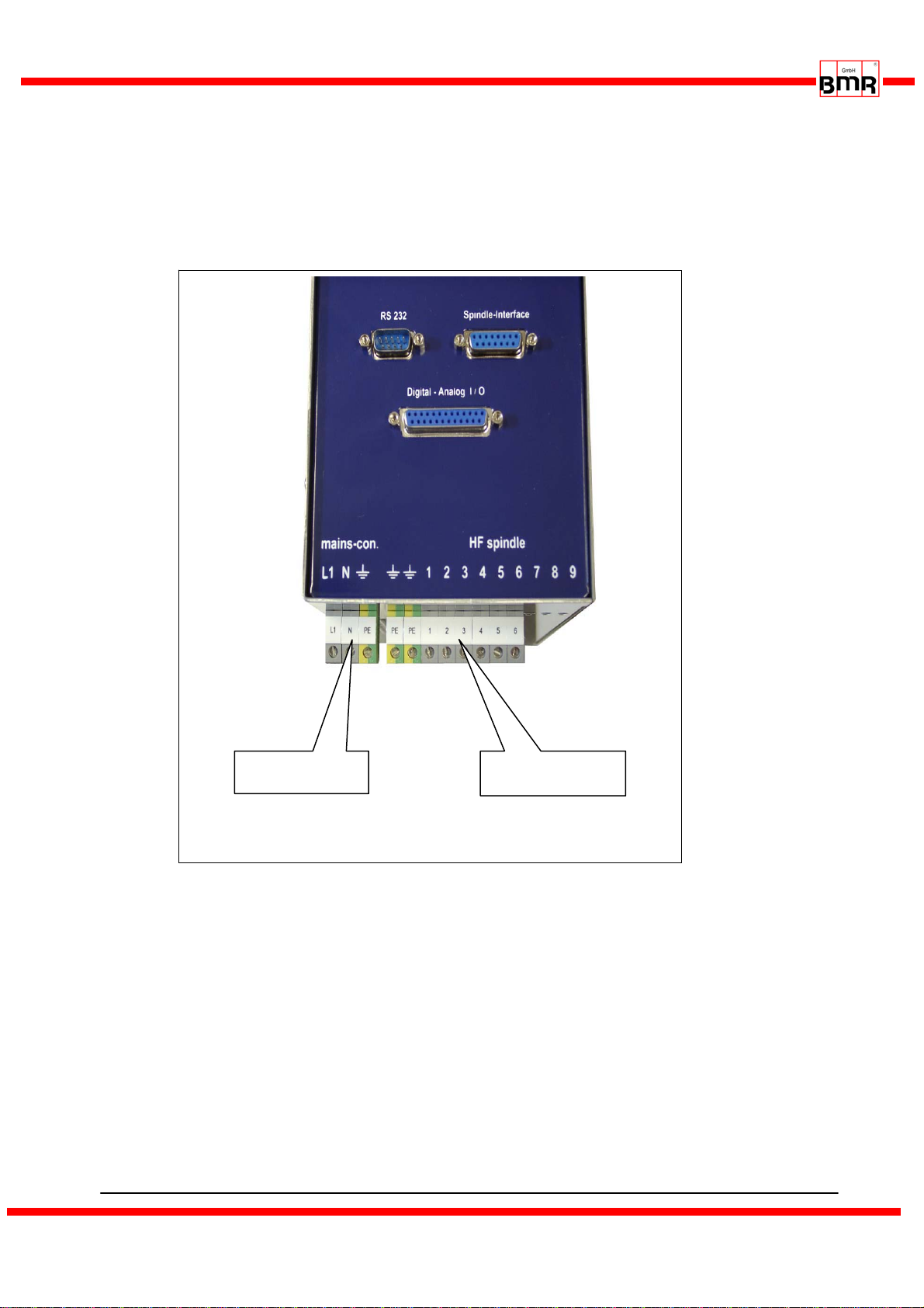
6.3 Spindle connection at screw terminals
PE Earth Protection GND
PE Earth Protection GND
USpindle Phase 1
VSpindle Phase 2
WSpindle Phase 3
SGND Signal-GND for FP- and PTC-Signals
FP Hall-Sensor-Signal (Spindle speed)
PTC PTC-Signal (Spindle Temperature)
6.4 Mains
Control cables, supply cables and motor cables must be isolated
from each other. Shielded cables are to be preferred !
6.3 RS232 (D-Sub 9pin male)
Pin Description Function
2 RxD receive-data (data to converter)
3 TxD send-data (data from converter)
5 GND Ground
use a standard zero-modem-cable for connection to PC
PE
PE U V PTC FP SGND
W
-
-
1
3
4
5
6
2
L1
N
PE
L1 Mains L1
N Neutral N
PE Earth Protection GND
SFU-0302 SSE M a n u a l – 13–
BMR GmbH 2014-03-17 E
6.5 Screw Terminals
figure1
Mains Spindle screw
te
rmin
a
l
s

SFU-0302 SSE M a n u a l – 14–
BMR GmbH 2014-03-17 E
7. Functions, Commissioning, Operation
3 operational possibilities:
•Control and configuration manually via front keys
•Automatic control and configuration via PLC / IPC
•Automatic control and configuration via PC (RS232 interface)
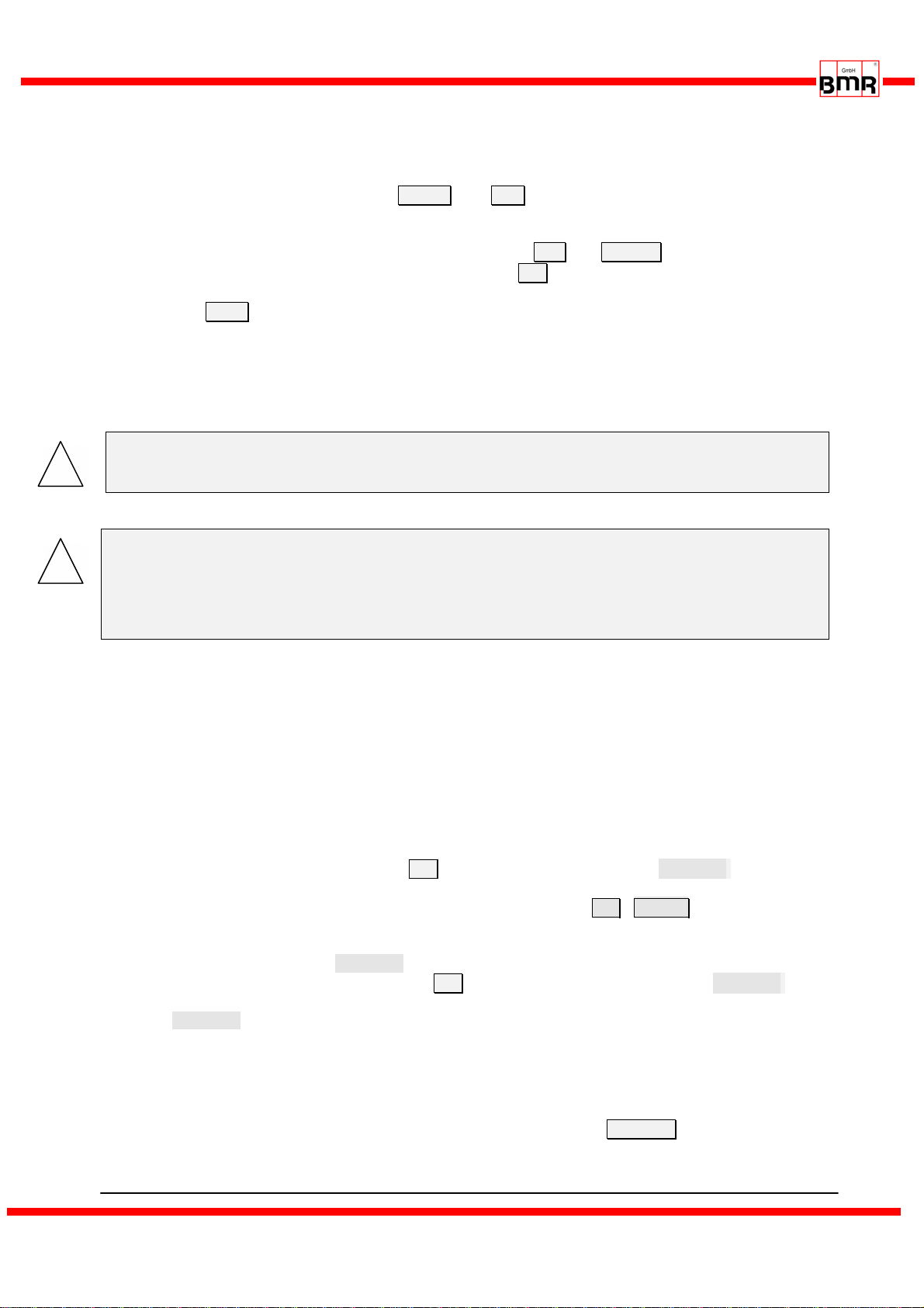
7.1 Front Panel
figure2
The front keys allow access to following functions:
•Start / Stop manually
•RPM-control via UP / DOWN keys
•Spindle characteristic selection
Button UP
Button DOWN
LCD 4-rows
Button START
Button STOP

SFU-0302 SSE M a n u a l – 15–
BMR GmbH 2014-03-17 E
7.2 LCD-Display
All system data and parameter such as RPM, load or errors will be displayed on the LCD-display.
The actual load output is displayed by bargraph and absolute in % in the bottom line of the
display.
The pre-selected duty RPM and spindle characteristic and the actual RPM of the spindle is
displayed
converter is running spindle characteristic 3
converter is in Stop State > spindle standstill
converter is accelerating
power output 67%
converter is accelerating
power output 34%
spindle is rotating at duty RPM
power output 20%
Errors are displayed in the top line by text.
Ifanerrorisdetected,thisisindicatedbythemessage conv. not ready !
and with an error-message in the first line.
list of possible error-messages
•Erroroverload Overload Stop
•Error overload of converter Overtempe ra tu re!
•Error overtempertature of the spindle Overt em p Sp in dl e
•Error overtemperature of converter and spindle Overtem p cnv+sp !
•Error overvoltage Over vo ltage stop
•Errorundervoltage Undervolt. out
•Error undervoltage Stop Undervolt. stop!
•Error powerstage disabled PW Rsta. di sa bl ed
•Error shutdown enabled Stop state !
•Error no spindle or spindle-line break noSpindle-c ab le ?
•Error timeout ser. interface RS232 Error !
•Error spindle characteristic not valid Data Er ror: !
•Errorencoder/hallsensor Encoder error: !
S t o p s t a t e ! 3
F o r w > 2 5 0 0 0 R p m
O u t p . 2 5 0 0 0 R p m
C o n v r e a d y !
d u t y R P M r e a c h e d 3
F o r w > 2 5 0 0 0 R p m
O u t p . 2 5 0 0 0 R p m
_ _ _ _ _ _ _ _ _
_
2 0
3
F o r w > 2 5 0 0 0 R p m
O u t p . 1 9 2 4 0 R p m
_ _ _ _ _ _ _ _
3
F o r w > 2 5 0 0 0 R p m
O u t p . 7 8 3 0 R p m
_
O v e r l o a d 3
F o r w > 2 5 0 0 0 R p m
O u t p . 2 5 0 0 0 R p m
c o n v. n o t r e a d y !
SFU-0302 SSE M a n u a l – 16–
BMR GmbH 2014-03-17 E
!
!
7.3 Configuration via the Front Keys
Menu settings can only be adjusted when the device has come to a complete standstill.
By simultaneously pressing the keys STOP and OK , the Menu Spindle Characteristic
Setting will appear:
Select the number of the spindle characteristic using the UP and DOWN keys.
Accept and activate desired characteristic by pressing OK.
The display will indicate whether the spindle characteristic is valid or not (check sum...., data)
Exit with ESC without selection
Spindle Characteristic :
•Standard: A number of spindle characteristics are already implemented. Existing
characteristics can be loaded and displayed using the PC software "SFU-Terminal".
•Variants for HPT motors: all spindle characteristics for HPT-Motors are implemented ex-works.
CAUTION: To avoid severe motor / spindle damage, select correct
motor / spindle characteristic !
Where several spindles are in use within one system, the user must ensure
use of the correct spindle characteristic number to prevent spindle damage
( different spindle types may have different line voltages !)
The LCD shows all relevant system messages for speed, load or errors.
In the event of an error, the error type is displayed in plain text.
7.4 RPM configuration
(all references to menues relate to setup software SFU-Terminal)
The preset of revolutions per minute of the spindle can be achieved by two ways:
•Preset manually via panel keys
In form 'Analogue Inputs'option button 0V has to be enabled in the line of duty RPM . (no
analogue input is assigned to this function)
The duty RPM is displayed on the LCD and can be changed with UP / DOWN (holding a key
down increases the count rate). RPM can be changed during operation
•Preset via analogue input duty RPM
In menue 'Analogue Inputs' option button 0V has to be disabled and the function duty RPM .
has to be assigned to an analogue input. Additionally a scaling has to be selected from the list
box duty RPM (e.g.: 1V/10.000RPM)
The value of the duty RPM is displayed on the LCD according to the scaling and the voltage at
the input. A voltage of 0V leads to a standstill and a voltage higher than 0V leads to a startup upto
the desired revolution. An input voltage of 4V and a scaling as above mentioned lead to a
revolution of 40.000RPM.
The settings must be downloaded into the converter with the button write data.

SFU-0302 SSE M a n u a l – 17–
BMR GmbH 2014-03-17 E
!
7.5 Starting and Stopping the Frequency Converter
(all references to menues relate to setup software SFU-Terminal)
There are different methods of starting and stopping SFU-0302 frequency converters, due to
many different requirements, as follows below:
•manually via panel keys
•Remote control via digital input
•Remote control via analogue input
•Remote control via serial interface
Before starting the converter is possible, a preset of the RPM (> 7.4) has to be done. This is
necessary for all options of starting with the exception of analogue starting.
•Manually via panel keys
Activation of spindle start via the green START key.
Spindle-stop is activated by the red STOP key on the operator panel.
•Remote control via digital input Start/Stop by external PLC or CNC
Digital Input 1 is the default. To change this, click on themenue ‘digital inputs’ .The correct
spindle characteristic can be preset here also.
Depending on your safety regulations, you can program this individually and set high or low active
signals. In general, when using SPS control, it is best to set safety cut-outs at low-active, so that
the machine will stop should a cable or connector defect occurs.
•Remotely via the analogue input
Analogue starting will be enabled where at least one of the analogue inputs in the menue
'analogue inputs' is selected and a valid signal at the digital input Start/Stop is present.
Additionally a scaling has to be selected from list-box duty RPM of analogue value to RPM.
•Remotely via the RS232 serial interface from a PC or PLC .
The speed pre-selected from the panel is taken as the required speed in this instance. Speed can
be altered via commands from the RS232 interface.
The RS232 interface offers complete control of the SFU-0302 converter via the optional full-
version Windows platform. The level of control this provides is almost at machine-level, so that
this option is more appropriate for error evaluation and special control features via PC. If you
need to control the SFU-0302 remotely, please contact BMR or your local distributor for
assistance and the RS232 command-set.
Where one of the above options has been selected to operate the converter, only that pre-
selected option can then be used to stop the converter! Only one of the safety functions can
override the operation.
7.6 Remote-Controlled Configuration of Direction of Rotation via Digital Inputs
Via digital input RPM direction . Setup is carried out in menue ‘digital inputs’. This is necessary,
if the direction of rotation has to be controlled , for example, via a PLC. Reversal can only take
place once the spindle / motor has come to a complete stop. If the direction pre-selection setting
is changed whilst the spindle / motor is running, the spindle / motor will not turn in the new
direction until it has been brought to a complete standstill and then restarted.

SFU-0302 SSE M a n u a l – 18–
BMR GmbH 2014-03-17 E
7.7 Safety stop functions
As shown above, all these safety and start-up features are programmable and a digital input pin
or logical behaviour of this pin (high-, low-active) can be selected.
The following safety functions bring about controlled stopping of the machine, pre-defined by the
deceleration times selected within the spindle characteristics,
•Safety stop by spindle overtemperature, if this function is activated and it's delay-time exceeded
In form 'Spindle' this function can be enabled with the check button Temp. sense and in form
'delays' the delay time can be specified.
•Safety stop by converter over-temperature and delay-time exceeded, specified in the form
'delays' (accessed by delays button)
•Safety stop by overload and time delay exceeded (determined by maximum current and voltage
in the spindle diagram and the form 'delays', accessed by delays button)
•Immediate safety stop by over-current of the converter.
•Safety stop by emergency stop through digital input shutdown in form ‘digital inputs’
The following stopping methods shut off the power stage and the spindle will slow down only
though its own load. This process can take up to ten minutes until the spindle has fully stopped:
•Safety stop via short-circuit protection on digital input PDP Interrupt determined by internal
converter current limit.
•Safety stop by digital input PWR stage off in the form ‘digital inputs’.
After an error flag has occurred, it must be cleared by a Start/Stop sequence or a digital error
reset with a digital input (in form ‘digital inputs’ Error reset). 4 seconds after error reset, the
device is ready for operation again.

SFU-0302 SSE M a n u a l – 19–
BMR GmbH 2014-03-17 E
8. Connection to Profibus
As option for communication with CNC a Profibus DP Interface is available. The physical
connection is realized by a standard RS485 Interface. With the help of a USB-RS485 converter
(e.g. from Meilhouse) communication to SFU-Terminal software(see 9.) is possible as usual.
After having installed a specific windows hardware driver for USB-RS485 converter on the PC
which emulates a virtual com port, SFU-Terminal Software V2.0 and higher will detect RS485 and
establish communication automatically.
The relevant files plus command interpreter for integration for example into Siemens S7, are
available under Support/Download/BMR-GSD.
The setup of address of station is carried out either Online with the help of SFU-Terminal and the
listbox Profibus Address, or Offline: Pressing Start and Stop key simultaneously during PowerOn
will show a selection menu. The address can be changed in the range of 0..126 with the Up-
Down keys. Storing and returning to operating mode with ESC-key
Special Features of Profibus Version:
For controlling is carried out completely digitally, some features are eliminated. Analogue input
function for rotational speed and the output of analogue values aren't available no longer.
Analogue input and output can be done via Profibus. With the help of a pointer any value can be
addressed. Please see the documentation of command interpreter Profibus in folder BMR-GSD.

SFU-0302 SSE M a n u a l – 20–
BMR GmbH 2014-03-17 E
9. Configuration with Windows-Software
The software "SFU-Terminal " is an optional tool used to configure all frequency converters
0102...0601 and also provides the possibility of user-friendly data display and calibration,
implemented as follows:
1. Start-up frequency converter and connect via RS232 interface.
2. Start-up program SFUTerminal.exe
The interface is then configured automatically. A connected frequency converter is detected
and all data transfer parameters are synchronised.
The description can be found in the help menu and manual of "SFU-Terminal".
Table of contents
Other BMR Media Converter manuals


