BMR SFU 0303/4 User manual
…when it comes to quality! BMR GmbH
1

2
SFU 0303 F equency Conve te

…when it comes to quality! BMR GmbH
1
Issue
Mai 2017
1
Int oduction
2
2
Desc iption and Featu es
4
3
Block Diag am
5
4 Technical Data
6
5
Safety P ecautions and Wa nings
8
6 Connections, Inte faces and Pinout 9
7 Functions, Setup, Ope ation
18
4.1
Ve sion SSE
6
4.2 Ve sion 19“ and Desktop
7
6.1
Digital and Analogue Inputs
and Outputs
10
6.2 Spindle Inte face X4 11
6.3 Ve sion SSE: Mains Connecto , Spindle Connecto 13
6.4 Ve sion 19“: Mains Connecto , Spindle Connecto 14
6.5 Ve sion Desktop: Mains Connecto , Spindle Connecto 15
6.6 Ve sion SSE: RS232 17
6.7 USB-Connecto 17
8 Setup with Windows-Softwa e 27
9
Automatic Spindle Tuning
28
10
Examples fo Connection
30
11
EMC
32
12
T oubleshooting
33
7.1
F ont panel of SSE, Desktop und 19“ Ve sion
1
8
7.2 Conve te Sta t and Stop 19
7.3 Status LED Display 20
7.4 LCD-Ope ating Panel 21
7.5 Sta t and Stop 26
7.6 Setup of Rotational Speed 26
7.7 Safety Functions 26
11.1
Mains and Spindle Connection
3
1
11.2 Logic and Wi ing fo Safety 32
13
Gene al Hints
37
14
Wa anty
38
15
Accesso ies
39
16
Mechanics and Dimension
40
1
6
.1
SEE Ve sion fo cabinet m
ounting
4
0
16.2 19" Ve sion
41
16.3 Desktop Ve sion
42
16.4 Desktop 63TE Ve sion 43
17
Othe p oducts of BMR GmbH 44
18
Ou Quality Commitment
45

2
SFU 0303 F equency Conve te
1. Int oduction
Due to its construction, the rotational speed of a 3-phase AC motor is directly dependent on
the frequency of the voltage and the number of poles. In case of a 3P 50 z voltage and a
2-pole motor, the nominal speed would be 50 rps * 60 = 3000 rpm.
In case of BLDC motors (brushless dc), the speed is directly dependent on the voltage applied.
3-phase AC motors provide numerous benefits in industry, such as brushless operation,
freedom from wear and tear, favorable capacity/weight ratio, high-speed capability, and
much more. These motors can be used many different application areas, such as milling and
grinding spindles, or with drilling machinery, for example.
The advantages of SFU0303 compa ed to simila conve te s:
Safe Power Stage Pulse inhibitor, authorized to current regulations EN 954_1 Cat 3
Maximum Power in industrial network up to 5kVA
igh efficiency by symmetrical PWM
Real time vector control for sensorless operation
Maximum Torque even at lowest rotational speeds
igh possible acceleration rates for short process times. For example 25.000rpm/sec
with a 2,2 KW Motor (with robotic applications)
Pulse-Amplitude (PAM / =Block-Modus ) Control possible because of regulated
intermediate voltage control (on option)
Very slow rotational speeds (10rpm) possible for reaching tool changer positions.
Very low current consumption because of real time power control
Easy Integration into new and existing PLCs because of flexible I/O configuration
Various interface options: RS232, USB
Easy reversing the direction of rotation by Software without loss of power.
Autotuning function for spindle setup.
Testrun with graphical documentation of voltages and currents of the spindle
Up to 16 different spindle characteristics can be stored
Very user-friendly debugging interface for setup control

…when it comes to quality! BMR GmbH
3
Start/Stop Interface for periodical tests or remote control
Operating panel is detachable and can be used as remote control together with an extension
cable
Designed for roughest use in industrial environment
The housing of SSE is realized without ventilations slots and an outside mounted heatsink.
preventing by this the intrusion of dirt and chips of tooling.
Very compact case style makes easy cabinet mounting possible
Several case options for cabinet mounting (SSE) , 19" rack style and desktop, or special designs
on request
User friendly Screw-plug connector system for power-, spindle- and I/O connectors.
Wide range of operating voltage 115V-230V
Automatic deceleration of the spindle down to standstill in case of mains failure by "Back
Energy" Function
Plain text display in amber color
Very user friendly operation menu.
USB connection and RS232 with specific adapter cable
Full functional without operation panel in remote configuration
Remote control hand-terminal available
Controlled fan
Datalogger-Function on option available in combination with PC software SFU-Terminal.
Records of all relevant parameters of the converter in nearly infinite lengths are possible
down onto the PC- hard disc.

4
SFU 0303 F equency Conve te
2. Desc iption and Featu es
Operation of Asynch onous AC und BLDC Motors
The high frequency converter SFU-0303 makes possible output f equencies 3.3 kHz / 200.000 Upm
with 2pole AC-Motors and with BLDC-Motors up to 100.000 pm
High output powe ( 3,6kV @ 230V / 2kVA @ 115V ) in compact style
The core of SFU-0303 is a Digital Signal P ocesso (DSP) which produces all output signals and collects
all input signals
All parameters like current, voltage and frequency are collected in eal time and are regulated by the
implemented vector control depending on the load condition.
High p ecision sinusoidal output signals with low distortion factor realize very high accuracy in true
running behavior.
Allows highest efficiency of the spindles at low and high f equencies
igh ope ational safety: All operating conditions like acceleration, operation with nominal rotational
speed, deceleration is monitored and critical conditions are intercepted.
Integ ated b aking esistance (b ake choppe ). Without brake chopper the deceleration times down
to standstill can be longer.
T anspa ency: The user is always informed about the current status of the converter and the spindle
on a plain text and detachable operating panel at the front panel.
Cont ol: If needed, the converter can be controlled and parameterized manually with a pluggable
operating unit.
Easy eve sing the di ection of otation by Software without loss of powe .
Individual adjustment to the current application and the connected spindle. Up to 16 different
characteristics can be stored in the converter
A va iety of options fo cont ol and communication possibilities: For communication with peripheral
devices, such as PC, PLC or CNC, there are 3 ports available:
Easy and flexible integ ation into existing equipments by free configuration of I/Os
Control inputs: 2 Analog, 6 Digital
Control Outputs: 2 Analog, 6 Digital (Relay)
Galvanic sepa ation of all interfaces from each other and from mains / spindle potential
Sho t ci cuit p oof
Comfo table Configu ation und control with the help of a PC-Windows software "SFU-Terminal"
Cloning-Function with ope ating panel: Creating of clones of converters by individual read out of the
SFU-parameters into the operation panel and download into another or multiple SFUs.
Automatic spindle calibration by autotuning function

…when it comes to quality! BMR GmbH
5
3. Block Diag am

6
SFU 0303 F equency Conve te
4. Technical Data
4.1 Ve sion SSE
ATTENTION
The ope ation of a spindle with a w ong cha acte istic may ha m the spindle
seve ely!
Please ensu e to have the p ope cha acte istic selected always!
Mains connection 115V, 60 z 230V, 50 z
Continuous output power 2 kVA 3,6 kVA
Motor connection
Output voltage 110V 220V
Output current / power
Output-current
Output frequency
Spindle characteristics
Spindle sensor inputs
Control inputs
Control inputs
Control outputs
Control outputs
Interface
Dimensions
Weight
Protection
Operating conditions
2 Analog: 0-10V, separated galvanically
5 - 40°C / rel. umidity of air max. 85%
IP20
- USB on operating panel (USB-Mini)
- RS232, (
9 pin DSub male
)
2 Analog: 0-10V, separated galvanically
6 Digital: 0-24V, separated galvanically
10-polig: PE, U, V, W, PTC, FP, SGND
pluggable screw terminals 4mm²
limited electronically
5 x Digital, free to be setup
outputs on Relays, 24VDC/1000mA, 125VAC/500mA
see chap 17
ca. 4 kg depending on option
PTC, Speed sensor / all sensor, Logic
maximal duration adjustable 0 … 20sec
AC: max 2,2k z / 200.000 rpm
DC: max 1.667 z / 100.000 rpm
max. 16, stored internally

…when it comes to quality! BMR GmbH
7
4.2 Ve sion 19", Desktop and Desktop 63TE
Mains connection 115V, 60 z 230V, 50 z
Output power max. 2 kVA max. 3,6 kVA
Motor connection
Output voltage 110V 220V
Output current / power
Output-current
Output frequency
Spindle characteristics
Spindle sensor inputs
Control inputs
Control inputs
Control outputs
Control outputs
Interface
Dimensions
Weight
Protection
Operating conditions
13-pin: U,V,W, PTC, FP, SGND, Shield, PE
circular connector
limited electronically
5 x Digital free to be setup
output on relays, 24 VDC/1000mA, 125VAC/5000mA
25pin D-Sub female
see chap 17
approx. 4 kg depending on option
PTC, Speed sensor / all sensor, Logic
maximal duration adjustable 0 … 20sec
AC: max 3,3k z /200.000 rpm
DC: max 100.000 rpm
max. 16, stored internally
2 Analog: 0-10V, separated galvanically
5 - 40°C / rel. umidity of air max. 85%
IP20
- USB / - RS232
to be used alternatively
2 Analog: 0-10V, separated galvanically
5 Digital: 0-24V, separated galvanically
ATTENTION
The ope ation of a spindle with a w ong cha acte istic may ha m the
spindle seve ely!
Please ensu e to have the p ope cha acte istic selected always!

8
SFU 0303 F equency Conve te
5. Safety- P ecautions and Wa nings
This device produces dangerous electrical voltages and is used for the operation of fast
spinning tools. Because of their high rotational speed, it may be dangerous in case of
improper handling. For this reason, only professionally trained and qualified personnel
should be allowed to work with and setup this device!
Before the first commissioning can be carried out, it should be ensured that the spindle and
the tool are fixed properly, to eliminate all dangers because of uncontrolled movement of
the spindle.
Safety regulations being valid for the country where the device is used, have to be adhered
to where any work is carried out on the device.
Before the device is turned on for the first time, it should be verified, that the connected
parts cannot carry out uncontrolled movements.
The frequency converter must not be operated close to heating devices or magnets or
devices generating strong magnetic fields.
Sufficient air circulation around the converter should be ensured.
Fluids should be prevented from intruding into the housing. If it seems to be happened, the
converter has to be switched off immediately.
The ambient air must not use aggressive, flammable or electrically conductive substances
and should be as free of dust as possible.
All repairs and maintenance on the converter and the relating accessories must be carried
out by skilled personal and with powered off, only. To ensure this, the mains plug should be
pulled out. In doing this, both the terms of regulations for preventing accidents and the
general and national rules for mounting and safety have to be applied.
Do not open this device while it is connected to power supply. There is danger of life!
With opening this unit the period of warranty will be ended.
All people who work with this device should be trained and instructed by their line advanced
technician.
Attention:
Please ve ify that all powe supply voltages a e co ect in pola ity and value.
Attention:
Please ensu e to have the p ope cha acte istic selected, always!
The ope ation of a spindle with a w ong cha acte istic may ha m the
spindle seve ely!
Attention:
In case of eplacing the fuses, please ensu e to use types only, which a e
mentioned in 'Technical Data'!

…when it comes to quality! BMR GmbH
9
6. Connections, Inte faces and Pinouts
For embedding into PLC and controls the SFU0303 has several input and outputs.
They are realized as pluggable screw terminals and are located at the front or rear panel
(depending on case option). All contacts are separated galvanically from high voltage carrying
circuits.
Operational parameters and outputs:
The SFU-0303 captures all current important operational parameters and operating data.
Up to 6 digital outputs can be used for signaling and up to 2 analogue values can be output to
the analogue outputs (0-10V).
Remote Control and Outputs:
6 digital inputs (24V) and 2 analogue inputs (0-10V) are available for remote control of the
SFU-0303.
These assignments can be configured freely. By using the optional Windows PC software
"SFU-Terminal" the above mentioned assignments can be achieved easily, providing
exceptional flexibility with each application.
Each operating parameter can be assigned as a signal and each control signal can be assigned
to a certain I/O pin. In addition, the logic level (high or low active) can be individually defined.
The same assignment is also possible for the analogue measured data and control data at the
analogue I/O pin.
The standard allocations of operational parameters, their outputs, control signals and inputs,
are listed in the following tables.

10
SFU 0303 F equency Conve te
6.1 Digital and Analog Inputs and Outputs
(25 pin D-Sub female)
Version SSE on front panel
19", Desktop, Desktop 63TE on back panel
Pin Desc iption Di ection Function / Default
1 Relay Common Common Rail relay 1-5
9 Relay 5 normally closed Output Standstill Conve te + Spindle
2 Relay 2 normally open Output Duty Speed Reached
10 Relais 4 normally closed Output Ove load > 100%
3 Relais 3 normally closed Output Ove tempe atu
11 Analog In 1 Input Duty Speed Input
4 Analog Out2 Output
depending on the ype of device:
- DC Out current speed of spindle 1V/10.000rpm
- DC Out output load 0…12V = 0…120%
12 Analog Out 1 Output Ref. Value Duty Speed Output
5 Digital In 1 Input Inversion of Direction of Rotation DRU high active
13 RS232 RxD Input
6 Relais 1 normally open Output Ready / Conve te Ready
14 RS232 TxD Output
7 all Sensor Output Processed rectangular signal of speed sensorr
15 Digital In 2 Input Emergency Stop / Converter Locking
…when it comes to quality! BMR GmbH
11
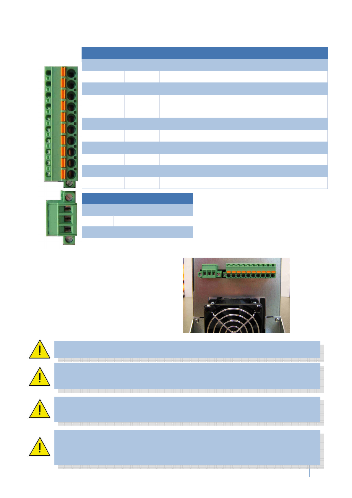
6.2 Ve sion SSE: Mains and Spindle connection
View at sc ew te minals at ve sion SSE:
Pin Name Di ection Function
1 +VFP Output Auxiliary voltage supply for active speed sensor 12V/50mA
2 SGND Ground reference for signals FP, PTC
3 FP Input Input for 2/3-wire speed sensors / all sensor
4PTC Input temperture signal of the spindle or as option KTY setting
via interface X4-Pin3 -> 6.3
5 W Output Spindle Phase W
6 V Output Spindle Phase V X4
7 U Output Spindle Phase U
8 Rext Output External Brake resistor / Chooper Resistor
9 +ZU Output Intermediate voltage (! Attention, igh Tension!)
10 PE Output Connection for protective earth of spindle ! Safety !
+VFP
SGN
D
FP
PTC
W
V
U
Rext
+ZU
PE
L
N
PE
Name Function
PE protective Earth ! Safety
!
N Null
L Phase
The device has no inte nal fusing. It has to be fused exte nally
Please ensu e, that PE p otective ea th is connected at the mains side. The
device must not be ope ated without p ope ly connected PE!
Please ensu e, that PE p otective ea th is connected at the spindle side as
well as at the mains side.
Cont ol wi es, Mains cables and spindle cables should be installed
sepa ately.
Fo wi ing, the use of shielded cables is ecommended.
+VFP
SGND
FP
PTC
W
V
U
Rext
+ZU
PE
PE
N
L

12
SFU 0303 F equency Conve te
6.3 19" Ve sion: Mains and Spindle connection
Back side SFU0303-19" with spindle connector clamp terminal
Spindle Connecto - 9pin clamp te minal
Mains connection - 3pin clamp te minal:
Spindle connection
Spindle Interface
I/O Interface
Mains Connection
Automatic Fuses
automatic thermal fuse
Pin Name
Di ection Function
1 +VFP Output Auxiliary voltage supply for active speed sensor 12V/50mA
2 SGND Ground for signals FP, PTC
3 FP Input Input for two/three wire-speed sensors
4 PTC/KTY Input
Temperature signal from spindle or as option KTY
setting on spindle interface Pin1 ->6.6
5 W Output
Spindle Phase W
6 V Output Spindle Phase V
7 U Output Spindle Phase U
PE PE
PE PE Connection for protective earth of the spindle ! Safety !
Name Function
PE protective earth ! Safety !
N Neutral
L Phase
Please ensu e, that PE p otective ea th is connected at the mains side. The device must not
be ope ated without p ope ly connected PE!
Please ensu e, that PE p otective ea th is connected at the spindle side as well as at the
mains side.
Cont ol wi es, Mains cables and spindle cables should be installed sepa ately.
Fo wi ing, the use of shielded cables is ecommended.
…when it comes to quality! BMR GmbH
13
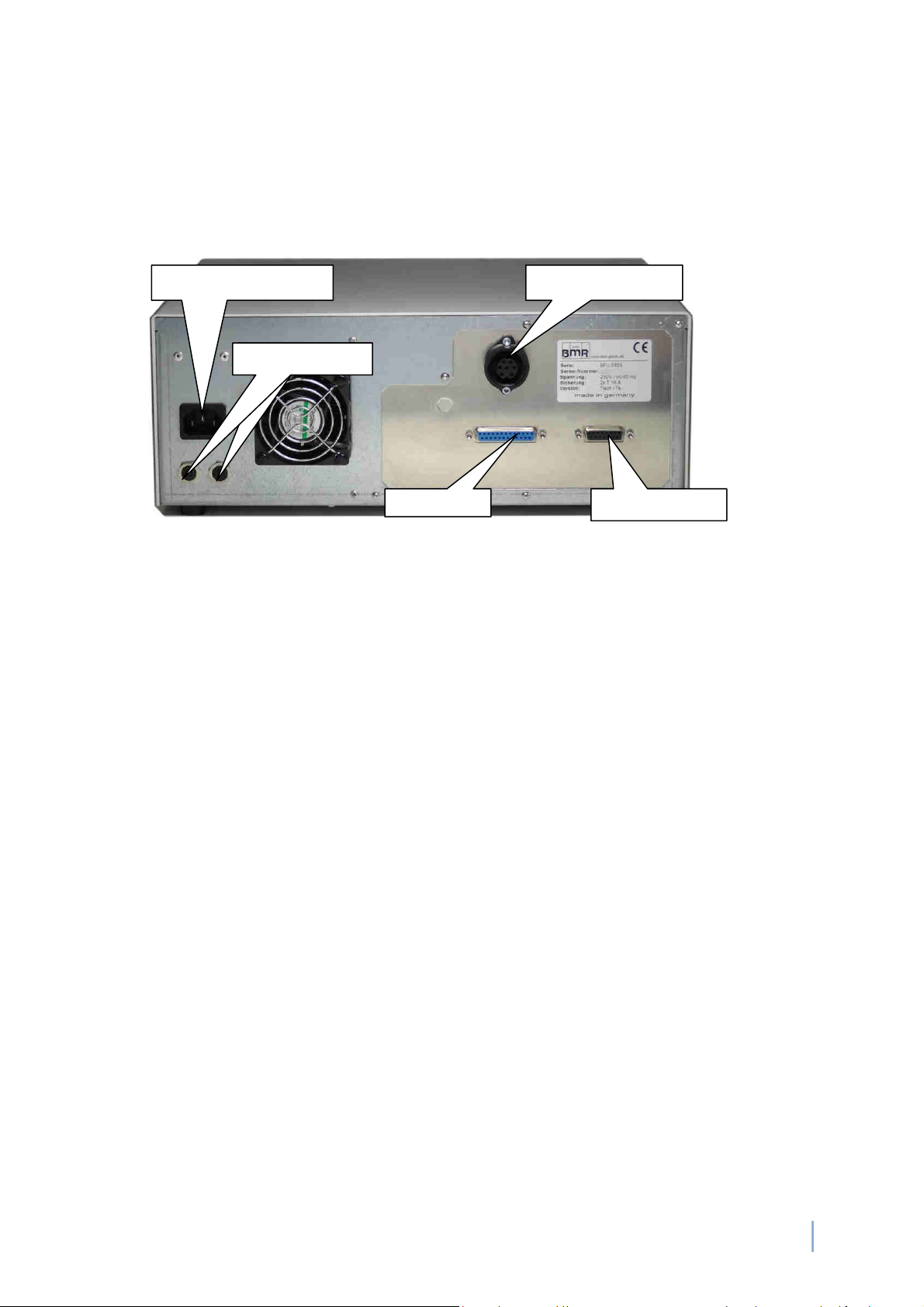
6.8 Desktop Ve sion: Mains and Spindle Connection
The connection with mains network is carried out with an IEC connector
The device is equipped with a Thermo-Automatic Fuse for each prong. They can be reset after
tripping by pressing down the button
The spindle connection is realized on custom order and can be realized accordingly
Backside SFU0303-Desktop equipped with a 7pin circular spindle connection
IEC Mains connection
Sicherungsa
Automatic Fuse
I
/O Interface
Spindle Interface
Spindle connection

14
SFU 0303 F equency Conve te
Spindle Connection
7pin female Binder Series 693 or Amphenol C16-1
Spindle Connection
13pin female Binder Series 694
Pin Name Desc iption
6 SGND Signal GND for PTC-and FP Signal
5 W Spindle Phase 3
4 FP speed sensor of the spindle
7 PE Protective Earth
3 V Spindle Phase 2
2 PTC temperature sensor of the spindle
1 U Spindle Phase 1
Pin Name Desc iption
PE PE Protective Earth
1USpindlePhase 1
2VSpindle Phase 2
3WSpindle Phase 3
4 NC
5SGND Signal Ground Speed Sensor, PTC
6FP Speed Sensor of the spindle
7PTC Temperature Sensor of the spindle
8 Shielding Control Wire 2x
9 Shielding all
10 UH Auxillary Voltage +12V/40mA
11 NC
12 NC
Cont ol wi es, Mains cables and spindle cables should be installed
sepa ately.
Fo wi ing, the use of shielded cables is ecommended.
5 4
3
2
1
6
8
7
10
9
PE
12
11

…when it comes to quality! BMR GmbH
15
6.% USB-Connection
For easy connection and communication, the device is equipped with a USB interface. At the
version SSE it is located at the bottom side as USB Mini AB. At the 19" and Desktop devices, it
is found at the front panel directly below the display.
This interface shares the functionality with the USB Interface. For that reason it can be used
alte natively, only
USB
16
SFU 0303 F equency Conve te
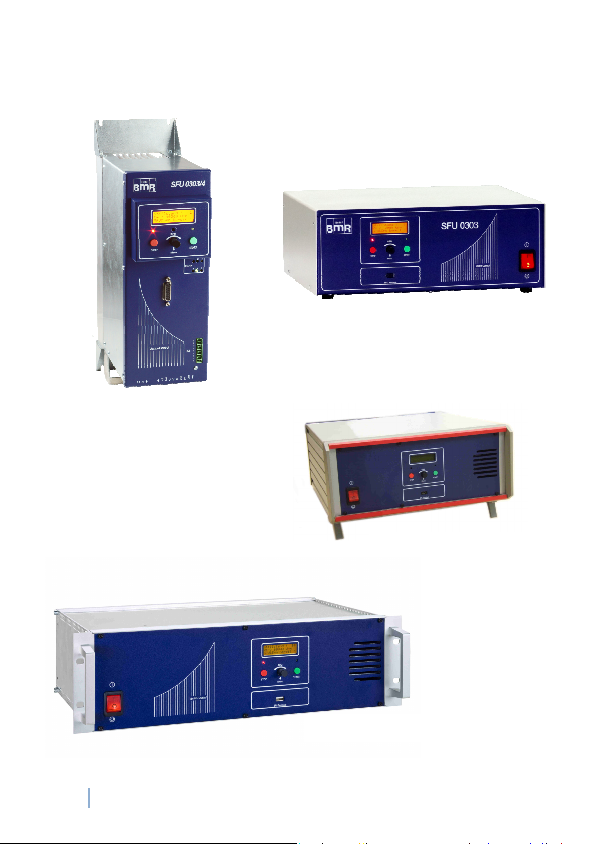
7. Functions, Commissioning, Ope ation
7.1 F ont panel SSE, Desktop and 19" Ve sion
f ont panel SSE
f ont
panel
Desktop
63TE
f ont panel Desktop
f ont panel 19" ve sion

…when it comes to quality! BMR GmbH
17
7.2 Spindle Cha acte istics and Sta ting the Conve te
Spindle Cha acte istics
All converters of BMR need an information about the basic data of the spindle, such as maximum
voltage, current, rotational speed, and many more. These are stored in so called "spindle
characteristics". A BMR spindle characteristic has 16 setpoints within the range of the rotational
speed. At every point data of voltage, current, load scaling, acceleration and deceleration ramp and
many more data can be defined and this for idle load as well as for full load. And there are in total 16
places for different characteristics. The spindle characteristics are the key for any spindle and give a
possibility to control the running behavior at every load condition.
In advance of start of a spindle first, it has to be ensured, that the proper characteristic is selected and
activated. This is generally the case if the device is delivered together with a spindle and the required
setup is done. If the converter and spindle are delivered separately, the proper spindle characteristic
has to be loaded into the converter first. This can be achieved with the free setup software SFU-
Terminal, easily.
In case of being unsure, characteristics for most common spindles are available at BMR.
The spindle characteristics can be defined either in the project file ( * .ps5 ) or via a setting in the
operating panel (-> 7.4 Setup ) . Furthermore, with the activation of the remote control interface is X4
( 6.3 / 6.6 ) a control via the digital inputs Bit1 ... Bit4 to X4 possible. The setting in the project file or
via the operator panel is then ineffective, however.
Spindle characteristics are created by BMR and can be loaded and managed using the SFU - Terminal .
Sta t and Stop
There are several possibilities for starting and stopping a spindle, due to many different requirements,
as follows below:
Generally, a STOP can be triggered by the source of START, only, with the exception of an Emergency
Stop, activated power stage pulse locking or any other safety function.
Start button at operating panel, Rotational speed with encoder potentiometer
Serial control with commands via RS232 / USB interface
Digital input in combination with an activated analogue input for control of rotational speed. In case of
not being activated, the rotational speed is setup with encoder potentiometer at the operating panel
or via serial commands.
Status display
The current status of the converter is displayed on the status LED display and with mounted operating
panel the status is displayed in plaintext on the LCD-display, additionally.

18
SFU 0303 F equency Conve te
7.3 Status LED Display at SSE
Picure 14
Typical displays. Other combinations are possible due to status.
Ready + Standstill
Converter and Spindle ready
Converter OK,
Spindel running
Spindle running Excess
temperature at Converter
Converter ready
Spindle running,
Excess temperature at Spindle
A Start is possible, if the display shows "Ready+Standstill - Converter and Spindle ready".
There are different means for solving errors which are listed in Chap "Troubleshooting"
The most probable reason for problems is a not properly wired input for "Emergency Stop"
or "Intermediate Lock". In this case it is recommended, to check the setting in the menu "Digital
Inputs" in SFU-Terminal
Converter OK,
and Spindle is running
Overload
Emergency Stop
and/or Locked
Power Stage Pulse Lock active
Ground fault
1 2 3
4 5 6
Emergency Stop
Power Stage Pulse
Locking
SFU Ready
Run / SFU is running
Overload
Excess temperature spindle
Spindle not ready
Table of contents
Other BMR Media Converter manuals


Popular Media Converter manuals by other brands

Cirrus Logic
Cirrus Logic CS4399 manual

Kiloview
Kiloview DC220 quick start guide

Iseevy
Iseevy ISV-HCD5 user manual

Advantech Wireless
Advantech Wireless SSPBM-K150-BRE Installation and operating manual

Renu Electronics
Renu Electronics GWY- MPI instruction sheet

GRASS VALLEY
GRASS VALLEY Kudos Pro-IP-LC Series user manual

AMG
AMG AMG210M Series Installation Manual - Hardware

Axis
Axis AXIS Q7406 installation guide

Miele
Miele Segosoft SegoSerial Industrial Grade... Installation and administration

Dynalink
Dynalink A 3106 operating instructions

Musical Fidelity
Musical Fidelity V-LINK II instructions

JK Audio
JK Audio Four IFB user guide


