BMS Timemachine TM01 User manual

www.bmc-racing.com
timemachine
OWNERS MANUAL
ENGLISH

timemachine
OWNERS MANUAL
Owners Manual –english

Introduction
Positioning
How to measure your position
Determine the right frame size and configuration
Seat post hardware position
Frameset overview
Building a timemachine
Recommended tooling
Recommended procedure
Frame preparation
Di2 specific parts
Parts to check
Brakesets
Assembling the brake arms
Brake cable routing (front)
Installing the pipe on front brake
Brake cable routing (rear)
Cable tension (front brake)
Cable tension (rear brake)
Brake pads setting
Di2 shifting
Cable routing
Handlebar specifics
Mechanical shifting
Cable routing
Hingefork and headset
Headset parts overview
Assembly procedure
P2p stem system
Headset parts overview
Assembly procedure
P2p seatpost
Seat post clamp
Service instructions
Washing your bike
Troubleshooting
CONTENTS
Owners Manual
3
5
5
8
10
11
13
13
14
14
14
15
16
16
18
19
19
21
22
22
24
25
27
27
27
29
29
29
31
31
32
33
33
35
35
37
Contents

BMC timemachine frame and components are designed as a system to provide a very high level of aerodynamics and riding
performance. Adjustability was not in any way compromised and the timemachine offers the highest adjustment possibility ever built
into a fully integrated time trial bicycle.
Adjustability being a key part of the system’s performance, it is necessary to understand that most components of the frameset
have been designed specifically for timemachine and their function may slightly differ from your traditionnal road bike “off the shelf”
components.
BMC timemachine uses all the latest and most high-end technologies that can be found in bicycle manufacturing, including sharp edged
and thin-walled carbon fiber composite construction, which should be treated with delicacy from the end user to prevent permanent
and sometimes invisible damage.
For the reasons mentioned above, we ask you to carefully follow the instructions provided in this manual.
Incorrect mechanical operation on your bicycle could lead to serious damage, which could cause you to fall and lead to injury
or death.
If you do not have the appropriate tools or experience to execute the following instructions, or if you need further information,
please contact your official BMC dealer for service of your bicycle.
Introduction
Introduction
2 | 3
Introduction

A bicycle rider will only perform at his best if he is correctly positioned on his bike, especially for time trial and triathlon competitions.
The following instructions are simple guidelines to help you decide which size and which stem configuration to choose in order to reach
a given handlebar position. We do not in any way provide you with a fitting tool, those instructions can only help you once your position
is defined. If you wish to change the position from your previous bike or if the timemachine will be your first time trial bike, we highly
recommend you to visit a professional fitting expert.
Many different handlebar types and shapes are available on the market and it is not possible for BMC to guarantee accurate positioning
for all of them. The handlebars provided with the TM01 complete bikes were carefully selected to offer the highest adjustment possibilities
in a light, reliable and user-friendly package. Therefore we suggest you should use the original timemachine handlebars and carefully
follow the instructions.
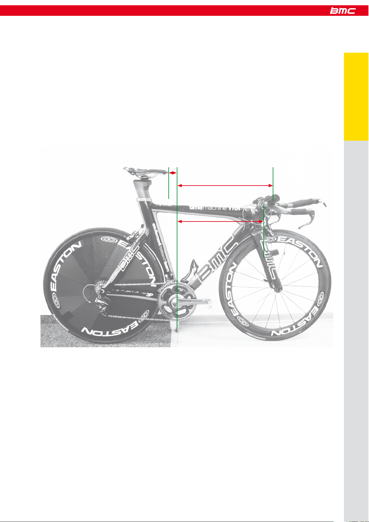
Positioning
In best case you already have a bike adjusted to your desired position. If there is any doubt for you regarding which position you should
use, we highly recommend you to visit a professional fitting expert, who will be able to give you the required data.
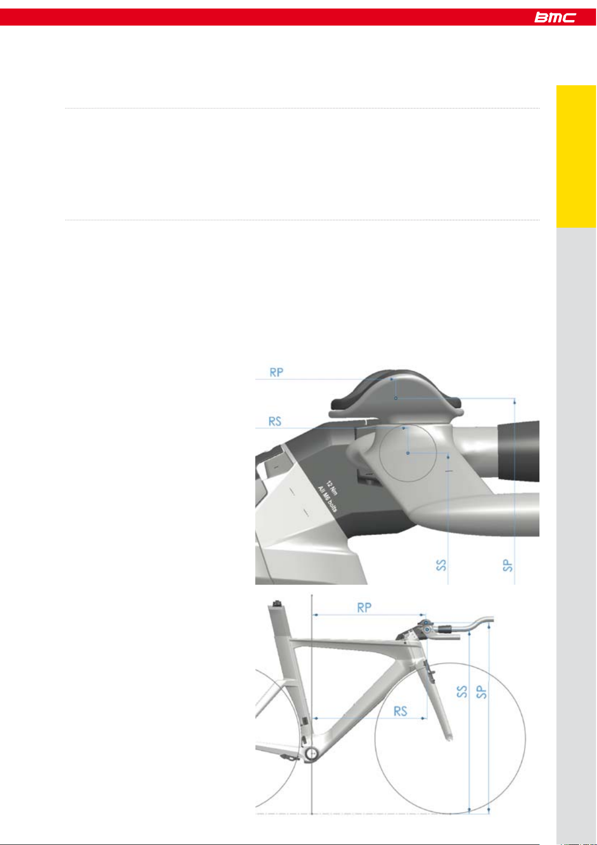
To determine the right frame size, stem and seatpost hardware position, the following measurements are required:
- stack (SP) and reach (RP) to the pads of your bars (Figure 1 and 2)
- stack (SS) and reach (RS) to the center of the handlebar clamp of the stem (Figure 1 and 2)
How to measure your position
Figure 1
Figure 2
4 | 5
Positioning
Positioning

- stack (SB) and reach (RB) of your bars (Figure 3a and b)
Figure 4
Figure 3a
- seatback to the saddle tip, valid for all Arione and SLR saddles (SB)
- vertical seat height to the top of the saddle (VSH)
- BB height (BBH)
Figure 3b
Positioning

To take those measurements, the easiest way is to place your bike on a even, horizontal ground and lean it against a vertical edge (for
example a corner of a wall, a pole or a door case) and align it so the edge is centered on the bottom bracket axle.
Then follow this procedure (picture):
- Measure the vertical distance between the BB axle center and the ground (BBH).
- Measure the vertical distance between the ground and the top of the saddle (VSH).
- Measure the vertical distance from the ground to the middle and upper surface of the bar pads (SP).
- Measure the vertical distance from the ground to the center of the handlebar clamp (SS).
- Measure the horizontal distance from the edge your bike is leaning against to the center of the pads (RP).
- Measure the horizontal distance from the edge to the center of the handlebar clamp (RS).
- Measure the horizontal distance from the edge to the tip of your saddle (SSB) (Figure 5).
Figure 5
Example: how to measure the reach on your old bike
6 | 7
Positioning
RP
RS
SSB
Positioning

For frame size and stem configuration, it is important to calculate the SSnew and RSnew values that your timemachine will be to.
All dimensions are in millimeters!
Determine the right frame size and stem configuration
You intend to use: Please calculate:
Your old bars on new TM SSnew = SS - BBH
RSnew = RS
Standard TM bars (Profile) SSnew = SP - 60 - BBH
RSnew = SP + 20
Any other new bars SSnew = SP - SB - BBH
RSnew = RP + RB
Once you know your SSnew and RSnew:
Place the SS and RS values in the chart (Figure 6) onto the horizontal and vertical.
The chart shows the various handlebar center positions you can achieve on TM01.
Check which point comes closest to the position you have calculated.
The color shows the frame size, the number is a reference to the stem configuration. All the stem configuration are listed in the second
chart (Figure 7).
The Profile aero bars specified on the complete bike offer additional pad adjustment, so you will be able to reach your desired position
even if the position you choose to build is some millimeters away from the calculated values.
You can use the tool on our homepage.
Measure SB and RB on your new bars
Measure SP, RP and BBH on your old bike
Stack and Reach BB to Handlebar Clamp
Figure 6
SSnew
RSnew
Positioning

Figure 7
stem configuration
123 4
5 6 7 8
910 11 12
13
17
21
25
29
14
18
15 16
19 20
24
2322
26
30
27
31
28
32
8 | 9
Positioning
Positioning

To determine the right position of the seatpost hardware, you need to know SB and SH.
- You can measure SB on your previous bike
- Use SH = VSH - BBH
Then place the SSB and SH values in the chart below. The point thus created will fall into a colored zone. The color code will then
indicate where to mount the saddle hardware.
Seat post hardware position
SSB (saddle seat back)
Color code
Positioning
SH (vertical seat
height from BB))

Frameset overview
10 | 11
Frameset
Page 33
Page 31
Page 29
Page 15
Page 17 Page 16
Frameset overview

A timemachine frameset or complete bike includes proprietary components such as brakes, fork, headset, stem, seat post … For each
of those components, you will find part numbers, service and assembly instructions detailed in the next chapters of this manual.
Building a timemachine
Before you start assembling, make sure you are equipped with the following tools:
- Allen keys: 2mm, 2.5mm, 3mm, 4mm, 5mm
- Ratchet wrench with 8mm allen socket
- Flat wrench 9mm, 13mm
- Red Loctite 271
- Grease gun or grease brush
- Wire cutter pliers
- Long reach pliers
- A black marker pen
- Electrical tape
- 1 extra shifting cable
- Heat gun or hair dryer
- Torque wrench with 4, 5 and 8mm allen heads sockets
- Carbon friction paste
- Bike stand with fixation for frame and fork
Recommended tooling
12 | 13
Building
Building a timemachine

1Frame preparation Refer to page 14, install rear wheel adjusters
2Mount the brake arms in frame Refer to page 15
3Rear brake cable routing Refer to page 19
4Shifting cable routing Non Di2: Refer to page 27
5Shifting cable routing Di2: Refer to page 25
6Derailleur, front and rear Refer to manufacturers instructions
7Fork and headset Refer to page 29
8Stem Refer to page 31
9Handlebars Di2: Refer to page 27
10 Front brake cable routing Refer to page 18
11 Install the pipes on brake cables Refer to pages 19
12 Brake cable tension front and rear Refer to pages 21 and 22
13 Mount wheels and brake pads Refer to page 22
14 Bolt on stem cover For TM01: Refer to page 36
15 Install top tube cable guide Only for TM02
16 Seat post installation Refer to page 33
17 Crankset Mount the crank set once the rear brake is properly set
18 Chain Refer to manufacturers instructions
19 Gears Adjust the shifting, refer to manufacturers instructions
20 Bar tape Wrap the bar tape as a final step
If you are building a timemachine frameset from scratch, the most convenient way is to follow the order and the procedure described
below. This is only the global procedure, all the seperate steps and recommendations are described one by one in the next pages of
this manual.
Please go through all the instructions before starting the assembly of the frameset.
Recommended procedure
FD cable stopper for mechanical groupset
Part N° 210995
Frame preparation
Di2 specific parts
When the frameset is built with Shimano Di2 groupset, replace the front derailleur cable stopper by the special cover
(highlighted in blue).
Cover for Di2 groupset
Part N° 210996
Building a timemachine

Before assembling the frame, it is important to check
- RD hanger bolts should be well tightened with 2mm Allen key.
- Brake bosses should be mounted and tightened with red Loctite (when new, the parts are prepared at the factory).
- Timemachine frames are equiped with wheel adjusters at the rear dropout. Use the nuts to properly align the rear wheel into the frame.
Description Part N°
1Derailleur hanger & bolts 210544
2Axle adjuster 210545
- The nut should be placed so that the O-ring seal is facing towards the hub.
1
2
15 |16
14 | 15
Building
Building a timemachine

Brakesets
The timemachine is equiped with custom brakes which are only available for this specific model from BMC. The function and installation
are different from what you may be used to on less integrated road bikes.
We ask you to carefully read and follow the instructions in order to avoid misuse.
Assembling the brake arms
Description Part N°
Brake kit (all parts) 210534
1Brake arms (front)
2Springs
3Brake bosses 210541
4 Brake bolts
5Brake stoppers 210540
6Brake cover 210525
7Pipe 210538
8Pipe holder 210539
- Grease should be applied on the brake bosses and springs, and red Loctite on the brake arm bolts.
Longest extension of the spring
should point out of the brake
arm.
2
3
1
1
5
7
6
2
4
3
8
Building a timemachine

- The arms should be tightened in “open position”, and then place the stoppers to maintain them in position.
Torque 4.5 Nm
- Each brake arm should operate smoothly from the stoppers position.
- Front and rear brake arms have a different shape, but function and installation are the same.
Description Part N°
Rear brake set 210535
1Springs
2Brake arms
3 Brake bolts
4Brake stoppers 210540
5Pipe 210538
6Pipe holder 210539
4 5
6
7
16 | 17
Building
1
2
34
65
Building a timemachine

Brake cable routing (front)
- Run the brake cable in the bars (1), and then inside the fork (2), either on left or right hand side depending on how you run your brakes.
- Use the cable as guide to slide in the housing (3). Pull on the cable until the housing sits well in the brake lever (4).
- Mark where the housing exits the fork (5), then take it out of the fork and cut it shorter 15mm from the mark (6).
Reinstall the housing into the fork, using the cable as guide.
To handlebars
1 2
3 4
56
Building a timemachine

Installing the pipe on front brake
- Always run the housing of the pipe onto the cable first (7), then run the cable into the metallic pipe (8). Pull the cable until the
housing sits well inside the pipe (9).
- Install the pipe holder while running the brake cable through the brake arm.
Brake cable routing (rear)
- Run the rear brake cable inside the bars (1) and then the frame, entering the top tube with the cut end of the cable (2).
98
7
10
1
2
18 | 19
Building
Building a timemachine

- Installing the pipe: Always run the housing of the pipe onto the cable first (6), then run the cable into the metallic pipe (7). Pull the
cable until the housing sits well inside the pipe.
- Install the pipe holder while running the brake cable through the brake arm (8).
- Use the cable as guide to slide in the cable housing (3).
- Remove the cable and cut the housing at the exit of the frame, below the BB (5).
3 4
5
6
7
8
Building a timemachine

- When you clamp the cable (2.5mm Allen), maintain the brake arms against the stoppers, and apply tension to the brake cable (1). Once
the cable is tight, check the function of the brake lever (2). There should not be play in the lever and the brake arms should come
back all the way to the stoppers. Repeat operation if needed.
- Cut the cable against the brake arm by removing the brake stopper (3).
- Bolt on the brake cover (only the front brake has a cover).
Cable tension (front brake)
It is important to understand that cable tension is independent from the position of the brakes. It means you cannot adjust the brake pad
reach by adjusting cable tension. The reach of the pads is adjusted directly on the pads with spacers.
12
34
5
20 | 21
Building
Building a timemachine
Table of contents
Languages:
Other BMS Bicycle manuals