BMS GRIZZLY-2 User manual

OPERATING INSTRUCTIONS OF GRIZZLY-2
Page 1
OPERATING INSTRUCTIONS OF
GRIZZLY

OPERATING INSTRUCTIONS OF GRIZZLY-2
Page 2
Contents
Introduction
Safe working
Extent of delivery
Technical Characteristics
Assembly
Product design and O erating
Maintenance
Re airs
Symbols
Guarantee
INTRODUCTION
The resent instruction a lies to the biomechanical stimulator „Grizzly-2“ with the electric
lift (hereinafter referred to as „stimulator“, „device“, „machine“), intended for im lementation
of stimulation for leg, arm, back and abdominal muscles on ur ose to im rove circulation of
the blood, stimulation of exchange rocesses, mobility-develo ment of joints and to im rove
hysical training.
Observe the safety warnings in this documentation and on the roduct.
It is referably to use stimulator under control of a qualified attendant, owning the methods of
biomechanical stimulation. Stimulator is designed for healthy eo le, who don’t have contra-
indications regarding manual and vibrating massage.
We advise you to consult your doctor before using of stimulation.
SAFE WORKING
It’s forbidden for children to use the stimulator. Don’t allow to the children to
lay with device. Children and ersons with mental or hysical disabilities may
use stimulator only under control of a qualified attendant.
Before using the equi ment, read and kee the following advice.
Observe the reventive regulations of your rofessional association and
the safety rovisions a licable in your country, in order to rotect
yourself and others from ossible injury.
Protect the equi ment against heat, rain or humidity. Don’t s ray the
machine with water! If the device is brought from a cold into a warm
lace, refrain from using it for about 2 hours to ado t the tem erature of
environment.
Make yourself familiar with the equi ment before using it.
Kee children away from machine.
Be attentive and careful during utilization.
Never leave the switched equi ment unattended.
Switch off the machine, disconnect the main lug from the socket and
draw the lift down to the lower osition when:
- carrying out for service or re air works
- leaving the machine unattended (even during short interru tions)
- the machine will be trans orted
Pay attention to stability of the device, es ecially by the u er osition of
the lift
Before using check the machine for ossible damage and make sure that
all the cables are connected correctly.
Never use any defective connection cable.
Prevent jam of the cables, es ecially by moving of the lift

OPERATING INSTRUCTIONS OF GRIZZLY-2
Page 3
Never overload the machine. Don’t load machine before you start it.
Don’t cover control anel or stimulator block. Don’t cover the ventilation
o enings of the control anel.
The electrical connection, re air or service of the equi ment must be
carried out by the manufacturer or by technically qualified ersons.
Use only original s are arts.
Don’t load the stimulator before you start it!
Don’t load the stimulator with more than 100 kg. Don’t stay or sit on
the stimulator. The body must have one more fulcrum besides vibratod
and handles of vibratod.
EXTENT OF DELIVERY
After un acking, check the content of the box:
- Lift with electric motor and stimulator block - 1
- Wheels for lift - 4
- Control anel - 1
- Power cord - 1
Check for ossible trans ort damage and re ort to the trans ort com any. Re ort any damage
or missing art to your su lier.
TECHNICAL CHARACTERISTCS
- Am litude of the vibration of the vibratod is 4 ± 0,5 mm.
- Frequency range of vibration is from 15 u to 37 Hz with ste s of 1 Hz.
- Procedure duration range is from 1 u to 30 minutes, with ste s of 1 minute and 3
minutes ause.
- Rating loading weight on the vibratod is 100 kg.
- Time of continuous o eration of the stimulator should not exceed 6 hours.
- The control anel and the motor of the lift are connected to an electricity network with
voltage 220-230V ± 10% and frequency 50 ± 1 Hz.
- Consumed ower doesn’t exceed 360 W.
- Sound ower level – no more than 55 dB.
- Stimulator is intended for o eration in a range of tem eratures from 10 Cº u to 35 Cº
and with relative humidity u to 80%.
- Electrical safety of the stimulator belongs to class I (Ty e B).
ASSEMBLY
Un ack the device, take it out from the box (The stimulator is delivered assembled on
the lift!) and ut it down carefully to the side. ATTENTION! The device is heavy. It
has to be taken out by at least two ersons.
Unscrew 4 screw-bolts M4 from the base of the lift.
Take out 4 black lugs from the i es of the base of the lift.
Take the wheel, insert its screw-bolt into o ening on the base of the lift and inside of
the i e turn tight screw-nut with washer. In the same way fix all four wheels.
Put 4 black lugs into the i es of the base of the lift and turn tight 4 screw-bolts M4.
Put the device on the wheels in a convenient flat lace and on the rubber rug to
revent movement of the device during work. Fix every wheel with the sto er.
Connect the cable with 4 contacts lug to socket „A“ on the back side of the control
anel. Connect the cable with 7 contacts to socket „B“ on the back side of the control
anel.

OPERATING INSTRUCTIONS OF GRIZZLY-2
Page 4
Connect the ower cables of the control anel and the electric motor of the lift to the
ower outlet ~ 220-230 V 50 Hz.
PRODUCT DESIGN AND OPERATING
The device consists of lift with electric motor, stimulator block and control anel.
Cont ol panel su lies necessary voltage for o erating the stimulator block and allows to
choose necessary rocedure duration and vibration frequency.
Front anel com onents:
- Power button «NETZ» turns the stimulator on and off.
- Button «EIN» – to begin a rocedure of stimulation.
- Button «AUS» – to sto a rocedure of stimulation.
- Buttons « - », « + », « F » - to adjust a necessary frequency and time of stimulation.
- Button « P » - to choose or adjust a necessary rogram.
- Dis lay reflects the current arameters:
F – frequency of stimulation, T – time of stimulation
tº
k
C – current tem erature of the control anel
tº
m
C – current tem erature of the engine of the stimulator block.
Back anel com onents:
- Two safety fuses T 3,15A for ~250 V
- Sockets „A“ and „B“ to connect the cables of the stimulator block.
- Socket for the ower cable of the control anel.
- Safety fuse T10A for second circuit ~42V.
The stimulato block consists of engine, case, crank-con-rod mechanism and vibratod. In the
stimulator block rotor revolution of the engine is transformed into reci rocating movement of
the vibratod.
The lift consists of lift constructions, electric motor and control anel. By ressing the
buttons „u “ and „down“ you can move the lift u wards and downwards. By using the handle
on the right side of the lift you can change the itch of the lift-underside with the stimulator
block. ATTENTION: During the change of the itch of the stimulator block and till you fix
the handle in the ro er o ening, you must kee reliably the underside of the lift! Before
using the device make sure, that the handle is fixed in the ro er o ening!
Ope ating
- Set the ower switch into u er osition.
- Choose the osition of the lift (height and itch)
- Using the button « F » choose frequency or time of stimulation and then by using the
buttons « - », « + » set arameters.
- Take the osition of the body.
ATTE TIO !
Don’t load the stimulator before you start it!
Don’t load the stimulator with more than 100 kg. Don’t stay or sit on the
stimulator. The body must have one more fulcrum besides vibratod and
handles of vibratod.
- Press the button « EIN » to start stimulation.
- After ex iration of defined rocedure time stimulator sto s automatically. If you want
to sto stimulator earlier ress the button « AUS ». In order to continue stimulation
ress again « EIN ».
OPE
You can also choose
a
dis lays. Press the butto
accordingly.
Working with the rogra
the number of t
he rogra
button « EIN
» to start s
MAINTENANCE
For maintenance a ly to your s
Clean the device with
medical s
REPAIRS
Re airs may be erformed only
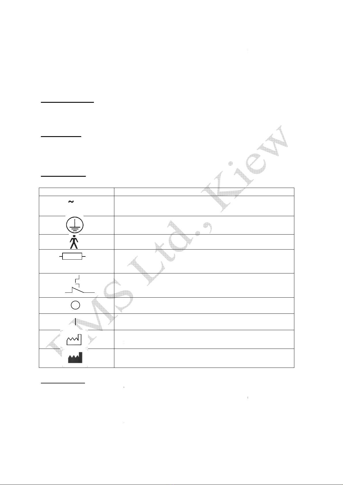
SYMBOLS
Des
alter
earth
rod
fuse
90 C
t
her
off
on
d
ate
man
GUARANTEE
This roduct is in conformity w
1:2004, ДСТУ CISPR 14-
2:2007,
Guarantee – in Kiev (UA), 24
Damage attributable to normal w
from the guarantee.
Se vice: BMS ltd
OPERATING INSTRUCTIONS OF GRIZZLY
-2
Page 5
a
rogram. Press the button « P
». The numb
e button «
F » and with buttons « - », « +
» set fr
rogram.
Press the button « P
» and with buttons «
rogram. The dis lay shows the arameter
of t
he
start stimulation
.
your su lier.
We recommend maintenance once
dical s irit or with 3% hydrogen
eroxide.
d only by qualified ersonal!
Descri tion
alternating current
earthing
roduct of ty e
В
fuse
hermal fuse
off
on
ate
of manufacture
manufacturer
ity with
EN 60335-1:2012, EN 60335-2-23:2003
,
007,
ДСТУ IEC 61000-3-2:2004, ДСТУ
EN 61000
months after dis atch date from Kiev (UA).
ormal wear and tear, overload or im ro er handling
number
of the rogram
set frequency and time
ttons «
- », « + » choose
he rogram. Press the
once in year.
,
ДСТУ CISPR 14-
00
-3-3:2004.
ndling will be excluded
Table of contents
Popular Medical Equipment manuals by other brands


Getinge
Getinge Arjohuntleigh Nimbus 3 Professional Instructions for use

Mettler Electronics
Mettler Electronics Sonicator 730 Maintenance manual

Pressalit Care
Pressalit Care R1100 Mounting instruction

Denas MS
Denas MS DENAS-T operating manual

bort medical
bort medical ActiveColor quick guide

AccuVein
AccuVein AV400 user manual


