Stack ST8956 Installation and operating instructions

Part No. ST542090-003
ST8956(W) WiFi Recorder
Users Guide Addendum


Preface
ST8956(W) WiFi Recorder Users Guide Addendum i
Preface
Congratulations
Congratulations on choosing the Stack ST8956(W) WiFi
Recorder. This system will give you a wealth of information to
enable you to obtain the maximum performance from your
vehicle.
Purpose of this manual
This addendum will help you install and use the Stack
ST8956(W) WiFi Recorder. It assumes that you have already
read the ST8956 Multi-Function Recorder User Guide.
Related Products From Stack
If you need information about other Stack motor sport products,
these can be obtained from Stack or from your local Stack
dealer. Products available from Stack include:
•Intelligent Tachometers
•Auxiliary Gauges
•Analogue and Digital Sensors
•Data Logging Systems
•Display and Logging Systems
•Radio Telemetry Systems
•Display and Analysis Software
•Video Overlay Systems
•Solid-state Video Recorders
•Tyre Pressure Monitoring Systems
Stack ® is a registered trademark of Stack Limited.
Information in this publication is subject to change without notice and does not
represent a commitment on the part of Stack Limited. No responsibility is
accepted for error or omission.
Copyright © 2009 Stack Limited

Contents
ii ST8956(W) WiFi Recorder Users Guide Addendum
Contents
Chapter 1. Introducing the WiFi Recorder 1
How to use this Manual 1
Chapter 2. Getting Started 2
The WiFi Recorder Module 4
Connecting the Components 4
Chapter 3. Installing the WiFi Recorder 6
Fitting the WiFi Recorder Module 6
WiFi Antenna Installation 6
WiFi Antenna Safe Operating Distance 9
Chapter 4. Using the WiFi Recorder 10
Configuring the system 10
DataPro to WiFi Connection 10
DataPro Functions Available via WiFi 11
DataPro Functions Not Available via WiFi 12
Internal Battery Management 12
Chapter 5. System Specifications 13
Index 14

Chapter 1. Introducing the WiFi Recorder
ST8956(W) WiFi Recorder Users Guide Addendum 1
Chapter 1. Introducing the WiFi Recorder
The Stack ST8956(W) WiFi Recorder (MFRW) can monitor a
range of values, known as performance parameters, needed for
effective car and driver management in most competitive
situations.
The system consists of a ten-input sensor module with a built-in
32 megabyte data recorder.
All of the sensors may be recorded at rates up to 200 samples
per second (200 Hz). Data recording can be configured to start
when a parameter, eg, Engine Speed, rises above a preset value.
The recorder can hold thirty Runs and those runs can be
downloaded to your PC using the Stack DataPro software (see
separate Users Guide).
The MFR(W) can be used to drive a configurable remote
Display Module (ST8995-2) in real-time.
ST8956(W) WiFi Recorder can record up to 45 channels across
the Stack CAN network as a whole, with a network capacity of
up to 4000 sps.
All the features of the ST8956 Multi-Function Recorder operate
as usual. The WiFi option also allows the convenience of
downloading data without physically connecting to the on-car
system.
How to use this Manual
Stack recommends that you unpack and connect the components
in the system before you install it in your vehicle. This will
enable you to familiarise yourself with operating the system and
configuring it for the vehicle in which you intend to install it.
!
This manual does not attempt to explain how to interpret or use
the information from the ST8956(W) WiFi Recorder as this is
very specific to the type of vehicle in which it is installed and the
type of competition in which that vehicle is engaged.

Chapter 2. Getting Started
2 ST8956(W) WiFi Recorder Users Guide Addendum
Chapter 2. Getting Started
This chapter guides you through the initial unpacking and
setting-up of the equipment for pre-installation checks and
familiarisation with its operation.
Standard WiFi Recorder Items
The ST8956(W) WiFi Recorder is supplied with the following
standard components:
Quantity Description
1 WiFi Recorder Module (ST8956(W))
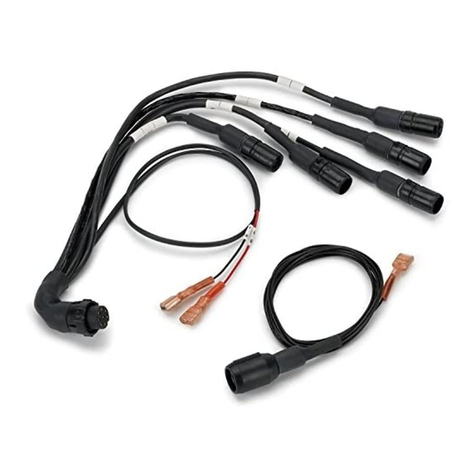
1 Sensor Harness (ST875-202)
1 ECU Engine Speed Extender (ST918024-101)
1 Network Starter Harness (ST877)
1 Stand-alone Power Lead (ST918078)
1 CAN-USB Network Interface (ST8990)
1 Recording Switch (ST517)
3 Internal G sensors
1 Bulkhead mount WiFi antenna (ST900127)
1 ST8956 MFR User Guide (ST542093)
1 DataPro WiFi Guide (ST542100)
1 DataPro Software (ST920033)
1 DataPro Quick-start Guide (ST542095)
1 Designer Quick-start Guide (ST542068)
Optional Items
Quantity Description
1 Multi-Stage Gear Shift Warning Light (ST539)
or Single Gear Shift Warning Light (ST534 or ST537)
and (ST918081) adapter cable
1 Infra-red Lap Timing Kit (ST546)
1 ST8995-2 Display Module including:-
1 Display Harness Extender (ST918094)
1 Alarm Light (ST536)
2 Peak & Lap Switches (ST510)
1 CAN ECU Interface Option (ST8996)
Various Sensors to suit your needs

Chapter 2. Getting Started
ST8956(W) WiFi Recorder Users Guide Addendum 3
Various Harness Extenders to suit those sensors

Chapter 2. Getting Started
4 ST8956(W) WiFi Recorder Users Guide Addendum
The WiFi Recorder Module
The WiFi Recorder Module consists of a compact cast
aluminium module. That module is connected to up to ten
external sensors by a wiring harness with a 19-way military
connector. A second wiring harness with a 4-way military
connector is used to connect power to the module and for
downloading data to a PC.
A third connector allows a WiFi Antenna to be connected.
Connecting the Components
Refer to the diagram below which shows the wiring for the WiFi
Recorder:-
PA1 Engine speed
PA2
PA3
PA4
A5
A6
A7
A8
A9
A10 If no display
Pulse or
Analogue
Sensors
Download
connector
to PC
Optional
CAN ECU
SL Shift light
S1 Peak switch
LAP Lap receiver
S2 Recording or
Layer switch
AL Recording or
Alarm light
3 x Internal
G sensors
Optional ST8995-2 Display
B+
B-
S3 Reset switch
Analogue
or
Network
DSP
1. Connect the Sensor Harness to the WiFi Recorder Module.

Chapter 2. Getting Started
ST8956(W) WiFi Recorder Users Guide Addendum 5
2. Connect the three switches to the wires labelled S1, S2 and
S3. If no display, just connect S2.
3. Connect the Recording/Alarm Light to the wire labelled AL.
4. Connect the optional Multi-stage Shift Light or Single Shift
Light to the wire labelled SL.
5. Connect the optional CAN ECU adaptor harness to A5 and
A6.
6. If you have the optional ST8995-2 Display Module, connect
it to the wire labelled DSP.
!
Analogue inputs A9 and A10 MUST remain disconnected if
a Display Module is being used.
7. Connect each of the sensors that you have purchased to the
appropriate wire in the wiring harness. The first four sensor
connections (PA1 to PA4) can handle either Pulse or
Analogue (5 volt) sensors. The remaining six connections
(A5 to A10) can only handle Analogue sensors.
8. Connect the SMA Jack on the antenna cable to the socket on
WiFi Recorder.
9. Connect a 12v DC power supply to the power input cable,
eg, from a car battery. B+ is battery positive and B- is
battery negative. Protect the B+ line with a 5 amp fuse.
10. Switch on the 12v DC power supply.
You can now proceed to familiarise yourself with operating the
WiFi Recorder.

Chapter 3. Installing the WiFi Recorder
6 ST8956(W) WiFi Recorder Users Guide Addendum
Chapter 3. Installing the WiFi Recorder
This chapter guides you through installing the system in your
vehicle.
Fitting the WiFi Recorder Module
The WiFi Recorder Module should be fitted to your vehicle as
described in the ST8956 Multi-Function Recorder User Guide.
The following sections describe the extra fitting instructions for
the WiFi antenna.
WiFi Antenna Installation
Antenna mounting position
•The antenna must be mounted as high as possible on the
vehicle.
•The mounting position must give clear line of sight between
the vehicle antenna and the pit lane antenna when the
vehicle is travelling in the pit lane.
•The surface to which the antenna is attached should be flat.
A maximum contour of 12 mm (0.5”) is allowed within a
diameter of 0.2 metres (8”).
•The mounting surface should be horizontal to within
±10 degrees maximum.
•The antenna should be adjusted to keep the antenna within
±5 degrees of vertical.
•No structural material or bodywork should be higher than
25 mm (1”) within a 0.6 m (2 ft) radius of the antenna base.
•The antenna must be mounted so that the connecting cable
to the WiFi Recorder is 3 m (10 ft) or less. Do not extend
the cable.
•The connecting cable to the WiFi Recorder must be kept
away from water ingress.
•Minimum distances to any other radio or telemetry antenna
must be greater than 0.5 m (18”).

Chapter 3. Installing the WiFi Recorder
ST8956(W) WiFi Recorder Users Guide Addendum 7
Antenna Fixing Instructions.
The antenna mount is suited for panel or roof mounting. The
antenna requires a minimum 90 mm (3.5”) diameter metal
ground plane under the antenna. If the fixing panel is non-
metallic, a metal disk of the required diameter must be fitted
under the panel.
•Install the antenna mount through an 18 mm (0.71”)
diameter hole. Recommended Installation Torque 3.5 Nm
(2.6 lb/ft)
•The whip antenna should be tightened with a 9 mm fork
spanner.
•The completed antenna installation is approximately
140 mm (5.5”) high.
•The mount has a bendable section (15 degrees) to adjust the
antenna into an upright position.
The antenna cable must be routed from the antenna mount to the
WiFi Recorder as follows:
•Minimum allowed bend radius is 30 mm (1.25”).
•Take care not to over-tighten any cable ties such that they
deform (pinch) the cable.
•The cable should be secured in such a way as to stop mating
connectors from being pulled apart.
•Such that it will not be trapped or crushed by any other item
on the vehicle.
•It is essential to ensure that the WiFi Recorder and harnesses
are NOT mounted in a position close to any devices or
associated wiring similar to the following:

Chapter 3. Installing the WiFi Recorder
8 ST8956(W) WiFi Recorder Users Guide Addendum
Suggested Wiring Clearances Minimum Clearance
Ignition HT and coil leads 75 mm (3”)
Radio transmitters 50 mm (2”)
Fast switching inductive loads like
fuel injectors and hydraulic
solenoids
50 mm (2”)
Any powerful sources of heat Shield with heat-
reflective material
Mounting hole dimensions (mm) as shown:
Installation sequence (fixing into a metal panel)

Chapter 3. Installing the WiFi Recorder
ST8956(W) WiFi Recorder Users Guide Addendum 9
Fixing to a non metallic panel
Remember to place the metal ground plane disk under the panel
before commencing stage 2.
WiFi Antenna Safe Operating Distance
RF safety is always a concern when working around microwave
radiation. The FCC has set safety standards that are meant to
guard against potentially harmful RF fields. In a "controlled"
environment (where the people near the antenna know of the
hazards), the FCC limit is 5.0 mw/cm2. In an "uncontrolled"
environment (where the people near the antenna are unaware of
the hazard), the FCC limit is 1.0 mw/cm2.
!
Do NOT touch the antenna when the WiFi is operating. Based
on the FCC "uncontrolled" environment limit: ‘Keep a Minimum
safe distance of 25 mm (1”) from the antenna’.

Chapter 4. Using the WiFi Recorder
10 ST8956(W) WiFi Recorder Users Guide Addendum
Chapter 4. Using the WiFi Recorder
Configuring the system
Before using the WiFi Recorder it must be configured to work
with the sensors and optional parts you have installed. This is
performed using the DataPro Designer program in the same
manner as the ST8956 Multi-Function Recorder.
!
Configurations must only be uploaded from DataPro Designer
using the CAN-USB cabled connection. Configurations cannot
be uploaded via the WiFi Connection.
DataPro to WiFi Connection
Before communication between DataPro and the WiFi Recorder
can take place the WiFi connection must be configured on your
PC. This is described in the DataPro WiFi Guide supplied.
Once the WiFi connection has been established the WiFi
Recorder must be Authorised and then Registered in DataPro as
described in that User Guide.
!
These operations MUST be performed using the wired CAN
connection and NOT via the WiFi connection.
Finally, the Active Connection must be selected for your WiFi
Recorder. All of DataPro’s Recorder menu items will use that
Active Connection to communicate with the WiFi Recorder.
This also applies to the Calibrate, Chat and Upload items within
DataPro Designer.
!
Active Connections for WiFi Recorders which are out of range
are shown in red and cannot be selected. When a WiFi
Recorder comes into rang, its list item will change to black.

Chapter 4. Using the WiFi Recorder
ST8956(W) WiFi Recorder Users Guide Addendum 11
DataPro Functions Available via WiFi
The following WiFi functions are fully supported from
DataPro’s Recorder menu:
•Download Erase Memory
•Download Save Memory
•Erase Memory
•Recorder Status
•Start Logging
•Stop Logging
Refer to the DataPro Quick Start Guide and the DataPro User
Guide for a full description of how these functions operate.
The following extra functions for WiFi Recorders only are
available from the Wireless sub-menu:
•Power off internal battery
•Prevent connection
•Connection status log
Power-Off Internal Battery
When the module is operating from the internal battery only, use
this option to power-off the module remotely via the WiFi.
Prevent Connection
Use this option to stop any communication to the module
remotely via the WiFi.
Connection Status Log
This option will show a historical log of any connections made
to the current WiFi recorder.

Chapter 4. Using the WiFi Recorder
12 ST8956(W) WiFi Recorder Users Guide Addendum
DataPro Functions Not Available via WiFi
The following functions are not fully supported via the WiFi
connection:
•Data Monitor
•Data Monitor (Raw)
•Chat Terminal
•Network information
!
These functions only show information obtained from the WiFi
Recorder and not from any other modules connected to the
on-car network.
Internal Battery Management
The WiFi Recorder contains an internal battery pack to provide
power temporarily once the vehicle power has been removed.
This allows the module to be downloaded via the WiFi even
with power removed. The internal power will automatically turn
off under the following conditions:
Description Time to power off
Recorded data is present 5 minutes
Recorded data not present 30 seconds
Internal battery is below 9 volts Immediately
The internal battery will be recharged whenever the vehicle
power is supplied to the WiFi Recorder. However, depending
on the normal running cycle of the vehicle, it may be necessary
to fully recharge the internal battery by connecting the WiFi
Recorder to a 13 to 20 volts DC supply for more than 15 hours.

Appendix D. Service and Support
ST8956(W) WiFi Recorder Users Guide Addendum 13
Chapter 5. System Specifications
Specifications as ST8956 Multi-Function Recorder except:-
Internal battery pack
Parameter Value
Input voltage for charging 13 to 20 Volts min/max
Internal battery voltage 9.6 Volts typical
Battery capacity 0.6 Amp/Hr @ 10 to 30°C
Charging current 0.06 Amps typical
Full charge time 15 hours typical
Discharge time 3 hours typical
(dependent on WiFi activity)
WiFi
Parameter Value
Transmitted power 14 ±1 dBm
Receiver sensitivity –82 to –93 dBm,
11 Mb to 1 Mb respectively
Module connector SMA (R) Reverse SMA Jack
(fixed receptacle with pin)
Network standard 802.11B
Frequency range 2.412 to 2.484 GHz
Antenna specification
Parameter Value
Antenna type Co-linear mobile whip antenna
Frequency 2.4 GHz
Transmitted EIRP 17 dBm max, 16 dBm (25 mW) typical
Polarisation vertical Vertical
Gain 2 dB
Height 140 mm (5.5”)
Weight 34 g (1.2 oz)
Mounting hole 18 mm (0.75”)
Footprint 32 mm (1.26”)
Ground plane diameter 90 mm (3.5”) minimum
Minimum Safe working
distance 25 mm (1.0”)

Index ST8956(W) WiFi Recorder
14 ST8956(W) WiFi Recorder Users Guide Addendum
Index
configuring the system, 9
fitting WiFi recorder module, 5
installing the WiFi recorder, 5
performance parameters, 1
power supply, 4
standard components, 2
unpacking, 2
WiFi recorder module, 3
This manual suits for next models
1
Table of contents
Other Stack Measuring Instrument manuals
