Geokon 4422 User manual

Instruction Manual
Model 4422
Monument Crackmeter
No part of this instruction manual may be reproduced, by any means, without the written consent of Geokon, Inc.
The information contained herein is believed to be accurate and reliable. However, Geokon, Inc. assumes no responsibility
for errors, omissions, or misinterpretation. The information herein is subject to change without notification.
Copyright ©, 2006-2017 by Geokon, Inc.
(Doc Rev F, 11/27/17)


Warranty Statement
Geokon, Inc. warrants its products to be free of defects in materials and workmanship, under
normal use and service for a period of 13 months from date of purchase. If the unit should
malfunction, it must be returned to the factory for evaluation, freight prepaid. Upon examination
by Geokon, if the unit is found to be defective, it will be repaired or replaced at no charge.
However, the WARRANTY is VOID if the unit shows evidence of having been tampered with
or shows evidence of being damaged as a result of excessive corrosion or current, heat, moisture
or vibration, improper specification, misapplication, misuse or other operating conditions outside
of Geokon's control. Components which wear or which are damaged by misuse are not
warranted. This includes fuses and batteries.
Geokon manufactures scientific instruments whose misuse is potentially dangerous. The
instruments are intended to be installed and used only by qualified personnel. There are no
warranties except as stated herein. There are no other warranties, expressed or implied, including
but not limited to the implied warranties of merchantability and of fitness for a particular
purpose. Geokon, Inc. is not responsible for any damages or losses caused to other equipment,
whether direct, indirect, incidental, special or consequential which the purchaser may experience
as a result of the installation or use of the product. The buyer's sole remedy for any breach of this
agreement by Geokon, Inc. or any breach of any warranty by Geokon, Inc. shall not exceed the
purchase price paid by the purchaser to Geokon, Inc. for the unit or units, or equipment directly
affected by such breach. Under no circumstances will Geokon reimburse the claimant for loss
incurred in removing and/or reinstalling equipment.
Every precaution for accuracy has been taken in the preparation of manuals and/or software,
however, Geokon, Inc. neither assumes responsibility for any omissions or errors that may
appear nor assumes liability for any damages or losses that result from the use of the products in
accordance with the information contained in the manual or software.


TABLE of CONTENTS
1. INTRODUCTION...................................................................................................................................................1
2. INSTALLATION ....................................................................................................................................................1
2.1 PRELIMINARY TESTS............................................................................................................................................1
2.2 CRACKMETER INSTALLATION..............................................................................................................................2
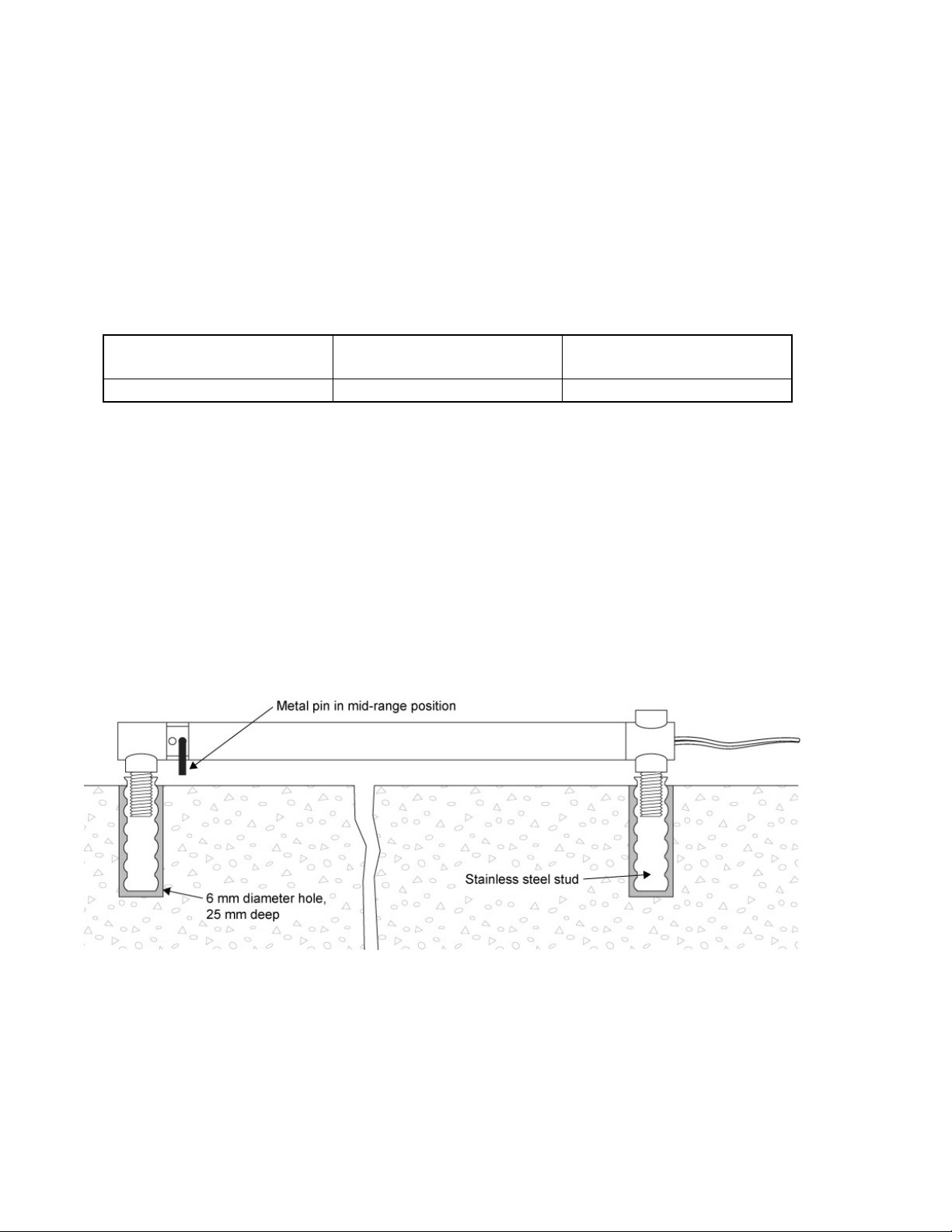
2.2.1 Drill Hole Type...........................................................................................................................................2
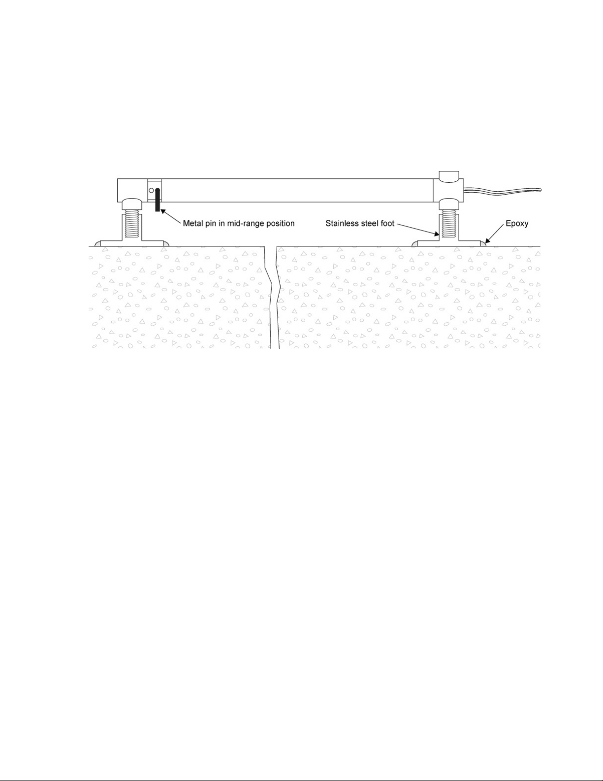
2.2.2 Surface Mounting........................................................................................................................................3
2.3 INITIAL READINGS...............................................................................................................................................3
2.4 CABLE INSTALLATION AND SPLICING ..................................................................................................................3
2.5 LIGHTNING PROTECTION .....................................................................................................................................4
3. TAKING READINGS.............................................................................................................................................5
3.1 GK-404 READOUT BOX.......................................................................................................................................5
3.1.1 Operating the GK-404 ................................................................................................................................5
3.2 GK-405 READOUT BOX.......................................................................................................................................6
3.2.1 Connecting Sensors with 10-pin Bulkhead Connectors Attached...............................................................6
3.2.2 Sensors with Bare Leads.............................................................................................................................6
3.2.3 Operating the GK-405 ................................................................................................................................6
3.3 GK-403 READOUT BOX (OBSOLETE MODEL)......................................................................................................7
3.3.1 Connecting Sensors with 10-pin Bulkhead Connectors Attached...............................................................7
3.3.2 Connecting Sensors with Bare Leads..........................................................................................................7
3.3.3 Operating the GK-403 ................................................................................................................................7
3.4 MEASURING TEMPERATURES...............................................................................................................................7
4. DATA REDUCTION ..............................................................................................................................................8
4.1 DISPLACEMENT CALCULATION............................................................................................................................8
4.2 TEMPERATURE CORRECTION...............................................................................................................................9
4.3 ENVIRONMENTAL FACTORS...............................................................................................................................10
5. TROUBLESHOOTING........................................................................................................................................12
APPENDIX A. SPECIFICATIONS.........................................................................................................................14
A.1 MODEL 4422 CRACKMETER..............................................................................................................................14
A.2 THERMISTOR.....................................................................................................................................................14
APPENDIX B. THERMISTOR TEMPERATURE DERIVATION.....................................................................15

FIGURES
FIGURE 1-MODEL 4422-1 MONUMENT CRACKMETER,GROUTABLE ANCHOR TYPE.................................................... 2
FIGURE 2-MODEL 4422-2 MONUMENT CRACKMETER,SURFACE MOUNTING TYPE..................................................... 3
FIGURE 3-LIGHTNING PROTECTION SCHEME ............................................................................................................... 4
FIGURE 4-LEMO CONNECTOR TO GK-404 ................................................................................................................... 5
FIGURE 5-LIVE READINGS –RAW READINGS............................................................................................................... 6
FIGURE 6-TYPICAL 4422 MONUMENT CRACKMETER CALIBRATION SHEET................................................................11
TABLES
TABLE 1-CRACKMETER READING RANGES.................................................................................................................. 2
TABLE 2-ENGINEERING UNITS CONVERSION FACTORS................................................................................................ 8
TABLE 3-THERMAL COEFFICIENT CALCULATION CONSTANTS .................................................................................... 9
TABLE 4-SAMPLE RESISTANCE ...................................................................................................................................13
TABLE 5-RESISTANCE WORK SHEET...........................................................................................................................13
TABLE 6-THERMISTOR RESISTANCE VERSUS TEMPERATURE......................................................................................15
EQUATIONS
EQUATION 1-DIGITS CALCULATION............................................................................................................................. 8
EQUATION 2-DEFORMATION CALCULATION................................................................................................................ 8
EQUATION 3-THERMALLY CORRECTED DEFORMATION CALCULATION....................................................................... 9
EQUATION 4-THERMAL COEFFICIENT CALCULATION .................................................................................................. 9
EQUATION 5-RESISTANCE TO TEMPERATURE .............................................................................................................15

1
1. INTRODUCTION
Geokon Model 4422 Monument Crackmeters are designed to measure movement across joints
and cracks in monuments. The small size is designed to render the crackmeter as unobtrusive as
possible. The shaft of the Monument Crackmeter has three small holes drilled in it. A metal pin
is supplied for insertion inside one of these holes. These holes and the metal pin are designed to
assist the user in selecting the range of the crackmeter so that it can be set to measure mainly
tensions, mainly compressions, or both, depending on which hole the metal pin is inserted. The
maximum range is four mm.
The instrument consists of a vibrating wire sensing element in series with a heat treated, stress
relieved spring, which is connected to the vibrating wire at one end, and to a connecting rod at
the other. As the connecting rod is pulled out from the gage body, the spring is elongated,
causing an increase in tension in the vibrating wire. The increase in tension (strain) of the wire is
directly proportional to the extension of the connecting rod. This change in strain allows the
Monument Crackmeter to measure the opening of a joint very accurately.
Monument Crackmeters are designed to be read by one of the various readout boxes available
from Geokon.
2. INSTALLATION
2.1 Preliminary Tests
Upon receipt of the instrument, the gage should be checked for proper operation (including the
thermistor). The Crackmeter normally arrives with its shaft secured at approximately 50% of its
range, by the metal pin placed inside the middle of the three holes, (see Figure 1). This holds the
instrument in tension in its midrange position. (This also helps protect it during shipping).
CAUTION! Do not rotate the shaft of the Crackmeter more than 180 degrees. This may
cause irreparable damage to the instrument. Never extend the crackmeter beyond its
working range.
Connect the gage to the readout box and take a reading. (See Section 3 for readout instructions.)
The midrange position should give a reading of about 4500 on Channel B. Gently pull on the
ends of the gage and the readings should be stable and in the range of 2000 to 7000 on Channel
B.
Checks of electrical continuity can also be made using an ohmmeter. Resistance between the
gage leads should be approximately 50 ohms, ±5 ohms. Remember to add cable resistance when
checking (22 AWG stranded copper leads are approximately 14.7Ω/1000' or 48.5Ω/km, multiply
by two for both directions). Between the green and white should be approximately 3000 ohms at
25° (see Table 6), and between any conductor and the shield should exceed two megohms.

2
2.2 Crackmeter Installation
The Monument Crackmeter is provided with threaded rods that can be either grouted in short
drill holes or epoxied to the surface. It will normally be found more convenient to fix the cable in
place before the crackmeter is attached.
The crackmeter may be installed at its midrange position by leaving the metal pin in (see Figure
1 and Figure 2 in the following subsections) or the pin may be removed, allowing the initial gage
reading to be set for the anticipated direction of movement. When setting the gage position using
a portable readout, use the reading ranges in Table 1 to determine the proper position.
Approximate Midrange
Reading
Approximate Reading to
Measure Extensions
Approximate. Reading to
Measure Compression
4500-5000
2500-3000
6500-7000
Table 1 - Crackmeter Reading Ranges
2.2.1 Drill Hole Type
For the standard range crackmeter (4 mm), drill two 9 mm (3/8”) diameter holes,
spaced 110 mm (4 3/8”) apart, to a depth of 25 mm (one inch).A drill-hole-spacer-bar
is provided to make this easier. Drill one hole then place a slightly smaller drill in the
hole and use the spacer bar to locate the second hole.
Screw the two stainless steel studs onto the threaded rods, fill the drill holes with epoxy
or quick setting cement, and push the studs into the grout or epoxy with the metal pin
holding the crackmeter at the midrange position still in place. When the grout or epoxy
has hardened then the metal pin can be removed.
Figure 1 - Model 4422-1 Monument Crackmeter, Groutable Anchor Type

3
2.2.2 Surface Mounting
For surface mounting two stainless steel feet are supplied that can be screwed on to the
threaded rods. Prepare some quick setting epoxy and apply to both the surface of the
monument and to the surface of the stainless steel feet. With the metal pin holding the
crackmeter in its midrange position still in place, press the feet down on to the monument
surface and hold in place until the epoxy sets up. Remove the metal pin.
Figure 2 - Model 4422-2 Monument Crackmeter, Surface Mounting Type
2.3 Initial Readings
Initial readings must be taken and carefully recorded along with the temperature at the time of
installation. These readings serve as a reference for subsequent deformation calculations.
2.4 Cable Installation and Splicing
The cable should be routed to minimize the possibility of damage due to moving equipment,
debris or other causes. The cable can be protected by the use of flexible conduit, which can be
supplied by Geokon.
Terminal boxes with sealed cable entries are available from Geokon for all types of applications.
These allow many gages to be terminated at one location with complete protection of the lead
wires. The interior panel of the terminal box can have built-in jacks or a single connection with a
rotary position selector switch. Contact Geokon for specific application information.
Because the vibrating wire output signal is a frequency rather than a current or voltage,
variations in cable resistance have little effect on gage readings; therefore, splicing of cables has
no ill effects, and in some cases may in fact be beneficial. The cable used for making splices
should be a high quality twisted pair type, with 100% shielding and an integral shield drain wire.
When splicing, it is very important that the shield drain wires be spliced together. Always
maintain polarity by connecting color to color.

4
Splice kits recommended by Geokon incorporate casts, which are placed around the splice and
are then filled with epoxy to waterproof the connections. When properly made, this type of splice
is equal or superior to the cable itself in strength and electrical properties. Contact Geokon for
splicing materials and additional cable splicing instructions.
Cables may be terminated by stripping and tinning the individual conductors and then connecting
them to the patch cord of a readout box. Alternatively, a connector may be used which will plug
directly into the readout box or to a receptacle on a special patch cord.
2.5 Lightning Protection
Unlike numerous other types of instrumentation available from Geokon, monument crackmeters
do not have any integral lightning protection components, such as transorbs or plasma surge
arrestors. Usually this is not a problem, however, if the instrument cable is exposed, it may be
appropriate to install lightning protection components, as the transient could travel down the
cable to the gage and possibly destroy it.
Suggested Lightning Protection Options:
•If the instrument is connected to a terminal box or multiplexer, components such as plasma
surge arrestors (spark gaps) may be installed in the terminal box/multiplexer to provide a
measure of transient protection. Terminal boxes and multiplexers available from Geokon provide
locations for the installation of these components.
•Lighting arrestor boards and enclosures are also available from Geokon. These units install
where the instrument cable exits the structure being monitored. The enclosure has a removable
top to allow the customer to service the components or replace the board in the event that the unit
is damaged by a lightning strike. A connection is made between the enclosure and earth ground
to facilitate the passing of transients away from the displacement transducer. See Figure 3.
•Plasma surge arrestors can be epoxied into the instrument cable, close to the transducer. A
ground strap then connects the surge arrestor to an earth ground, such as a grounding stake or the
rebar itself.
Consult the factory for additional information on available lightning protection.
Figure 3 - Lightning Protection Scheme

5
3. TAKING READINGS
3.1 GK-404 Readout Box
The GK-404 is a palm sized readout box that displays the vibrating wire value, as well as the
temperature in degrees centigrade.
3.1.1 Operating the GK-404
Before use, attach the flying leads to the GK-404 by aligning the red circle on the silver
“Lemo” connector of the flying leads with the red line on the top of the GK-404 (Figure
4). Insert the Lemo connector into the GK-404 until it locks into place.
Figure 4 - Lemo Connector to GK-404
Connect each of the clips on the leads to the matching colors of the sensor conductors,
with blue representing the shield (bare).
To turn the GK-404 on, press the “ON/OFF” button on the front panel of the unit. The
initial startup screen will displayed.
After approximately one second, the GK-404 will start taking readings and display them
based on the settings of the POS and MODE buttons.
The unit display (from left to right) is as follows:
•The current Position: Set by the POS button, displayed as a letter A through F.
•The current Reading: Set by the MODE button, displayed as a numeric value
followed by the unit of measure.
•Temperature reading of the attached gage in degrees Celsius.
Use the POS button to select position Band the MODE button to select Dg (digits).
(Other functions can be selected as described in the GK-404 Manual.)
The GK-404 will continue to take measurements and display readings until the unit is
turned off, either manually, or if enabled, by the Auto-Off timer. If no reading displays or
the reading is unstable, consult Section 5 for troubleshooting suggestions.
For further information, please refer to the GK-404 manual.

6
3.2 GK-405 Readout Box
The GK-405 Vibrating Wire Readout is made up of two components: The Readout Unit,
consisting of a Windows Mobile handheld PC running the GK-405 Vibrating Wire Readout
Application; and the GK-405 Remote Module, which is housed in a weatherproof enclosure and
connects via a cable to the vibrating wire gage to be measured. The two components
communicate wirelessly using Bluetooth®, a reliable digital communications protocol. The
Readout Unit can operate from the cradle of the Remote Module, or, if more convenient, can be
removed and operated up to 20 meters from the Remote Module.
3.2.1 Connecting Sensors with 10-pin Bulkhead Connectors Attached
Align the grooves on the sensor connector (male), with the appropriate connector on the
readout (female connector labeled senor or load cell). Push the connector into place, and
then twist the outer ring of the male connector until it locks into place.
3.2.2 Sensors with Bare Leads
Attach the GK-403-2 flying leads to the bare leads of a Geokon vibrating wire sensor by
connecting each of the clips on the leads to the matching colors of the sensor conductors,
with blue representing the shield (bare).
3.2.3 Operating the GK-405
Press the button labeled “POWER ON (BLUETOOTH)”. A blue light will begin
blinking, signifying that the Remote Module is waiting to connect to the handheld unit.
Launch the GK-405 VWRA program by tapping on “Start” from the handheld PC’s main
window, then “Programs” then the GK-405 VWRA icon. After a few seconds, the blue
light on the Remote Module should stop flashing and remain lit. The Live Readings
Window will be displayed on the handheld PC. Choose display mode “B”. Figure 5
shows a typical vibrating wire output in digits and thermistor output in degrees Celsius. If
no reading displays or the reading is unstable, see Section 5 for troubleshooting
suggestions. For further information, consult the GK-405 Instruction Manual.
Figure 5 - Live Readings – Raw Readings

7
3.3 GK-403 Readout Box (Obsolete Model)
The GK-403 can store gage readings and apply calibration factors to convert readings to
engineering units. The following instructions explain taking gage measurements using Mode "B"
and "F". Consult the GK-403 Instruction Manual for additional information.
3.3.1 Connecting Sensors with 10-pin Bulkhead Connectors Attached
Align the grooves on the sensor connector (male), with the appropriate connector on the
readout (female connector labeled senor or load cell). Push the connector into place, and
then twist the outer ring of the male connector until it locks into place.
3.3.2 Connecting Sensors with Bare Leads
Attach the GK-403-2 flying leads to the bare leads of a Geokon vibrating wire sensor by
connecting each of the clips on the leads to the matching colors of the sensor conductors,
with blue representing the shield (bare).
3.3.3 Operating the GK-403
1) Turn the display selector to position "B" (or "F").
2) Turn the unit on.
3) The readout will display the vibrating wire output in digits. The last digit may change
one or two digits while reading.
4) The thermistor reading will be displayed above the gage reading in degrees
centigrade.
5) Press the "Store" button to record the value displayed.
If the no reading displays or the reading is unstable, see Section 5 for troubleshooting
suggestions.
The unit will automatically turn off after approximately two minutes to conserve power.
3.4 Measuring Temperatures
Each crackmeter is equipped with a thermistor, which gives a varying resistance output as the
temperature changes. The white and green leads of the instrument cable are normally connected
to the internal thermistor.
The GK-403, GK-404, and GK-405 readout boxes will read the thermistor and display the
temperature in degrees C.
To read temperatures using an ohmmeter: Connect an ohmmeter to the green and white
thermistor leads coming from the displacement transducer. Since the resistance changes with
temperature are large, the effect of cable resistance is usually insignificant. For long cables a
correction can be applied, equal to approximately 14.7Ωfor every 1000 ft., or 48.5Ωper km at
20 °C. Multiply these factors by two to account for both directions. Look up the temperature for
the measured resistance in Appendix B, Table 6.

8
4. DATA REDUCTION
4.1 Displacement Calculation
The basic unit utilized by Geokon for measurement and reduction of data from Vibrating Wire
Displacement Transducers is "digits". Calculation of digits is based on the following equation:
Digits =1
Period2x 10-3 or Digits=Hz2
1000
Equation 1 - Digits Calculation
To convert digits to deformation use Equation 2.
Duncorrected = (R1- R0) ×G ×F
Equation 2 - Deformation Calculation
Where;
R1is the current reading.
R0is the initial reading, usually obtained during installation (see Section 2.3).
G is the gage factor, usually millimeters or inches per digit.
(See the example calibration sheet shown in Figure 6.)
F is an optional engineering units conversion factor, see Table 2.
From→
To↓
Inches
Feet
Millimeters
Centimeters
Meters
Inches
1
12
0.03937
0.3937
39.37
Feet
0.0833
1
0.003281
0.03281
3.281
Millimeters
25.4
304.8
1
10
1000
Centimeters
2.54
30.48
0.10
1
100
Meters
0.0254
0.3048
0.001
0.01
1
Table 2 - Engineering Units Conversion Factors
For example, if the initial reading (R0) is 4000 digits, the current reading (R1) is 5000, and the
gage factor is 0.001077 mm/digit, then the deformation change is calculated as follows:
Duncorrected = (5000
−
4000)
×
0.001077 = +1.077 mm
(Note that increasing readings (digits) indicate that the crack is widening.)
To use the Polynomial Gage factors given on the Calibration Sheet: Use the value of R0and
Gage Factors A and B, with the displacement (D) set to zero, to calculate the new value of C.
Next, substitute the new value of R1, and use A, B, and the new value of C, to calculate D.

9
4.2 Temperature Correction
Because Geokon’s Vibrating Wire Displacement Transducers have a small coefficient of thermal
expansion, in many cases correction may not be necessary. However, if maximum accuracy is
desired, or the temperature changes are extreme (>10 °C), a correction may be applied based on
the following equation:
Dcorrected = ((R1- R0) ×G) + ((T1- T0) ×K)
Equation 3 - Thermally Corrected Deformation Calculation
Where;
R1is the current reading.
R0is the initial reading.
G is the linear gage factor.
T1is the current temperature.
T0is the initial temperature.
K is the thermal coefficient (see Equation 4).
The temperature coefficient of the mass or member to which the Crackmeter is attached should
also be taken into account. By correcting the transducer for temperature changes the temperature
coefficient of the mass or member may be distinguished.
Tests have determined that the thermal coefficient, K, changes with the position of the transducer
shaft. Hence, the first step in the temperature correction process is to determine the proper
thermal coefficient based on the following equation:
K = ((R1×M) +B) ×G
Equation 4 - Thermal Coefficient Calculation
Where;
R1is the current reading.
M is the multiplier from Table 3.
B is the constant from Table 3.
G is the linear gage factor from the supplied calibration sheet (Figure 6).
Model:
4422
Multiplier (M):
0.000471
Constant (B):
0.3562
Table 3 - Thermal Coefficient Calculation Constants

10
The following example shows that corrections for temperature change are usually small and can
often be ignored.
R0= 4773 digits
R1= 4589 digits
T0= 20.3 °C
T1= 32.9 °C
G = 0.001077 mm/digit
K = (((4589 ×0.00073) + 0.583) ×0.001077) = 0.00424
Dcorrected = ((R1- R0) ×C) + (((T1- T0) ×K)
Dcorrected = ((4589 - 4773) ×0.001077) + (((32.9 - 20.3) ×0.000424)
Dcorrected = (-184 ×0.001077) + 0.00534
Dcorrected = -0.198 + 0.00534
Dcorrected = -0.193 mm
4.3 Environmental Factors
Since the purpose of the crackmeter installation is to monitor site conditions, factors that may
affect these conditions should always be observed and recorded. Seemingly minor effects may
have a real influence on the behavior of the structure being monitored, and may give an early
indication of potential problems. Some of these factors include, but are not limited to, blasting,
rainfall, tidal levels, traffic, temperature and barometric changes, weather conditions, changes in
personnel, nearby construction activities, excavation and fill level sequences, seasonal changes,
etc.

11
Figure 6 - Typical 4422 Monument Crackmeter Calibration Sheet

12
5. TROUBLESHOOTING
Maintenance and troubleshooting of monument crackmeters is confined to periodic checks of
cable connections and maintenance of terminals. Once installed, the crackmeters are usually
inaccessible and remedial action is limited. Gages should not be opened in the field. Should
difficulties arise, consult the following list of problems and possible solutions. Return any faulty
gages to the factory. For additional troubleshooting and support, contact Geokon.
Symptom: Thermistor resistance is too high
It is likely that there is an open circuit. Check all connections, terminals, and plugs. If a cut is
located in the cable, splice according to instructions in Section 2.4.
Symptom: Thermistor resistance is too low
It is likely that there is a short. Check all connections, terminals, and plugs. If a short is
located in the cable, splice according to instructions in Section 2.4.
Water may have penetrated the interior of the crackmeter. There is no remedial action.
Symptom: Instrument Readings are Unstable
Is the readout box position set correctly? If using a datalogger to record readings
automatically, are the swept frequency excitation settings correct?
Is the crackmeter shaft positioned outside the specified range (either extension or retraction)
of the instrument? Note that when the transducer shaft is fully retracted with the alignment
pin inside the alignment slot the readings will likely be unstable because the vibrating wire is
under-tensioned.
Is there a source of electrical noise nearby? Likely candidates are generators, motors, arc
welding equipment, high voltage lines, etc. If possible, move the instrument cable away from
power lines and electrical equipment or install electronic filtering.
Make sure the shield drain wire is connected to ground whether using a portable readout or
datalogger. Connect the shield drain wire to the readout using the blue clip. (Green for the
GK-401.)
Does the readout work with another gage? If not, it may have a low battery or possibly be
malfunctioning.
Symptom: Instrument Fails to Read
Is the cable cut or crushed? Check the resistance of the cable by connecting an ohmmeter to
the gage leads. Table 4 shows the expected resistance for the various wire combinations;
Table 5 is provided for the user to fill in the actual resistance found. Cable resistance is
approximately 14.74Ωper 1000' of 22 AWG wire. Multiply this factor by two to account for
both directions. If the resistance is very high or infinite (megohms), the cable is probably
broken or cut. If the resistance is very low (<20Ω), the gage conductors may be shorted. If a
cut or a short is located in the cable, splice according to the instructions in Section 2.4.
Does the readout or datalogger work with another gage? If not, it may have a low battery or
possibly be malfunctioning.

13
Vibrating Wire Sensor Lead Grid - SAMPLE VALUES
Red
Black
White
Green
Shield
Red N/A
≅50Ω
infinite infinite infinite
Black
≅50Ω
N/A infinite infinite infinite
White infinite infinite N/A
3000Ω at
25°C
infinite
Green infinite infinite
3000Ω at
25°C
N/A infinite
Shield infinite infinite infinite infinite N/A
Table 4 - Sample Resistance
Vibrating Wire Sensor Lead Grid - SENSOR NAME/##
Red Black White Green Shield
Red
Black
White
Green
Shield
Table 5 - Resistance Work Sheet

14
APPENDIX A. SPECIFICATIONS
A.1 Model 4422 Crackmeter
Range:
4 mm / 0.16 inches
Resolution:¹
0.025% FSR
Linearity:
0.25% FSR
Thermal Zero Shift:²
< 0.05% FSR/°C
Stability:
< 0.2%/yr (under static conditions)
Overrange:
115% FSR
Temperature Range:
-40 to +60 °C
-40 to 120 °F
Frequency Range:
1200 - 2800 Hz
Coil Resistance:
50 Ω, ±5 Ω
Cable Type:³
Two twisted pair (four conductor) 22 AWG
Foil shield, PVC jacket, nominal OD=6.3 mm (0.250")
Cable Wiring Code:
Red and Black are the VW Sensor; White and Green the
Thermistor.
Length:(midrange,
end to end)
120 mm / 4.75 in.
Notes:
¹ Minimum; greater resolution possible depending on readout.
² Depends on application.
³ Polyurethane jacketed cable available.
A.2 Thermistor
Range: -80 to +150 °C
Accuracy: ±0.5 °C
Table of contents
Other Geokon Measuring Instrument manuals

Geokon
Geokon 4700 User manual

Geokon
Geokon 1100 User manual

Geokon
Geokon GK-604D User manual

Geokon
Geokon GK-604D User manual

Geokon
Geokon GK-404 User manual

Geokon
Geokon GK-405 User manual

Geokon
Geokon 4200ER User manual

Geokon
Geokon GK-604D User manual

Geokon
Geokon 4415 User manual

Geokon
Geokon 4500 Series User manual
Popular Measuring Instrument manuals by other brands

Laser Technology
Laser Technology TruPulse 200 user manual

Aeroflex
Aeroflex 3500A Application note

EUTECH INSTRUMENTS
EUTECH INSTRUMENTS FLUORIDE EPOXY instruction manual

PCB Piezotronics
PCB Piezotronics 356A24/NC Installation and operating manual

ADA INSTRUMENTS
ADA INSTRUMENTS ProDigit MICRO operating manual

MSA
MSA ULTIMA X5000 quick start guide