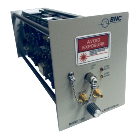
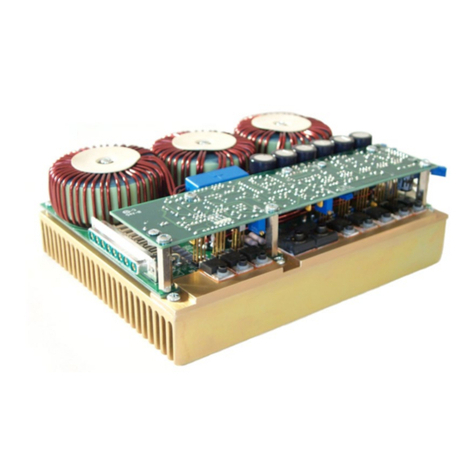
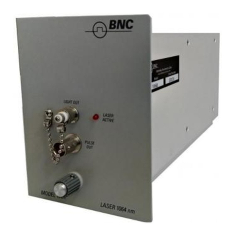
BNC 202H User manual

Electrical Module
Model 202H
2955 Kerner Blvd., Suite D San Rafael, CA 94901. Ph: 415-453-9955 Fx: 415-453-9956
www.berkeleynucleonics.com
Instruction Manual

2
WARRANTY
Berkeley Nucleonics Corporation warrants all instruments, including
component parts, to be free from defects in material and workmanship,
under normal use and service for a period of one year. If repairs are
required during the warranty period, contact the factory for component
replacement or shipping instructions. Include serial number of the
instrument. This warranty is void if the unit is repaired or altered by others
than those authorized by Berkeley Nucleonics Corporation.

3
CONTENTS
Page
SECTION 1 SPECIFICATIONS 9
Model 202H Characteristics 9
Module Status Byte Summary 11
SECTION 2 OPERATING INFORMATION 12
Description 12
General 13
Power Up 13
Module Installation 13
Warm Up Requirements 13
Protection Features 13
Short Circuit Protection 13
Over Voltage Protection 14
Over Current Protection 14
Over Temperature Protection 14
Load Requirements 14
Timing Requirements 15
Duty Factor 15
Repetition Rate 15
Pulse Spacing 16
Pulse Width 16
Performance Enhancements 16
Transition Times and Pulse Width 16
Minimum Pulse Width 17
Cables and Load Placement 17
Non 50 Ohm Loads 17
Troubleshooting 18
Front Panel Description 19
LED Indicators 19
Connectors 19
Rear Panel Description 19
Internal Controls 19
Polarity Switch 19
Mainframe Operation 20
Front Panel Programming 20
Remote Programming 22
SECTION 3 THEORY OF OPERATION 24
Output Board 25
DC Control Circuits 25
Drive Circuits 26
Floating DC - DC converter 26

4
CONTENTS
SECTION 4 MAINTENANCE AND CALIBRATION 27
Calibration 27
General 27
Equipment Required 27
Procedure 28
Power Supply Voltages 28
Output Pulse Amplitude 28
Stepcal Adjustment 28
Drive Level Adjustment 29
Minimum Pulse Width Calibration 29
SECTION 5 PARTS LIST & SCHEMATICS
Parts List
Schematics
Contact Factory for Copies

5
CONTENTS
ILLUSTRATIONS
Figure No. Page
Frontispiece Model 202H 300 V Module 8
1-1 202H Trigger and Output Pulse Timing
3-1 Module Interface Block Diagram
3-2 Output Circuit Block Diagram
TABLES
Table No. Page
1-1 202H Module Status Byte 11
2-1 Typical Duty Factor Maximums for the 202H Module 15
2-2 Typical Pulse Width Correction Factors 16
2-3 202H Module Default Settings 18
2-4 Menu Keys for the 202H Module 22
3-1 Module Memory Map 14

6
SAFETY PRECAUTIONS
The following warnings, which appear both here and in the main body of the text, are to alert the user to
potential safety hazards and to encourage safe operating practices.
.
WARNING
Hazardous shock can result from improper operation-up to 2 kW peak power may be
contacted. To avoid personal injury, use safety precautions appropriate for high voltage
sources:
Do not work alone.
Do not operate with the cover removed.
Use extreme care when handling output connections. Do not connect
or disconnect cables when high voltage is present
Be sure the ground conductor of the ac power cord connects the
instrument to a solid earth ground.
WARNING: Shock hazard. Use extreme care when handling output connections
WARNING: Do not attempt to access the polarity switch while the module is installed with
the power on.

7
SAFETY PRECAUTIONS
The following cautions, which appear here and in the main body of the text, are to prevent equipment
damage that could result from improper operation.
CAUTION: Memory 0 may consist of high voltage settings; these will go into effect every time the
instrument is turned on. To avoid accidental damage to equipment or devices left connected to the
202H, it is recommended that a low voltage setting be stored in memory 0.
CAUTION: The module must be installed with mainframe power off. A module can be damaged or
have its memory corrupted if inserted or removed from the mainframe with power on.
CAUTION: Loads connected to the 202H module must be able to dissipate up to 2 kW peak power
and 20 W average power for 300 V operation. Loads with either lower peak or average power
ratings may be damaged or destroyed.

8
300 V MODULE
MODEL 202H
(Model 202H Graphic)
The Model 202H is one in a series of output plug-in modules that provide electrical and optical pulses
when installed in the 6040 mainframe.
This particular module provides positive or negative electrical pulses with adjustable amplitude up to 30V
at rates up to 500 kHz.

9
SECTION 1
SPECIFICATIONS
MODEL 202H CHARACTERISTICS
Timing Characteristics
Rep Rate: 0 Hz - 500 kHz at 300 V (1 MHz at lower amplitudes
see Table 2-1).
Delay: 0 ns - 640 s.
Width: 15 ns - 5 ms.
Width Accuracy: Duplicates 6040 width ±2 ns. Calibrated at 300 V
(50% points). At lower amplitudes width increases
(see Table 2-2).
Duty Factor: 1% maximum at 300 V (higher duty factor at lower
amplitudes-see Table 2-1).
Pulse Separation: 200 ns minimum (between trailing and leading
edges).
Output Characteristics
PULSE OUT
Amplitude: 20 V to 300 V Peak into 50 ohms (Baseline fixed at
ground).
Polarity: Positive or negative (internally selectable).
Resolution: 2 V.
Linearity: ±1%.
Maximum Power: 18 W average, 1.8 kW peak.
Maximum Current: 6 A peak.
Transition Times: Leading edge, 5 ns (3 ns typical),
Trailing edge, 10 ns at 300 V (longer at lower
amplitudes-see Table 2-2).
Droop: 0.005%/s.
Pulse Top Aberrations: ±5% of amplitude (2% typical).
Module Delay: 55 ns typical (between mainframe PULSE OUT and
module PULSE OUT-see Figure 1-1).
Insertion Delay: 100 ns, typical (between mainframe TRIG IN and
module PULSE OUT-see Figure 1-1).
Jitter: 0125 ps rms (between mainframe PULSE OUT and
module PULSE OUT).
Connector: BNC
MODULE DISABLE: Not used.

10
SPECIFICATIONS
Modes
PULSE
Single Pulse: Conventional pulse generator with rate, delay and
width controlled by the 6040 mainframe.
Double Pulse: A pair of identical pulses of the selected width with
leading edges separated by the selected delay.
Module Memory
PERMANENT MEMORY: A ROM in a module determines the instrument's
allowable operating conditions and display units.
STORE: Ten complete instrument settings can be stored in
the module's nonvolatile RAM. The module may be
removed without loss of these settings.
RECALL: Stored settings can be manually recalled or bus
transferred to the mainframe. The setting in memory
is activated automatically upon power up or reset.
General
DIMENSIONS: 3.75" W 4.9" H 10" D (95 mm 124 mm 254
mm).
WEIGHT: 2 lbs, net (0.9 kg); 7 lbs, shipping (3.2 kg).
AMBIENT TEMPERATURE: Specifications apply: 10° - 40° C (50° - 100° F).

11
SPECIFICATIONS
MODULE STATUS BYTE SUMMARY
Table 1-1. 202H Module Status Byte
Bit
Description
7
6
5
4
3
2
1
0
Polarity
Always Zero
Always Zero
Always Zero
Always Zero
Always Zero
Locked
Overload

12
SECTION 2
OPERATING INFORMATION
DESCRIPTION
The Model 202H plug-in module provides a high voltage electrical output source for the Model 6040
Universal Pulse Generator. Output protection is provided for short circuit, over current, and over
temperature conditions.
The 202H operates only in the Pulse Mode of the 6040 mainframe, supplying flat-topped pulses of
positive or negative polarity. The 202H's Peak Level is adjustable from 20 V to 300 V and the Baseline
level is fixed at ground. The leading edge transition time is 5 ns or less (trailing edge transition time is
minimum at 300 V and increased with reduced amplitude).
Pulse width (adjustable from 15 ns to 5 ms) and delay timing are supplied by the mainframe. The trigger
source may be internal to the mainframe, external (using the 6040's TRIG IN jack) or single shot. A sync
signal (TRIG OUT) is provided in each case (see Figure 1-1). Double Pulse operation, producing both an
initial and delayed pulse out of the same jack, may be selected for any trigger choice. The mainframe
supplies +5 V pulses (from the PULSE OUT jack) approximately coincident with the module's high
voltage pulses (see Figure 1-1).
For additional details, refer to the Specification section and the 6040 manual.
WARNING
Hazardous shock can result from improper operation-up to 2 kW peak power may be contacted.
To avoid personal injury, use safety precautions appropriate for high voltage sources:
Do not work alone.
Do not operate with the cover removed.
Do not operate the module using extender cables.
Use extreme care when handling output connections. Do not
connect or disconnect cables when high voltage is present.
Be sure the ground conductor of the ac power cord connects the
instrument to a solid earth ground.

13
OPERATING INFORMATION
General
POWER UP
When power is applied to the 6040 mainframe with a 202H module installed, the instrument settings from
the module's memory 0 are activated. The mainframe automatically checks what type of plug-in module
is in place and loads the appropriate parameters. The LCD, after showing the mainframe's software
version number and performing a memory check, will display "202H Ver. x.x." where "x.x" is the version
number of the module.
Module Installation
To install the module, turn off the mainframe, then slide the module in and tighten the mount screw knob.
Warm up Requirements
The instrument should be allowed to warm up for ten minutes before high precision measurements are
made. Less output, less critical tests can be performed immediately after turn on.
PROTECTION FEATURES
The 202H module incorporates circuitry to prevent accidental damage to the module due to shorts
applied to the output, high voltage reflections, excessive current demand and over temperature
conditions.
Short Circuit Protection
If a short or near-short appears at the output while the 202H is producing a pulse, the module will
respond by rapidly turning off the pulse being generated. This protects the 202H output stage from
damage. It takes effect if the short is present when the pulse begins (even if the short is present before
the instrument is turned on) or if the short is applied after the pulse has started.
CAUTION: Memory 0 may consist of high voltage settings; these will go into effect every
time the instrument is turned on. To avoid accidental damage to equipment or devices left
connected to the 202H, it is recommended that a low voltage setting be stored in memory 0.
CAUTION: The module must be installed with mainframe power off. A module can be
damaged or have its memory corrupted if inserted or removed from the mainframe with the
power on.

14
OPERATING INFORMATION
When the protection circuit turns the pulse off, the active front panel LED (see the LED Indicators
section) flashes to alert the user to a fault condition. Additionally, the Overload bit of the Module Status
byte will go high. The output is disabled and held at zero for about four seconds before the module tries
to put out another pulse. When it does retry, the output level will be raised slowly. If a short circuit
condition is not present, pulses are produced normally. If a short is still present, the output is again
disabled, the LED starts blinking and the cycle repeats. The 202H will continue to retry every four
seconds until it detects that a short circuit condition no longer exists.
Over Voltage Protection
The energy of a high voltage pulse traveling down a length of cable can be reflected back if the
impedance terminating the cable does not match that of the cable itself (50 ohms). An unterminated
cable (open circuit) will produce a reflected wave of double the pulse amplitude. For a long cable and a
wide pulse, the energy carried back in such a reflection could potentially damage an unprotected output
stage. To prevent this, the 202H employs circuitry to clamp such reflections to a safe level. This circuitry
does not interrupt the operation of the module, and the front panel LEDs are unaffected by it.
Over Current Protection
When the specified duty factor maximum for a given pulse level is exceeded (see the Duty Factor
section), the 202H will go into a current limit state and the output will drop below its programmed value.
Using a low impedance load may have this effect as well, even when duty factor maximums have not
been exceeded. Additionally, entering a large change in the programmed level may momentarily cause a
current limit condition.
While the instrument is current limiting, the active front panel polarity LED will flash (and the Overload bit
of the Module Status byte will be set). When the cause of the current limit condition is removed, the 202H
output will slowly rise until it again produces pulses of accurate output level.
Over Temperature Protection
When the specified maximum pulse repetition rate for a given pulse level is exceeded (see the Timing
Requirements section), overheating of the output stage can result. To prevent this, the 202H
incorporates thermal protection circuitry that will slowly lower the output level when this occurs. The
active front panel polarity LED will flash (and the Overload bit of the Module Status byte will be set).
When the repetition rate or output level is reduced, the 202H will return to normal operation.
LOAD REQUIREMENTS
CAUTION: Loads connected to the 202H module must be able to dissipate up to 2 kW peak power and
20 W average power for 300 V operation. Loads with either lower peak or average power ratings may be
damaged or destroyed.

15
OPERATING INFORMATION
The 202H is designed to operate with a load impedance of 50 ohms. For operation at 300 V, the load
must be rated for 2 kW peak power and 20 W average power dissipation. (Terminators of sufficient
power rating are available from BNC.)
Note that the failure modes for loads with insufficient power ratings may vary. Some loads will arc and
behave as a short (either temporarily or permanently). Others, instead, will simply open up.
TIMING REQUIREMENTS
Duty Factor
The 202H module can operate at a maximum duty factor of 1% at 300 V. For operation at lower Peak
voltages, the duty factor may be increased. Table 2-1 shows typical maximum duty factors for various
programmed levels. If the duty factor is too high, the 202H Over Current circuitry will respond by
decreasing the pulse amplitude and flashing the active front panel LED (as described in the Over Current
Protection paragraph).
Table 2-1. Typical Duty Factor Maximums for the 202H Module
Peak Level
Maximum
Duty Factor
Maximum
Pulse Rate
Maximum Pulse Rate
For 100 ns Width
300 V
1%
500 kHz
100 kHz
250V
1.5%
650 kHz
150 kHz
200 V
2%
800 kHz
200 kHz
150 V
3%
1 MHz
300 kHz
100 V
5%
1 MHz
500 kHz
50V
10%
1 MHz
1 MHz
20V
25%
1 MHz
1 MHz
Repetition Rate
Independent of duty factor, the maximum pulse rate depends on pulse amplitude, as shown in Table 2-1.
For Single Pulse operation, this pulse rate corresponds to the external or internal trigger rate. When
Double Pulse timing is used, the maximum pulse repetition rate in the table corresponds to twice the
maximum allowable trigger rate.
When the maximum pulse rate is exceeded, the output level will drop and a front panel LED will flash (as
described in the Over Temperature Protection paragraph).

16
OPERATING INFORMATION
Duty factor constraints may additionally limit the repetition rate for a given pulse width. As an example,
the last column in Table 2-1 gives the maximum repetition rate when a 100 ns width is used (in Single
Pulse operation).
Pulse Spacing
A minimum pulse spacing of 200 ns is required between the trailing edge of a pulse and the leading edge
of the following pulse. If this minimum spacing is not met, output pulses may disappear.
Pulse Width
The maximum pulse width is limited to 5 ms at all output levels. The 202H will not allow longer width
settings to be entered.
Note that pulse top droop will become apparent for pulses wider than 200 us (over 1% droop).
PERFORMANCE ENHANCEMENTS
Transition Times and Pulse Width
While the leading edge transition time remains 5 ns or less over the entire range of amplitude levels (20
V to 300 V), the trailing edge transition time increases as the amplitude decreases. The length of the
pulse top remains constant when the amplitude is changed and as a result the actual pulse width
increases as the amplitude decreases. The programmed Width (as displayed) applies to 300 V
(measured at the 50% points). Typical trailing edge transition times and width correction factors are given
in Table 2-2.
Where a high degree of accuracy is required, pulse width should be measured at the levels being used.
To obtain pulses lower in amplitude than 300 V without increased trailing edge transition time, set the
level to 300 V and use an external attenuator. Be sure that the attenuator presents 50 ohms to the 202H
output and that the attenuator and load combination can dissipate 20 W average power and 2 kW peak
power. (A selection of high power attenuators are available from BNC.)
Table 2-2. Typical Pulse Width Correction Factors
Peak Level
Trailing Edge Transition Time
Correction Factor
(at 50% points)
300V
10 ns
-
200 V
11 ns
+ 1 ns
100 V
13 ns
+ 2ns
20 V
35 ns
+ 8ns

17
OPERATING INFORMATION
Minimum Pulse Width
Although 15 ns is specified as the minimum pulse width, the user may enter a Width parameter as low as
10 ns. This allows a narrower pulse to be produced, but amplitude and width accuracy may be affected.
The 202H specifications only apply for widths 15 ns and above.
Cables and Load Placement
The output of the 20 2H should be connected to a single 50 ohm termination via 50 ohm coaxial cable.
Coax cable with even a few ohms difference in characteristic impedance can generate reflections
observable on the waveform as aberrations.
Placing the load termination at the very end of the cable and avoiding long stubs, Y's or T's will reduce
reflections that can cause unwanted aberrations as well. Note also that excessive cable length can
adversely affect transition times.
Non 50 Ohm Loads
In some cases, the 202H can be used with other than 50 ohm loads. When doing so, the instrument will
be uncalibrated, and the specifications will not apply.
The use of a non 50 ohm load will mean an impedance mismatch or discontinuity at the load. This
mismatch will result in reflections of the output pulse as it reaches the load. As a result, the waveform will
exhibit aberrations depending on the degree of the mismatch. The time position and appearance of the
aberrations will vary with pulse width and cable length (cable transit time is approximately 1.3 ns per foot
of cable).
Resistive loads with greater than 50 ohm impedance, in addition to generating aberrations, will cause the
trailing edge transition time of the pulse to increase. The larger the load resistance, the longer the trailing
edge transition time will be. The leading edge should not be significantly affected. Another result of using
higher impedance loads is that the 202H may allow larger duty factor settings before going into an over
current state. For very high impedance loads, using a 50 ohm terminator in parallel with the load may
provide a cleaner waveform.
Resistive loads with less than 50 ohms impedance will generate aberrations and will cause an over
current state at a lower duty factor than specified for the 202H. If the resistance is small enough, the
short circuit protection may shut off the output (see the section on Short Circuit Protection).

18
OPERATING INFORMATION
Capacitive loads may be driven as well, provided a 50 ohm termination is used in parallel with the
capacitance. In most cases best results are obtained when the capacitance is located at a T (with
minimul stub length) close to the 50 ohm terminator (which should be placed at the most distant end of
the cable system). A capacitance will act as a momentary short, and will generate aberrations that
depend on the size of the capacitance. A capacitance too large will trip the short circuit protection. Rise
and fall times will be longer with a capacitive load.
TROUBLESHOOTING
Follow the procedure in the Troubleshooting section of the 6040 manual. Make sure that the module is
seated correctly in the mainframe. If the module's memory has been corrupted, a cold boot will put the
module's default settings into effect (as described in the Cold Boot section in the 6040 manual). Table 2-
3 gives the default settings for the 202H module.
Table 2-3. 202H Module Default Settings
The Quick Test procedure for the mainframe may be applied to the 202H by selecting the Pulse Mode
and following the test sequence using the module's PULSE OUT connector in place of the mainfame's
PULSE OUT.
If the output drops in level or the front panel LEDs blink, check that a 50 ohm load is being used (see
Load Requirements). Also check that duty factor and repetition rate maximums are
not being exceeded (see the Timing Requirements and Protection Features sections). For problems
relating to output pulse aberrations, refer to the section on Cables and Load Placement.
MODE: Pulse
TRIG: Single Cycle (with other values set as follows)
Internal Trigger Rate = 1kHz
External Trigger Threshold = 0.00 V
Trigger Slope +
TIMING: Delay = 0 ns
Width = 1.00 s
Single = Pulse
LEVEL: Peak = 30 V
GPIB/RS-232: GPIB Address = 6
Baud Rate = 1200
Full Duplex
Remote Enable

19
OPERATING INFORMATION
Front Panel Description
LED INDICATORS
The 202H module has two LED indicators on the front panel.
The POS LED will light when the module is set up to generate pulses of positive polarity.
The NEG LED will light when the module is set up to generate pulses of negative polarity.
The LED that is active will flash when a short circuit, over current, or over temperature condition occurs
(see the section on Protection Features).
CONNECTORS
PULSE OUT is a BNC connector that provides the high voltage output from the module. See the Load
Requirements section for details on appropriate load ratings.
Rear Panel Description
The rear panel of the 202H module has a mounting screw (for installation into the mainframe), one 40-pin
edge connector, and one slide-one coaxial connector. The 40-pin connector allows the 6040 mainframe
to control and communicate with the module and also supplies the power to the module.
The slide-on coaxial connector receives the high speed DRIVE signal from the mainframe. This signal is
an ECL version of the mainframe's front panel PULSE OUT.
Internal Controls
POLARITY SWITCH
To select between output pulses of positive or negative peak voltage, a polarity switch is provided. It is
located inside the module to prevent damage to the module or to user equipment that might result from
accidentally switching polarity with high voltage present. To obtain access to this switch, power to the
mainframe must be turned off and the module removed. The switch is located on the PC board facing
the mainframe (the Output board), near the top of the board on the component side. It is a toggle switch
and may be moved to either POS or NEC position. When reinstalling the module, be sure the power is
off.
WARNING: Shock hazard. Use extreme care when handling output connections.

20
OPERATING INFORMATION
Mainframe Operation
This section presents information on how to operate the Model 6040 Universal Pulse Generator with the
Model 202H 300 V module installed. Only the details that are specific to the module are described. For
an overall description of how to use the mainframe with plug-in modules, please refer to the 6040
manual.
Front Panel Programming
When operating the instrument from the front panel, certain control keys have module dependent action,
as indicated in the 6040 manual. The aspects of these keys, and the menus they control, that are not
general to the mainframe will be listed here.
An overall chart of the menu keys, showing which menu selections are available for this module, is given
in Table 2-4.
{MODE} The Mode menu for the 202H has only the Pulse Mode available. In this Mode,
flat-topped pulses of specified Width, Peak Level and Delay are produced.
{TRIG} The Trigger source and parameter menu has four menu items: Single Cycle,
Internal Trigger (and Rate), External Trigger (and Threshold) and External Trigger
Slope.Internal Trigger Rate can be set between 0.01 H2 and 1 MHz. External
Trigger Threshold is adjustable over the 6040's entire range. The repetition rate
(from either Internal or External Trigger) should be within the allowable range for
the Width and Peak level being used (see the Timing Requirements section).
WARNING: Do not attempt to access the polarity switch while the module is installed with the
power on. Hazardous shocks can result.
CAUTION: Do not insert or remove the module with the mainframe power on. Damage to the
module may result.
Table of contents
Other BNC Control Unit manuals
Popular Control Unit manuals by other brands

GasTeh
GasTeh 234-BV Safe Use Guide

EVSE
EVSE 3727 Series User manual and installation guide

Ublox
Ublox ZED-F9K Integration manual

SEA
SEA GATE 1 DG R1 user manual

Phoenix Contact
Phoenix Contact PSR-TRISAFE-S user manual

Metso
Metso Jamesbury Wafer-Sphere K815W Installation maintenance and operating instructions