Boca Flasher HPNFC-HO User manual

Installation Manual
HPNFC-HO
WARNING: DO NOT LIFT FIXTURE BY CABLES.
This could result in permanent damage to both the xture and the cables. Damage resulting from grasping cables and/or putting
undue pressure on the cable connections will not be covered under the warranty! Do not attempt to install or use the HPNFC-HO
xture without reading the installation instructions and safety labels completely. Failure to adhere to these instructions could result in
serious injury or property damage. Do not modify, alter or attempt to service the HPNFC-HO. Doing so will void the warranty.

Installation Instructions
HPNFC-HO
Introduction:
The Boca HPNFC-HO is a line voltage xture that eliminates the need for secondary transformers, making installation contractor friendly.
The housing is a clear anodized aluminum with a durable nish making it weather and abrasion resistant. It is UL Listed for dry, damp or wet
location (model dependent). See layout drawings for model provided.
Maintenance:
CLEANING Dry and Damp (IP65) Rated Fixtures: To clean surface use a soft damp cloth.
Wet (IP68) Rated Fixtures: To clean surface use a soft cloth with mild soap and water.
STORAGE Store in a dry, well-ventilated area when product is not in
use. Keep the electrical cord away from heated surfaces
when in use or not in use. If cord shows signs of damage
do not use, return product to manufacturer.
Electrical Specifications:
1. Input Voltage: 90-120VAC, 230-277VAC
2. Total linear ft per 20A breaker: HO8 = 175’
Total linear ft per 20A breaker: HO6 = 200’
Total linear ft per 15A breaker: HO8 = 130’
Total linear ft per 15A breaker: HO6 = 150’
3. Input Current: HO8 = 114mA RMS per linear ft.
Input Current: HO6 = 95mA RMS per linear ft.
Indoor/Outdoor Shallow Prole Line Voltage
Model Dependent
Max temp: 55C
Min. temp: -40C
DAMP LISTING
IP65
WET LISTING
IP68
Turn Power Off At Circuit Breaker
Before Beginning Installation!
INCLUDED IN THIS PACKAGE:
Power cord length is
6.5ft per UL standard
Mounting Brackets
(2 brackets per xture)
Job Specic Drawings
123
HPNFC-HO
Swivel
Fixed
OR
3" Arc
OR
6" Arc
PAGE 2 OF 8
HPNFCHO Fixtures
(In lengths shown on job specic drawings)
Fixtures must be installed by a qualied and
licensed electrician in accordance with all national,
state and local electrical codes and regulations.
If any part of this manual does not meet the
necessary codes and regulations, contact the
factory for more information before attempting
to install.

Installation Instructions
HPNFC-HO
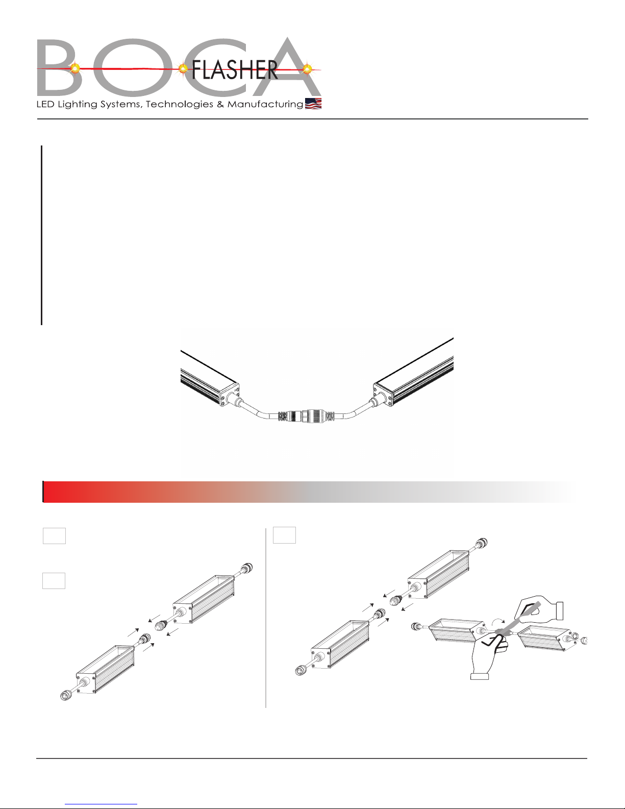
CAUTION: Before installing any type of clip (xed, swivel or arc) onto the mounting surface determine if the xtures have
rigid or twist lock connections at each end (examples of the rigid and twist lock types are shown in section 4).
FIGURE A: CLIP ALIGNMENT
PAGE 3 OF 8
Installation of clips for light fixtures
with RIGID Connections
1. Light fixtures that have rigid connections on each end must be installed in the same plane and must also be in a straight alignment.
Using a chalk line or laser, mark a line on the flat surface where the clips are to be mounted. Align each clip to the chalk line using
the same reference point on each clip (clip edge or hole) and space the clips according to the length of each fixture (see figure A).
Clip placement: Boca Flasher recommends clips to be installed 1.5” from end cap. (see figure 3A)
2. Snap in the first light fixture into the clips (see section 2, installing fixtures into clips). Snap the 2nd. light fixture into adjacent clips
ensuring that the connections will mate (male to female).
3. Slide the second light fixture into the first light fixture until fully seated.
4.CAUTION DO NOT MATE FIXTURES THAT ARE NOT IN LINE OR FORCE
THIS CAN CAUSE PERMANENT DAMAGE TO FIXTURE CONNECTION AND OPERA
TOGETHER BY WIGGLING.
TION.
5.Continue this process until all light fixtures are installed according to the job specific layout drawings.
6.Connect fixtures to power per section 4 and 5.

Installation Instructions
HPNFC-HO
PAGE 4 OF 8
1. INSTALL CLIPS INTO SUBSTRATE
Place the notch on the clip
into the rst notch of the
xture.
1a
Fixed Clips
1b
1a
Swivel Clips
1b
2a
3” Arc & 6” Arc Bracket Installation
Screw Information:
1.
2.
Screws not provided by Boca Flasher.
Boca Flasher recommends wide
washer pan head Phillips #8 screw
(not to exceed .418” in diameter).
3. Length of screw will vary depending
on mounting surface.
4. For outdoor installations, installer
should use a screw with
weatherproof coating.
1a
1b
2. INSTALL FIXTURE INTO CLIPS
Clip will securely
snap into place.
snap!
▶
▶
Fixture will pivot on notch as
it is pushed down.
2b If using the Swivel Clip
or Arc Bracket loosen the
screw where the clip and
swivel bracket meet to ad-
just angle of the xture.
2c
▶
Second Notch
▶
Detent
Angle
Screw
▶
▶
Install security screw using
supplied screw and driver.

FIXTURE LENGTH FIXTURE LENGTH
Installation Instructions
HPNFC-HO
PAGE 5 OF 8
3. CLIP POSITIONING
12
12
FIXTURE LENGTH
FIXTURE LENGTH
Fixed Mounting Clip
3a
Swivel Mounting Clip
3b
FIXTURE LENGTH
FIXTURE LENGTH
Arc Mounting Clip
3c
Changing fixture mount angle adjustable swivel clips only
1. Loosen screw shown on figure 1, on both ends of light
fixture.
2. Adjust light fixture to desired angle.
3. Tighten angle screw to lock into position.
Figure 1
▶
Adjustable Angle Screw
Note: If angle screw can not be reached using a straight
Phillips screwdriver an offset Phillips screwdriver may be
required.
Installation Instructions
HPNFC-HO
PAGE 6 OF 8
Installation of clips for light fixtures
with TWIST LOCK Connections
1. Light fixtures that have twist lock connections on each end may be installed in areas where the surface plane may be at slightly different
levels between fixtures. Also, the light fixtures do not have to be in straight alignment and can be laid out to different angles and patterns.
2. Using a chalk line or laser mark a line on the flat surface where the 2 clips for the 1st. fixture are to be mounted. (See Figure: A)
3. Snap in the first light fixture into the clips (see section 2 installing fixtures into clips).
4. Using a chalk line or laser mark a line on the flat surface where the 2 clips for the 2nd fixture are to be mounted, this fixture can be placed on
a slightly different plane as long as the cord between the 2 fixtures is long enough. Also, this fixture can be placed at a different angle than
the first fixture (see figure 4).
5. Snap in the 2nd light fixture into the clips (see section 2 installing fixtures into clips).
6. Continue this process until all light fixtures are installed according to the job specific layout drawings.
7. Connect fixtures to power per section 4and 5.
Figure 4
See above for information
on determining layout.
Connect Male and Female
twist lock cables in
order shown on job
specic drawings.
Push together and then twist until
completely connected and sealed
if outdoors.
4c
4b
4a
4.coNNect fIxtuRes toGetheR
twISt LOCK COnnECtIOn
Add tape to twist locks.
Place thumb over tape at starting point and
PULL around connector area until tape overlaps itself.
For weather-tight applications only
See additional instructions for weather-tight tape
Installation Instructions
HPNFC-HO
PAGE 7 OF 8
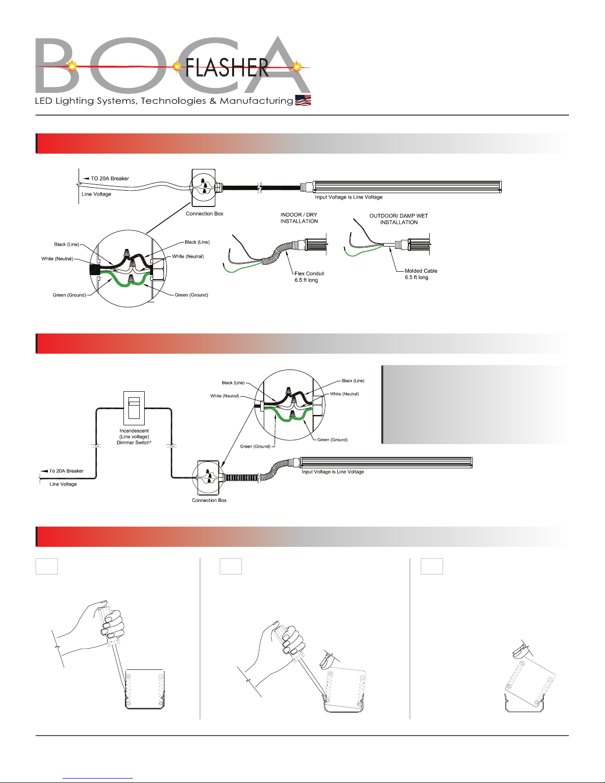
5.coNNect fIxtuRes to PoWeR
6.coNNect to A DIMMING systeM
7.ReMoVING fIxtuRes fRoM clIPs
IF NECESSARY
7aWhile holding the xture with your
other hand, pull back on screwdriver
to release from notch.
Slide a flat head screwdriver in 7b
between the clip and xture.
Once released from one notch,
xture can be fully removed.
7c
*NOTE:
These xtures can dim on forward (leading)
or reverse (trailing) phase dimmers.
Boca Flasher does not recommend the use of
a “Smart” or phase-adaptive dimming module.

Installation Instructions
HPNFC-HO
IMPORTANT SAFETY REMINDERS:
We are constantly improving our fixtures and reserve the right to change options and specifications. Additional information & details at www.
bocaflasher.com. For specific requirements, contact your Boca Flasher sales representative. Boca Flasher, Inc. 552 NW 77th Street Boca Raton,
Florida 33487 USA Phone: 561.989.5338 Fax: 561.982.8323 © 2015 Boca Flasher, Inc. All rights reserved. All names and trademarks are property
of their respective owners. REV 07-2017
DAMP LISTING
IP65
WET LISTING
IP68
1. DANGER:
To reduce the risk electric shock, always unplug the HPNFC-HO from electrical outlet before
cleaning. Cut breaker if outlet is not available.
2. To reduce the risk of burns, re, electric shock or injury to persons:
• UsetheHPNFC-HOonlyforitsintendeduseasdescribedintheseinstructions.
• DonotuseattachmentsnotrecommendedbyBocaFlasher.
• NeveroperatetheHPNFC-HOifithasadamagedcord,cableorplug,ifitisnotworking
properly, if it has been dropped or damaged, or dropped into water. If the seal appears to
be damaged/broken/torn return the xture to a service center for examination or repair.
• Keepcablesawayfromheatedsurfaces
• Neverdroporinsertanyobjectintoanyopening.
• Donotoperatewhereaerosol(spray)productsarebeingusedorwhereoxygen
is being administered.
3. WARNING:
Do not attempt to install or use the HPNFC-HO without reading the installation instructions
and safety labels. Failure to adhere to these instructions could result in serious injury
or property damage.
4. Do not modify, alter or attempt to service the HPNFC-HO:
Doing so will void the warranty.
5. There are no serviceable parts within the HPNFC-HO:
Please contact your local representative if issues arise on site during or after installation.
6. Do not use sharp tools near or on the xture lens:
Doing so will result in property damage and void the warranty.
Boca Flasher, Inc.
508 S. Military Trail nDeerfield Beach, Florida n33442 USA
Phone: 561-989-5338 nFax: 561-982-8323
www.bocaflasher.com
Table of contents
Other Boca Flasher Outdoor Light manuals


