BOCI BLT682H User manual
BLT682H Product Manual
BOCI

BLT682H Product Manual
1
Document History
Number
Date
Version
01
2023/02/09
V1.1
02
2023/02/23
V1.2
Notice:
Thank you for choosing the BLT intelligent cutting head. This manual provides you with
important information such as product parameters, installation, and maintenance, so
please read this manual carefully before using the product. At the same time, in order to
ensure the safety of operation and the operation of the product in the best condition,
please strictly follow the precautions in the manual.
BOCI is constantly updating/upgrading products, so our company reserves the right to
modify the product models and descriptions in this manual without prior declaration.
Unauthorized disassembly of the product is strictly prohibited without the
authorization of BOCI Technology, otherwise the warranty will be invalid!
BOCI

BLT682H Product Manual
2
Table of Contents
1. Product Description .......................................................................................... 4
1.1 Product View ........................................................................................................................................................................... 4
1.2 Technical parameters ........................................................................................................................................................... 5
1.3 Meaning of LED indicator .....................................................................................................................................................6
2. Gas interface...................................................................................................... 7
3. Water cooling interface................................................................................... 8
4. Electrical Interface............................................................................................ 9
4.1 Bus system ............................................................................................................................................................................. 10
5. Cutting head installation ............................................................................... 11
5.1 Preparation before operation ...........................................................................................................................................11
5.2 Specific operation process .........................................................................................................................................................12
5.2.1 Preparation of clean bench ................................................................................................................................... 12
5.2.2 The cutting head is placed in the clean workbench ........................................................................................12
5.2.3 Clean and wipe the fiber interface of the cutting head ................................................................................. 13
5.2.4 Check the laser fiber end face...............................................................................................................................13
5.2.5 Tear off the protective film/remove the protective cap................................................................................. 13
5.2.6 Insert the laser fiber interface into the cutting head...................................................................................... 14
5.2.7 Wrap and seal ........................................................................................................................................................... 14
5.2.8 Mount the cutting head on the backplane........................................................................................................ 15
5.2.9 Installing the ceramic body and nozzle ............................................................................................................. 16
5.2.10 Beam centering .......................................................................................................................................................17
Appendix A - Maintenance ................................................................................ 19
1.1 Schematic diagram of product structure .......................................................................................................................19
BOCI

BLT682H Product Manual
3
1.2 Replace the upper protective lens...................................................................................................................................20
1.3 Replace the lower protective lens ................................................................................................................................... 21
Appendix B - Mechanical Dimensions............................................................ 22
1.1 Cutting head installation size ........................................................................................................................................... 22
1.2 BLT682H Fiber Interface types ................................................................................................................................................24
1.3 Mechanical Dimension ....................................................................................................................................................... 24
BOCI
BLT682H Product Manual
4
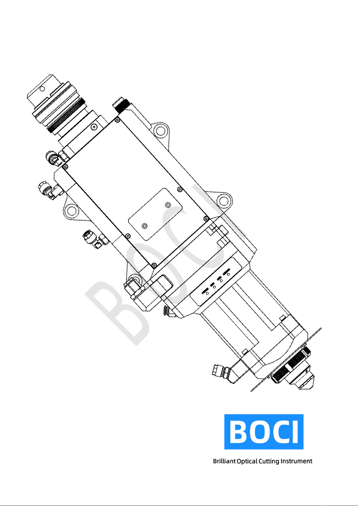
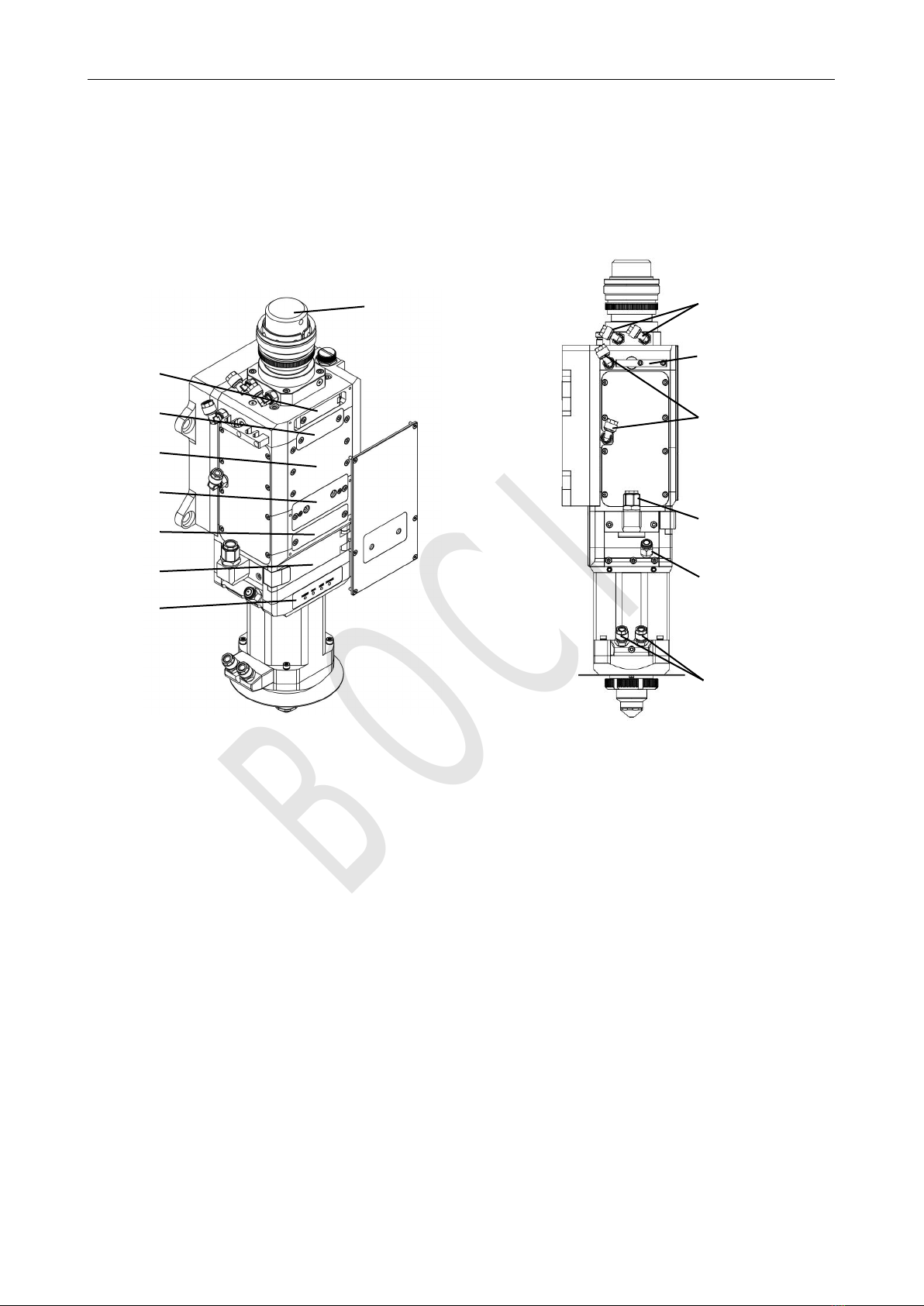
1. Product Description
1.1 Product View
Product View (Structure and Interface Description)
1. Optical fiber interface; 10. Fiber cooling interface;
2. Front Cover; 11. Pipe fixation;
3. 1st Upper protective lens; 12. Cooling water inlet;
4. 2nd Upper protective lens; 13. Cutting gas inlet;
5. Collimation unit; 14. Nozzle cooing gas;
6. Focusing unit; 15. Amplifier Cooling water;
7. 2nd Lower protective lens;
8. 1st Lower protective lens;
9. Working indicator;
1
8
6
5
7
3
4
9
2
10
12
13
14
15
11
BOCI

BLT682H Product Manual
5
1.2 Technical parameters
Cutting head
BLT682H
Laser wavelength:
1030-1090nm
Laser power:
30kW
Fiber interface:
Q+,ADD
Spot magnification:
M=2.0/3.0
Focus adjustment range:
±50mm (optical ratio 1:2 100:200)
NA:
Max.0.14 at Fc100
Max.0.13 at Fc150
Centering adjustment range:
±1.5mm
Focus acceleration:
7.5m/s²
Cutting gas interface:
ø10, maximum 25bar (2.5Mpa)
Nozzle cooling gas connection:
ø6, maximum 5bar (0.5Mpa)
Water cooling interface:
ø8, maximum 5bar (0.5Mpa), minimum flow 2.0l/min
Operating temperature:
5~55℃
storage temperature:
-25~+55 ℃
size:
498x181
weight:
About 10.6 kg F300; F200 9.5kg
BOCI

BLT682H Product Manual
6
1.3 Meaning of LED indicator
icon
state
meaning
green
Power is normal.
red
Under-voltage alarm: insufficient electrical power.
not
bright
No power supply: There is no power supply, the connection cable is broken, and the
interface is loose.
icon
state
meaning
green
The system is operating normally.
red
Abnormal motor: The current consumption of the motor is too large, and the
mechanical components cannot run smoothly.
not
bright
The cable is broken, and the interface is loose.
icon
state
meaning
green
System communication is normal.
red
System communication is abnormal.
not
bright
The cable is broken, and the interface is loose.
icon
state
meaning
green
The readings of each sensor are normal.
red
There is an abnormal sensor reading.
not
bright
The cable is broken, and the interface is loose.
BOCI
BLT682H Product Manual
7
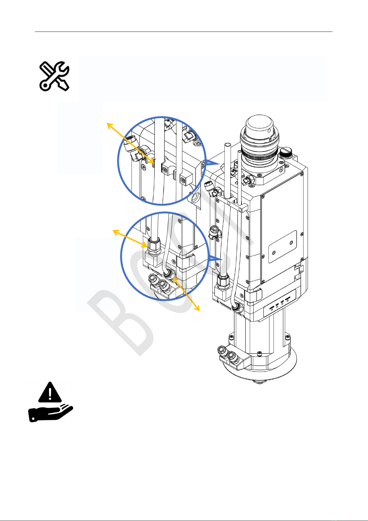
Connect the cutting gas pipe to the cooling gas pipe of the nozzle and tighten it with
a wrench.
Installation connection: cutting gas 1,
nozzle cooling gas 2
Notice:
The maximum pressure of cutting gas is 25bar (2.5Mpa).
The cutting gas quality shall meet the requirements of gas quality in accordance with ISO
8573-1:2010: solid particles - class 2, water - class 4, oil - class 3. The purer the cutting gas,
the longer the life of the protective lens.
The cutting gas pipe diameter (outer diameter) is 10mm, and the nozzle cooling gas pipe
diameter (outer diameter) is 8mm.
2. Gas interface
Note: When using
φ 12 air pipe, the
air pipe interface
of φ 12 in the
fitting box needs to
be replaced.
Cutting Gas
Interface
Nozzle Cooling
Gas
Note: When using
φ12 air pipe, the
air pipe interface
of φ12 in the
fitting box needs to
be replaced.
BOCI
BLT682H Product Manual
8
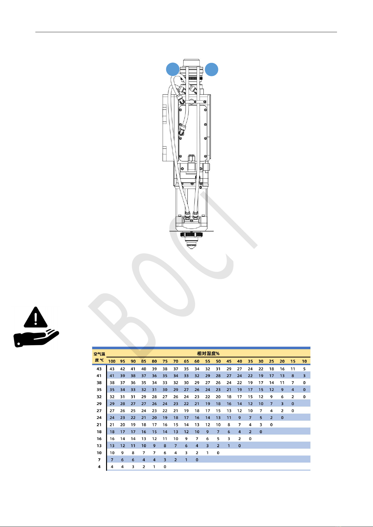
3. Water cooling interface
Installation connection: water-cooled water inlet port 2A, water-cooled water outlet port 1A
Notice:
Deionized/distilled water (conductivity < 10 μ S/cm) specified by the laser manufacturer is
recommended.
Recommended cooling water setting value: cooling water pressure ≤5bar (0.5Mpa), water flow rate ≥
2.0l/min.
Please refer to the dew point table to set the cooling water temperature to prevent condensation on
the optical components.
Dew point temperature at different temperature and humidity
Water
cooling
water outlet
Water
cooling
water inlet
1
2
BOCI

BLT682H Product Manual
9
4. Electrical Interface
PWE and aviation plug interface waterproof precautions:
1. PWE interface and air plug interface are equipped with dust plugs from the
factory. If the dust plug does not fall off, the protection level of IP64 can be
achieved; at the same time, when the PWE cable and the air plug cable are
well connected, IP64 can also be achieved;
2. After the dust plug is removed, the protection level of IP64 cannot be achieved.
If it encounters spraying or flushing at this time, it will cause water to enter the
product and affect the function;
3. Ensure that the water circuit is connected well, and the water pipe interface is
tightened before removing the dust plug to prevent the water pipe from
accidentally loosening and water rushing to the interface, causing the product
to enter the water;
4. When adjusting the wiring, remove the dust plug for wiring. It is recommended
to keep the removed dust plug of the PWE interface. Install the dust-proof plug
as soon as possible after the stitches are removed to prevent accidental water
ingress in the transfer, water connection and other links.
BOCI
BLT682H Product Manual
10
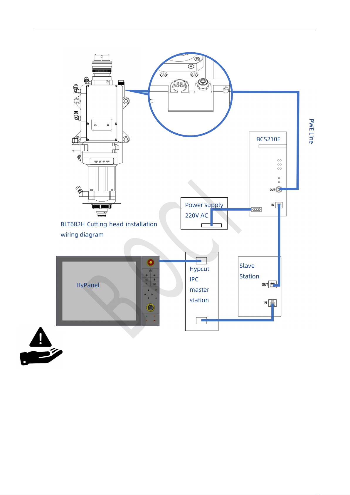
4.1 Bus system
Notice:
The above wiring operations should only be performed by
trained and professional personnel.
When the cutting head is connected to the BCS210E, the
BCS210E must be powered off.
BOCI
BLT682H Product Manual
11
5. Cutting head installation
5.1 Preparation before operation
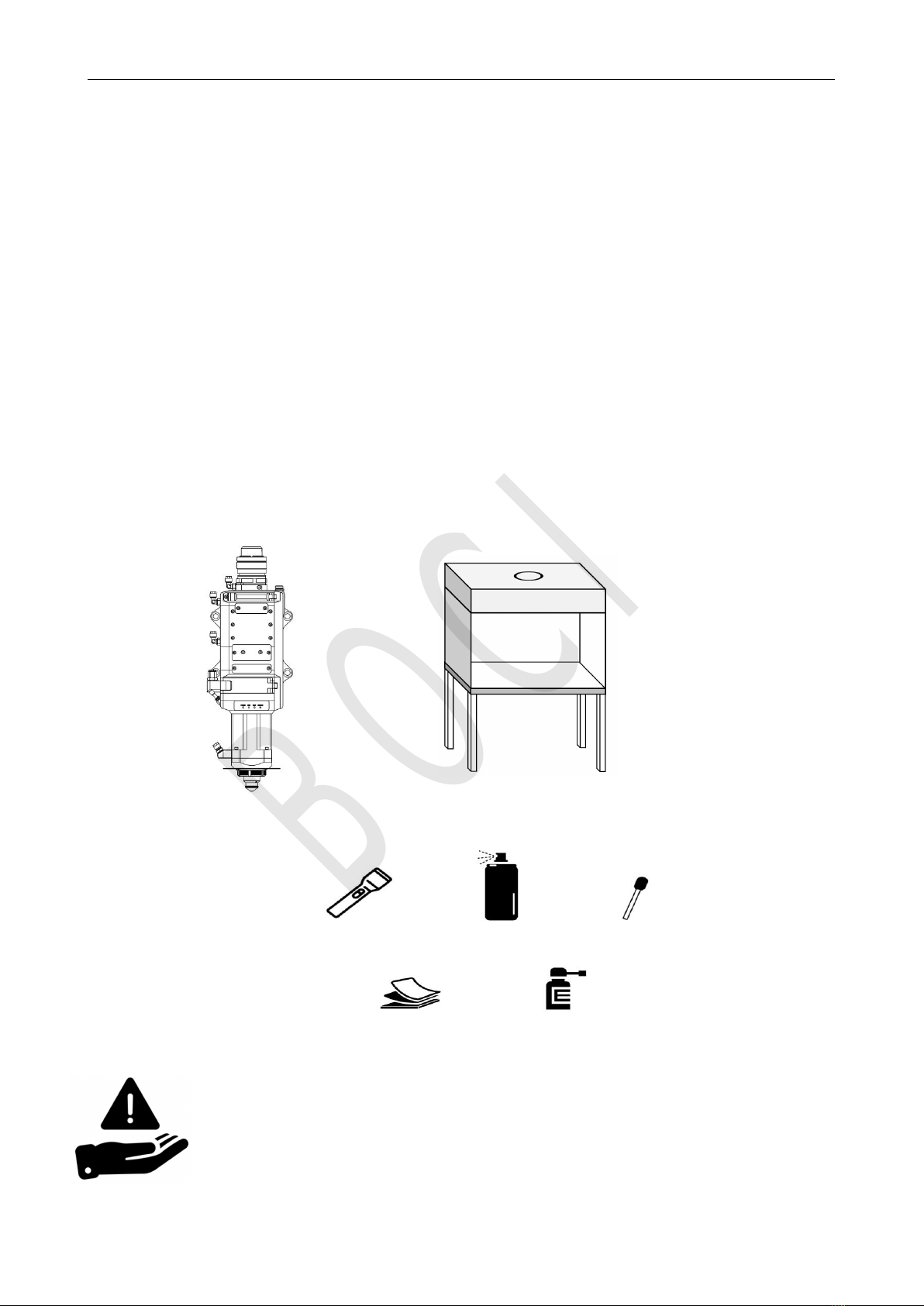
The following objects are required before operation:
Cutting head;
Clean workbench (clean workbench type: vertical purification; cleanliness level: ISO 5, 100; average wind
speed ≥ 0.4m/s);
Cleaning kit: strong light flashlight, absolute ethanol (or IPA), dust-free purification cotton swab, dust-free
cloth, compressed air dust removal tank (or air blower).
During the installation of the cutting head, dust or dirt may accidentally enter the cutting head, contaminate
the optical lens, and affect its normal functions. To prevent dust or dirt from entering the cutting head, please
refer to the following methods for the installation of the cutting head:
Cutting head
clean workbench
Flashlight Ethanol Dust-free cotton swab
dust-free cloth Compressed air dust removal tank
Purification
Kit
Notice:
The above operations can only be carried out by personnel who have received
appropriate training and have professional knowledge.
In order to ensure the normal operation of the laser device and the safety of
operators, please be sure to follow the relevant operating instructions.
BOCI
BLT682H Product Manual
12
5.2 Specific operation process
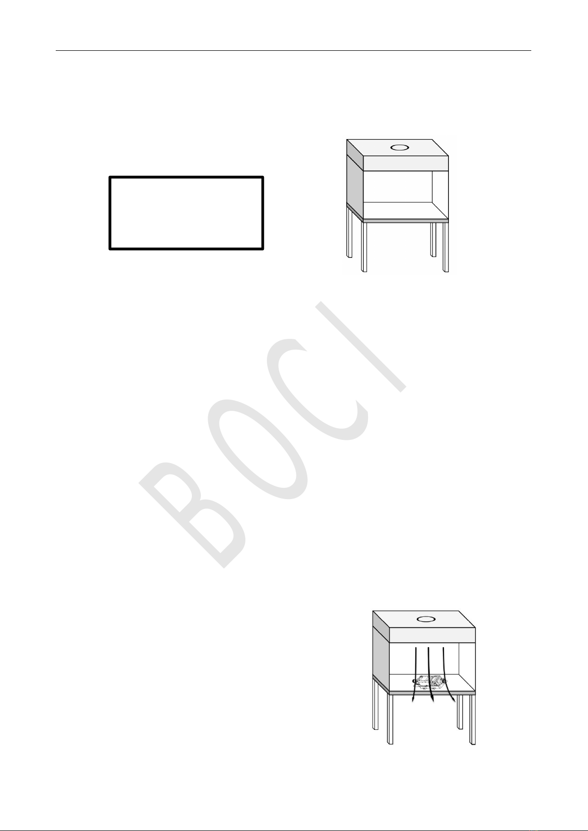
5.2.1 Preparation of clean bench
Prepare the clean bench, start it up and ensure its functionality:
1. Check that the equipment is clean and qualified (checks the cleanliness of the dust particle counter ),
and confirm that the FFU purification unit is within the validity period (measure the average wind speed in the
working area, when the wind speed cannot reach 0.3m/s, the FFU purification unit must be replaced);
2. Check whether each switch is running normally, and check whether the fan is running normally;
3. It is strictly forbidden to install unnecessary items in the clean working area to ensure that the clean air
flow is not disturbed;
4. For clean workbenches that are newly installed or have not been used for a long time, please use a
clean cloth and anhydrous ethanol to wipe them clean before use;
During operation:
1. Turn on the power, and pull the glass sliding door of the clean workbench to the lowest position
(leaving a gap of about 10cm);
2. Start the fan, it is recommended to purify the clean table for about 30 minutes in advance;
3. Turn on the light source of the clean workbench.
5.2.2 The cutting head is placed in the clean workbench
Put the cutting head horizontally inside the clean workbench.
Clean table type: vertical
purification; cleanliness class:
ISO 5, 100; average wind speed
≥ 0.4m/s
Notice:
To prevent dust from contaminating the core area of
the cutting head, please ensure the integrity of the
special protective film/cap for the optical fiber
interface before plugging and unplugging the
optical fiber.
BOCI
BLT682H Product Manual
13
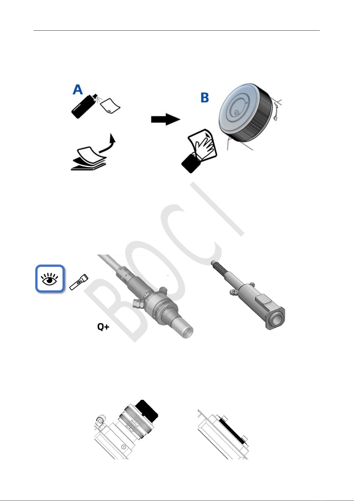
5.2.3 Clean and wipe the fiber interface of the cutting head
Wipe the fiber interface of the cutting head with a clean cloth and anhydrous ethanol.
5.2.4 Check the laser fiber end face
Remove the protective cap of the laser fiber, and irradiate the end face of the fiber with a strong flashlight to
observe whether there is any pollution; if it is clean, you can directly insert the fiber;
5.2.5 Tear off the protective film/remove the protective cap
Remove the special protective cap/protective plug for the optical fiber interface on the cutting head.
ADD
BOCI
BLT682H Product Manual
14
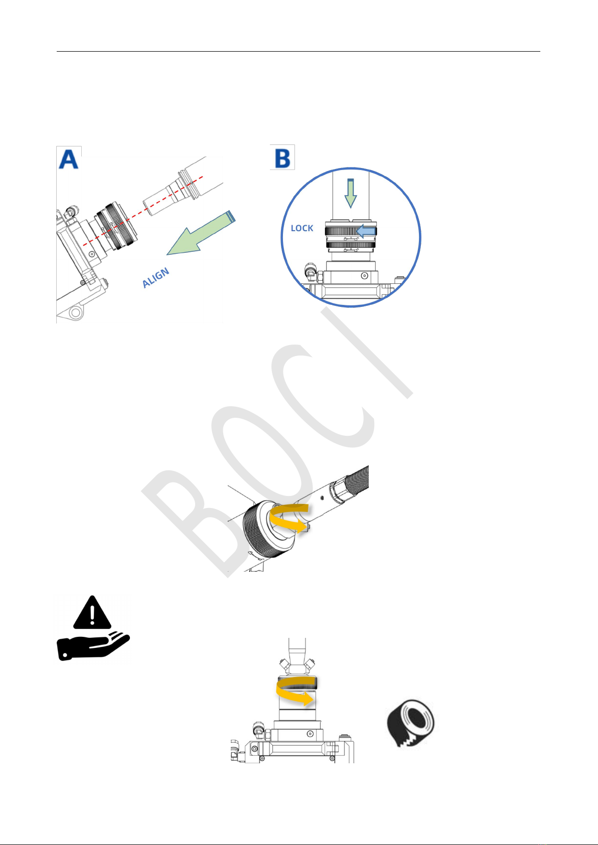
5.2.6 Insert the laser fiber interface into the cutting head
Align the fiber optic plug with the red dot, insert it into the unlocked fiber optic port, and ensure that it is
inserted as far as it will go. Rotate the lock cap until it tightly locked.
5.2.7 Wrap and seal
After inserting the optical fiber, wrap and seal the interface between the optical fiber and the cutting head
with tape.
Notice:
To achieve affective sealing, it is recommended to wrap the
tape at least three times for sealing.
BOCI
BLT682H Product Manual
15
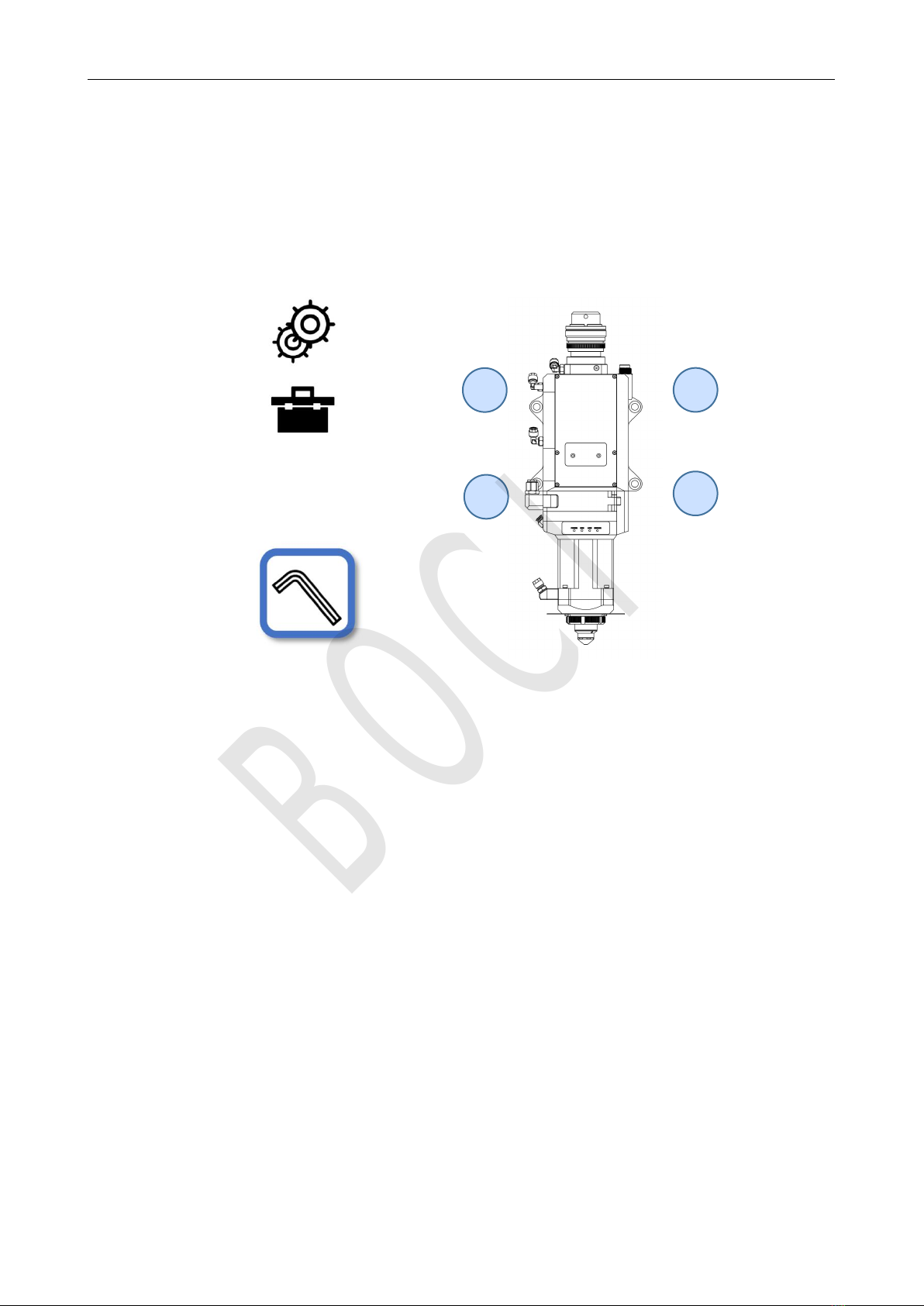
5.2.8 Mount the cutting head on the backplane
The cutting head can be installed on the Z-axis backplane of the machine tool through four screws A, B, C,
and D. When fixing the cutting head on the machine, it must be ensured that the cutting head is locked and there
is no obvious movement.
A
B
C
D
BOCI
BLT682H Product Manual
16
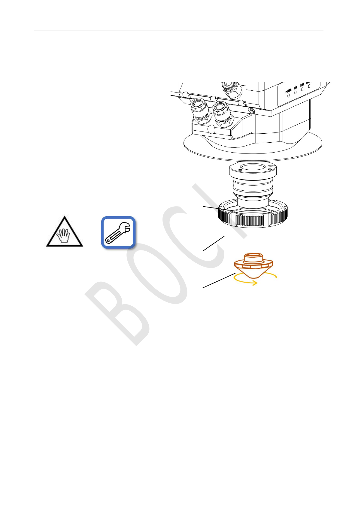
5.2.9 Installing the ceramic body and nozzle
Install the ceramic body and secure with the locking ring, then install the nozzle.
ceramic body
locking ring
nozzle
Tighten the nozzle on the ceramic
body by hand,
Use a wrench to tighten the ceramic
BOCI
BLT682H Product Manual
17
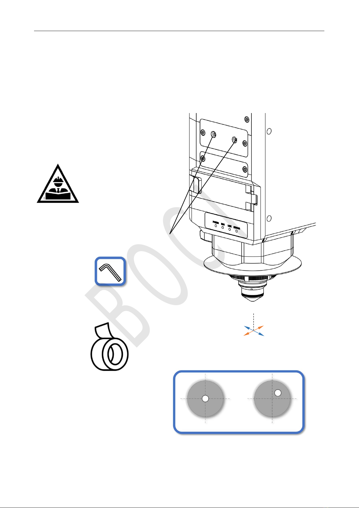
5.2.10 Beam Centering
Adjust the XY centering knob to make the focal point in the center of the nozzle by low-power dotting.
Tape
Fail
Relative position of laser beam
pass
The conditioned laser
beam must be in the
center of the nozzle.
X/Y
adjustment
screw
BOCI

BLT682H Product Manual
18
Manual Alignment Operation:
1. Make sure the laser beam is turned off.
2. Place scotch tape under the nozzle.
3. Click to trigger a low-power laser pulse and assess the position of the laser beam relative
to the nozzle through the penetration of the tape.
4. Adjust the X/Y centering screws to center the laser beam on the nozzle.
BOCI
BLT682H Product Manual
19
Appendix A - Maintenance
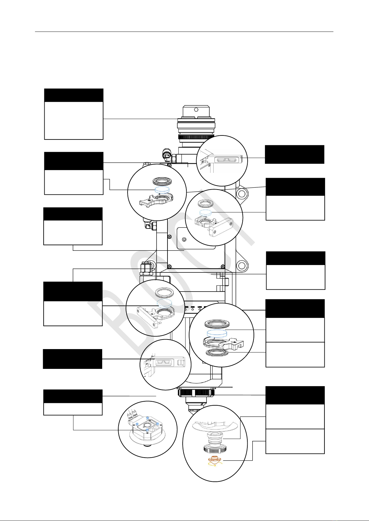
1.1 Schematic diagram of product structure
Fiber Interface
Q+
ADD
2nd Lower Protective Lens
Drawer
2nd Lower Protective Lens
D34x5mm
Collimation Drawer Unit
Collimating Length
F100mm
Upper Protective Lens
D25.4x4mm
Upper Protective Lens
Drawer
1st Lower Protective Lens
Drawer
1st Lower Protective Lens
D34x5mm
Spring Seal
38.5x30.5x3.7mm
2nd Upper Protective Lens
Drawer
2nd Upper Protective Lens
D25.4x4mm
Focusing Lens Unit
Focusing Length
F200mm/F300mm
1st Lower Protective Lens
Drawer Door
Upper Protective Lens
Door
Nozzle
M11,H15
Capacitive Sensing
Module
Ceramic Part
D41mm,M11
Anti-Collision Set
Anti-Collision Screws
BOCI
Table of contents
Other BOCI Industrial Equipment manuals


Popular Industrial Equipment manuals by other brands


FläktGroup
FläktGroup ECONET Installation & maintenance manual

WAMGROUP
WAMGROUP SPECO CPS 200 Installation, operation and maintanance

ABB
ABB HT610734 Operation manual

Motrona
Motrona SinCos SI220 operating manual

SABROE
SABROE HPC 100 Mk 4 LL operating manual

ATS
ATS Pressure Aging Vessel 4 instruction manual