9
LIQUID-COUPLED HEAT EXCHANGER ECONET®
Installation & Maintenance Manual
9
FläktGroup DC_9010GB 20180327_R0 Specifications are subject to alteration without notice
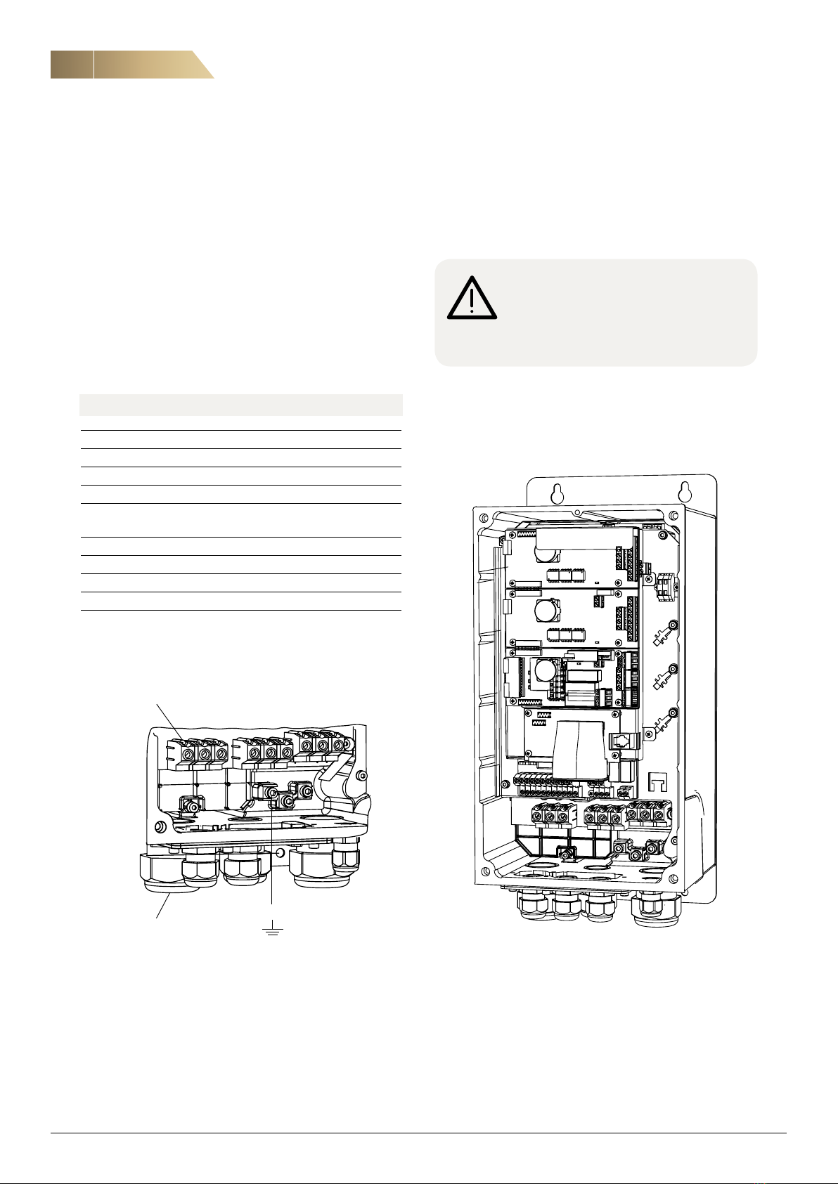
ECONET®ASSEMBLY AND INSTALLATION
GENERAL ADVICE
Failure to observe general advice and installation requirements
can lead to the risk of damage.
Flushing the pipe system:
– ECONET®pump units are cleaned and flushed at the factory.
When flushing the remainder of the system, we recommend
that the pump unit is disconnected and that the P40 pump is
not used during flushing.
It is extremely important to remove all the flushing/cleaning
fluid from the system before filling with antifreeze as a
chemical reaction can occur between the cleaning and anti-
freeze liquids. As the coils cannot be emptied completely,
they must not be exposed to the cold without anti-freeze
recovery.
Filling:
– For optimal heat recovery, we recommend an approximate
25-35% ethylene glycol mixture. Max mixture for the pump
is a 40% ethylene glycol mixture. The P40 pump should not
be used when filling the system.
Use a separate filling system, e.g. a separate pump with a
non-return valve for filling the system, e.g. a hand pump.
– Fill until a static pressure of 1-1.5 bar is obtained on the
suction side of the pump to avoid the risk of pump cavitation.
– Uses premixed anti-freeze liquid, type ethylene glycol/ water
mixture. Prevent exposure to oxygen. When using concen-
trated ethylene glycol, it must be mixed with distilled water.
The liquid must be mixed 24 hours in advance, so that the
mixture will be free of micro bubbles. When filling with pre-
mixed liquid from a tanker lorry, ask for a flushing certificate.
– Mark the system with a label showing the actual flow, type
of anti-freeze liquid, and concentration.
– Check for, and seal any leaks.
– Check that the anti-freeze liquid used has sufficient protec-
tion against corrosion, anti fouling and biological growth.
Follow the instructions of the anti-freeze liquid manufacturer
Air purging:
To get rid of all air in the system takes time, but is vital for the
performance. Use automatic air purge valves combined with
manual air purge valves. Prevent the risk of contamination
blocking the sealing and jeopardizing the shut-off function of
the automatic air purge valve. Install a filter if there is a conti-
nuous problem with contamination. When the system is free of
all air, make sure that all automatic air eliminators are OK and
all manual valves are closed.
Open and close all valves a couple of times. Start the Econet®
pump. The pump should be run manually via the frequency
inverter at maximum 30 Hz.
Under no circumstances must the pump be allowed to run
dry, due to the risk of damage to the seals. Purge the air from
the pump with its own purging valve. Make sure that the system
pressure is maintained at 1–1.5 bar. Refill the system con-tinu-
ously as the pressure decreases. If the pressure drops below
0.5 bar, there will be an A-type alarm from the controller.
Miscellaneous:
– Under no circumstances may the P40 pump be run dry.
This is because the pump will be damaged by the air,
resulting in leakage.
– The coils in the AHU have to be installed with separate shut-
off valves. The total pressure drop for the heat exchangers
on the secondary side must not exceed 40 kPa at the maxi-
mum liquid flow for a closed heat recovery circuit, in the
case of a higher pressure drop in the exchangers then it
should be taken into account when dimensioning the system.
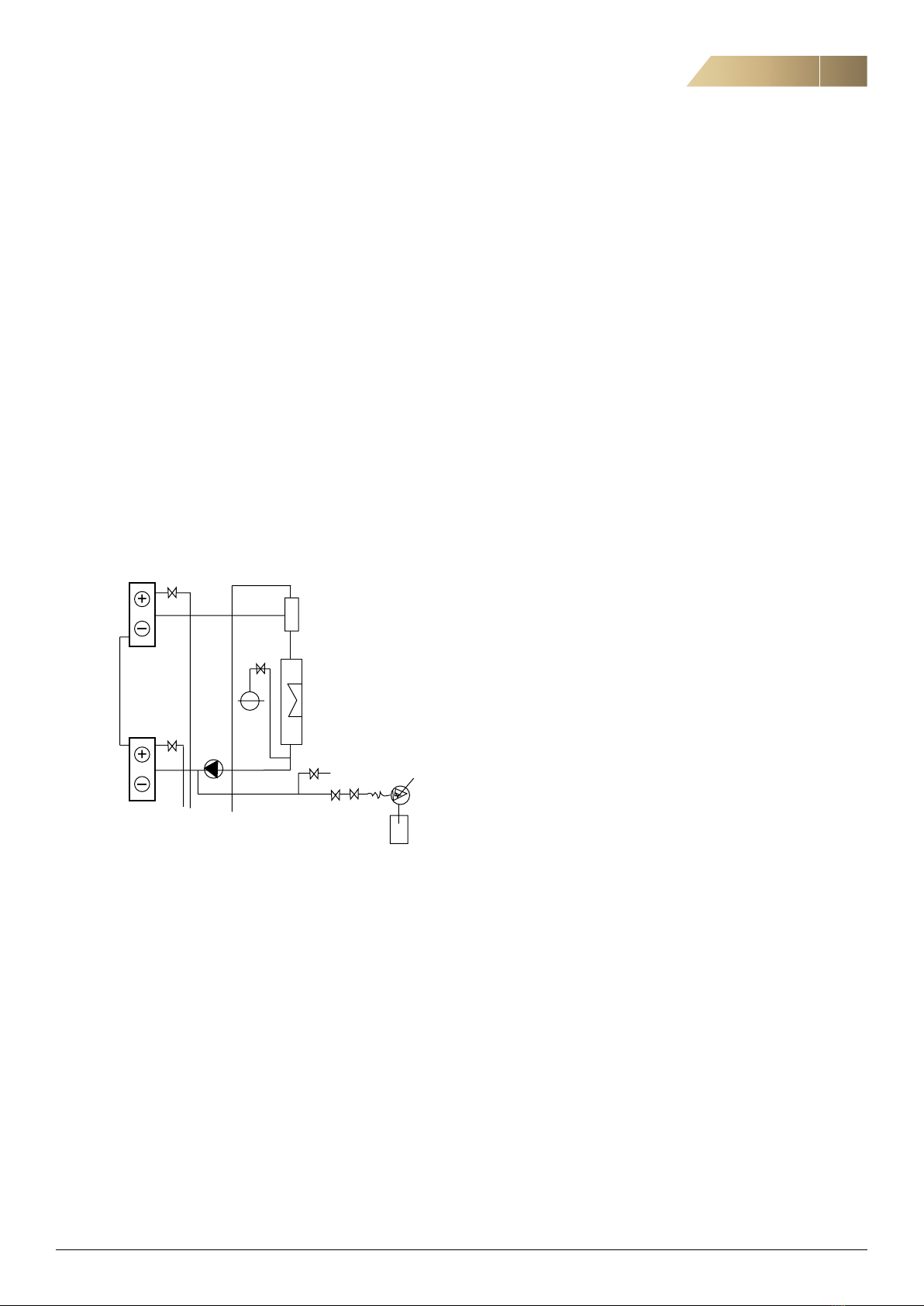
The purging, safety valve and drain connections must be
routed to the connection vessel next to the unit.
– Use air purge valves that can handle micro bubbles (type
Spirovent or Flamcovent).
– The vessel must be installed on the suction side of the pump
(between the pump and the plate heat exchangers for supple-
mentary energy) with a volume of at least 5 % of the total
system volume and with 1.0 bar pre-pressure, 4.5 bar opening
pressure.
– If the risk of cavitation is present on the suction side of the
pump, it is advisible to install underpressure air eliminators.
The purging, safety valve and drain connections are
routed to the connection vessel next to the unit.