BOCK Nursing domiflex 3 User manual

EN
Assembly and operating instructions
Nursing care beds
•domiflex® 3

EN
2
Dear Customer,
By purchasing a nursing care bed from Hermann Bock GmbH, you are
acquiring a long-lasting health care product with first-rate functionality
and the highest level of safety.
Our electrically operated nursing care beds ensure optimum lying com-
fort while also allowing for the provision of professional care. The focus
here is on the person in need of care, whose confidence must be
strengthened and whose life and health are important to be protected.
With this health care product, we have created the foundation for that
trusting relationship.
For your part, we ask that you fully comply with the safety and operating
instructions in this manual, and with all maintenance requirements, in
order to prevent any equipment malfunction or risk of injury.
Klaus Bock

EN
3
Table of contents
1Instruction and general notes..........................................................................5
1.1 Intended use.................................................................................................5
1.2 Contraindications .........................................................................................6
1.3 Definitions of the groups of persons ............................................................6
1.4 Obligations as operator................................................................................7
1.5 Safety instructions........................................................................................7
1.6 Service life ....................................................................................................9
1.7 Warranty ......................................................................................................9
1.8 Market reference .........................................................................................9
1.9 Installation site requirements ......................................................................9
1.10 Type plate...................................................................................................11
1.11 Type plate for bed with reinforcing bars for 185 kg patient weight ..........11
2General description of the functions .............................................................13
2.1 Adjusting the continuous side rail..............................................................14
2.2 Other side rail variants ...............................................................................16
3Electrical components ...................................................................................17
3.1 Drive units ..................................................................................................17
3.2 Caution: Electric drive system ....................................................................18
3.3 Drive systems .............................................................................................19
3.4 External SMPS (switch-mode power supply)..............................................19
3.5 Connections of the main motor system .....................................................20
3.6 Connections of the drive system with individual drives.............................20
3.7 Operating status display of the external switched-mode power supply unit
20
3.8 Hand contol ................................................................................................21
4Construction and operation ..........................................................................23
4.1 Technical specifications –domiflex® 3 .......................................................23
4.2 The domiflex® 3 model series.....................................................................25
4.3 Assembly and installation videos ...............................................................25
4.4 Assembly and installation –domiflex® 3....................................................26
4.5 domiflex® 3 - Additional steps when attaching the reinforcement bars for
185 kg patient weight..............................................................................................31
4.6 domiflex® 3 –transport system..................................................................32
4.7 domiflex® 3 - Additional steps when attaching the bed extension............36
4.8 Disassembly................................................................................................37
4.9 Relocating the bed......................................................................................38
4.10 Transport, storage and operating conditions.............................................38
4.11 Usage notes................................................................................................38
4.12 Disposal ......................................................................................................39
4.13 Troubleshooting .........................................................................................39
5Product accessories.......................................................................................40

EN
4
5.1 Non-standard dimensions ..........................................................................40
5.2 Lifting pole with triangle grip .....................................................................41
5.3 Side rail padding .........................................................................................42
5.4 Side rail height extender ............................................................................42
5.5 Grab rail with crossbar ...............................................................................42
5.6 Mattresses..................................................................................................43
6Cleaning, care and disinfection......................................................................44
6.1 Cleaning and care .......................................................................................44
6.2 Disinfection.................................................................................................45
6.3 Avoiding hazards ........................................................................................45
6.4 Mechanical cleaning...................................................................................46
7Guidelines and manufacturer declaration .....................................................49
7.1 EU declaration of conformity .....................................................................50
8Safe use in a domestic environment ..............................................................51
9Regular inspections with service ...................................................................52

EN
5
1Instruction and general notes
The different nursing bed systems from Hermann Bock GmbH meet special requirements
for use in nursing and therapy facilities as well as for care at home. At the same time,
reliable functionality and durability distinguish each individual care bed as being of partic-
ularly high quality. With proper operation and inspection, the care bed remains corre-
spondingly maintenance-free. Each Hermann Bock care bed only leaves production after
passing a quality test in the final inspection. The care beds are manufactured and tested
in accordance with the currently applicable standards for medically used care beds.
The Nursing care beds are compliant with the EN 60601-2-52 standard. The electrical com-
ponents are compliant with the EN 60601-1 safety standard for medical devices. Nursing
care beds are medical devices and are categorised as Class 1.
The standard divides nursing care beds into five different usage environments:
1. Intensive care in a hospital, intensive-care bed
2. Acute care in a hospital or other medical facility, patient bed in a hospital
3. Long-term care in a medical environment, stationary nursing care bed
4. Care at home, pure so-called “Home-Care bed”
5. Ambulant care
1.1 Intended use
The nursing care bed is suitable for patients 146 cm or greater
in height and a minimum weight of 40 kg. The patient’s weight
may not exceed the maximum body mass indicated on the
nameplate. The patient’s body mass index (BMI) must be 17 or
greater.
The nursing care bed may be used in nursing or retirement homes and rehabilitation fa-
cilities. Its purpose is to alleviate a patient’s disability and to make it easier for nursing
staff to provide care. In addition, the nursing care bed was designed as a convenient solu-
tion for patients requiring care at home and for people with disabilities. The nursing care
beds described below are thus intended for usage environments 3 to 5 above. Any other
use is incompatible with the intended use and excluded from any claims of liability.
The nursing care bed is delivered without the Trendelenburg function as standard. The
Trendelenburg function is available as an option for application environments 3 and 5.
The Trendelenburg function may only be used by qualified medical personnel. Nursing
beds intended for application environment 4 are equipped with a hand control that can-
not control the Trendelenburg function.

EN
6
The nursing care bed is not suitable for use in hospitals. It is also not designed for trans-
porting patients. The nursing beds are only mobile within the patient's room - also during
patient positioning - for example for cleaning or for better access to the patient.
The nursing care bed is suitable for re-use. Please follow all guidelines in these assembly
and operating instructions for cleaning, care and disinfection of the nursing care bed prior
to re-use. Please pay particular attention to all information about inspecting the bed.
Note: The beds have no specific connectors for equipotential bonding. Electrical medical
devices with intravascular or intracardiac connections to the patient may not be used. The
operator of any medical devices is responsible for ensuring that the combination of de-
vices meets the requirements of EN 60601-1.
This manual contains safety instructions. All persons who work with the beds must be
familiar with the contents of this manual. Improper operation may result in hazards.
1.2 Contraindications
This bed is intended only for patients/residents who meet the following minimum body
size and weight requirements:
•Height of 146 cm or taller
•Weight of 40 kg or higher
•Body mass index of 17 or higher
1.3 Definitions of the groups of persons
Operator
An operator (e.g. a health care supplier, equipment dealer, institution or funding agency)
is any natural or legal person that uses the nursing care beds or on whose behalf the nurs-
ing care beds are used. The operator is always responsible for proper use of the product.
User
Users are persons who are authorised on the basis of their education, experience or prod-
uct training to operate or perform work on the nursing care bed. The user is able to iden-
tify and/or prevent possible hazards and to assess the patient’s state of health.

EN
7
Patient/Resident/Layman
The person requiring care, infirm person, or person with a disability who is lying in the
nursing care bed. An instruction of the resident in the functions of the bed that are im-
portant for him by the operator or the nursing staff is necessary for each new occupancy.
An introduction to how the resident has to behave in the event of unfavourable conditions
of use. See the chapter Safe use in a home environment.
Qualified personnel
Qualified personnel are employees of the operator who are authorised on the basis of
their education or training to deliver, assemble, disassemble and transport the nursing
care bed. In addition to operation, assembly and disassembly of the nursing care bed,
these persons have been instructed in the guidelines for cleaning and disinfecting the
nursing care bed.
1.4 Obligations as operator
In Germany, observe your obligations as an operator in accordance with the Medical De-
vices Operator Ordinance in order to ensure that this medical device can be operated
safely in the long term without any hazards. In other countries, the applicable national
regulations on the obligations of the operator must be observed.
Point out the storage location of these instructions for use to the nursing staff in accord-
ance with the Medical Devices Operator Ordinance. In other countries, the applicable na-
tional regulations must be observed. Instruct the nursing staff in the safe operation of the
nursing bed with the aid of these instructions for use before the initial start-up.
Draw the attention of the nursing staff to possible hazards in case of improper use of the
nursing bed. This applies in particular to the handling of the electrical drives and side rails.
According to the Medical Devices Operator Ordinance (MPBetreibV), operators must rec-
ord their stock of electrically adjustable hospital and care beds (active medical devices)
and keep an inventory.
1.5 Safety instructions
Proper use of all moving components is essential for preventing hazards to the patient
and for the safety of the patient’s family and/or nursing staff. Ensuring proper use requires
proper assembly and operation of the nursing care bed. The individual patient’s physical
condition and the type and extent of their disability must also be taken into account when
using the nursing care bed.
Avoid hazards from accidental motorised adjustments and other incorrect operations by
using the locking mechanism. When the user (e.g. the nursing staff or family member car-
ing for the patient) leaves the room, all of the bed’s functions should be locked using the

EN
8
key on the hand control. To do this, first lower the lying surface to the lowest position,
then activate the locking function by turning the key in the lock located on the back of the
hand control. Remove the key and test the hand control functions to ensure that it has
been properly locked.
It is especially important to follow these recommendations
▪if the patient cannot safely operate the hand control functions themselves
due to certain disabilities,
▪if the patient or nursing staff could be put at risk by unintended adjustments,
▪if the side rails are raised and there is a risk of pinching or crushing,
▪if unsupervised children are present in the room with the nursing care bed.
When not in use, always make sure that the hand control or control unit is securely at-
tached to the care bed with the suspension hook and cannot fall down.
The nursing care bed must only be operated by nursing staff or family members who have
been trained in its use, or in the presence of trained users.
When adjusting the lying surface, it is especially important to ensure that no limbs are
placed within the adjustment range of the side rail. If the side rails themselves are ad-
justed, pay attention to the correct lying position of the person in need of care.
Prior to any electrical adjustment, it should generally be made sure that no limbs are po-
sitioned in the adjustment area between the chassis and the head or foot part, especially
that there are no persons or animals in the area between the floor and the raised lying
surface. The risk of pinching or crushing is particularly high in these areas. Also check for
objects located near or beneath the nursing care bed. Remove such objects to avoid dam-
age during adjustment.
The permitted person’s weight depends on the total weight of the equipment that has
been mounted to the bed (mattresses and other electronic medical devices). For safe
working load, please refer to the type plate on the lying surface frame of the bed
Service and maintenance must not be carried out while the nursing care bed is being used
by a patient.
The nursing care bed may only be used for the care and positioning of people. The adjust-
ment options on the head and foot sides serve exclusively for the changeable positioning
of the respective body area of a patient. The care bed may only be used for its intended
purpose and may not be misused or used improperly.

EN
9
The patient must be immediately removed from the bed in case of malfunction or equip-
ment failure. Use of incompatible side rails may result in entrapment of extremities. To
deactivate the nursing care bed and safely end operation of the bed, remove the mains
plug from the socket.
1.6 Service life
This nursing care bed was designed, engineered and manufactured to operate safely for a
long period of time. When used and operated correctly, this nursing care bed has an ex-
pected service life of 10 years. The service life depends on operating conditions and fre-
quencies.
1.7 Warranty
For your warranty conditions for this nursing care bed, please consult your contact person.
Any unauthorised technical modification to the product shall immediately void all war-
ranty claims.
1.8 Market reference
This product is not approved for the North American market, particularly not for the
United States of America (USA). Distribution and use of this nursing care bed in these
markets, including via third parties, is prohibited by the manufacturer.
1.9 Installation site requirements
Hermann Bock GmbH is not liable for any floor damage that may result from everyday use
of this product. To avoid marks or impressions on the floor, the floor surface should com-
ply with the recommendations of the FEB (Fachverband der Hersteller elastischer Boden-
beläge e. V., the German Trade Association for Elastic Floor Coverings). FEB Technical In-
formation Document no. 3 can be consulted for this purpose.
Bock safety note
When the user, e.g. the nursing staff or caring relatives, leaves the room, the lying surface
should be moved to the lowest position in order to minimise the risk of injury if the patient
falls out.
When the user, e.g. the nursing staff or caring relatives, leaves the room, the complete operat-
ing functions of the nursing bed should be locked using the key of the hand control.

EN
10
Bock safety note
When using multiple electrical devices simultaneously, small electromagnetic interactions be-
tween such devices may occur, e.g. static and distortion on a radio, especially in direct proxim-
ity to the activated nursing care bed. In these rare cases, increase the distance between de-
vices, use a different wall socket, or temporarily switch off the device causing or affected by
the disturbance. If the nursing care bed is to be used with electrical medical devices, contrary
to its intended purpose, then the nursing care bed’s functions must first be deactivated via the
integrated locking function on the hand control for the duration of such use of these devices.
Bock safety note
Ensure that there is sufficient distance between the nursing care bed and any curtains, blinds,
heaters and wall sockets, and ensure that any medications, cords, rubber bands, small toys, or
other small objects like coins cannot be reached from any position in the nursing care bed.
Bock safety note
Ensure that the care bed is placed in such a way that there is easy access to the power supply
to disconnect the care bed from the power supply.

EN
11
1.10 Type plate
Each nursing care bed is marked with both an individual and a general type plate.
Individual and general type plate
(1)
(2)
(3)
(4)
(5)
(6)
(7)
(1) Model
(2) Date of manufacture: Year - Month - Day
(3) Serial number: Order number - Sequential number
(4) Mains voltage, mains frequency and power input
(5) Duty cycle
(6) Drive protection class
(7) Manufacturer
(8) Safe working load
(9) Maximum patient weight
(10) Own weight of the bed
1.11 Type plate for bed with reinforcing bars for 185 kg patient weight
Each reinforcement bar is marked with an individual and a general type plate.
Individual and general type plate
(1)
(2)
(3)
(4)
(5)
(1) Model number
(2) Date of manufacture: Year - Month - Day
(3) Serial number: Order number - Sequential number
(4) Own weight of the bed
(5) Manufacturer
(6) Safe working load
(7) Maximum patient weight
(8)
(9)
(10)
(6)
(7)

EN
12
Explanation of symbols:
Conformity marking for compliance with Medical Device Regulation
Refer to manual
Product is subject to separate waste disposal requirements
in the European Union. Product may not be disposed of in household
waste.
Type B medical applied part
Use only in dry areas
Protection class II (double insulation, protective insulation)
IPX4
Electrical equipment protected from splashing water
Maximum patient weight
Safe working load
Own weight of the bed / reinforcement bars
Medical device marking
Patient population
Follow guidelines for mattress size and thickness
Manufacturer’s address
MD

EN
13
2General description of the functions
Construction and function
Corrosion protection
Nursing care beds from Hermann Bock GmbH are designed and engineered to operate
safely for a long period of time. Therefore, all materials that may corrode are protected
accordingly. All metal parts are treated with surface protection. Steel parts are either gal-
vanised or stove-enamelled with a PES powder coating, and aluminium profiles are ano-
dised.
Four-zone lying surface
The lying surface comes standard with a comfort slatted frame (or can alternatively be
fitted with aluminium slats) and is divided into four functional zones: back rest, fixed seat,
thigh rest and lower leg rest.
The outer edge of the lying surface is constructed from tubular steel. The tubular steel
segments are stove-enamelled with a PES powder coating on their outer surface. Contin-
uous electrical height adjustment is provided by DC motors with safety extra-low voltage
from 29 to 35V and controlled with an easy-to-operate keypad on the hand control. The
back rest can be electrically adjusted. The leg section consists of a two-part foot bar. Each
individual position can be continuously adjusted with the push of a button on the hand
control.
Chassis
Fixed seat
Back rest
Lower leg rest
Thigh rest
EN
14
The height adjustment of the nursing care beds is done by two height-adjustable adjusting
units. The surface of the tubular steel construction is stove-enamelled with a PES powder
coating.
Side rails
Each nursing bed is equipped with two side rails on both sides at a special safety height.
The side rails run in a track and can be raised or lowered by means of a release button.
The sliders are particularly smooth-running due to an impact damper, and the ends are
fitted with a functional locking cap. The ergonomically shaped release button makes it
easy to operate the side rail.
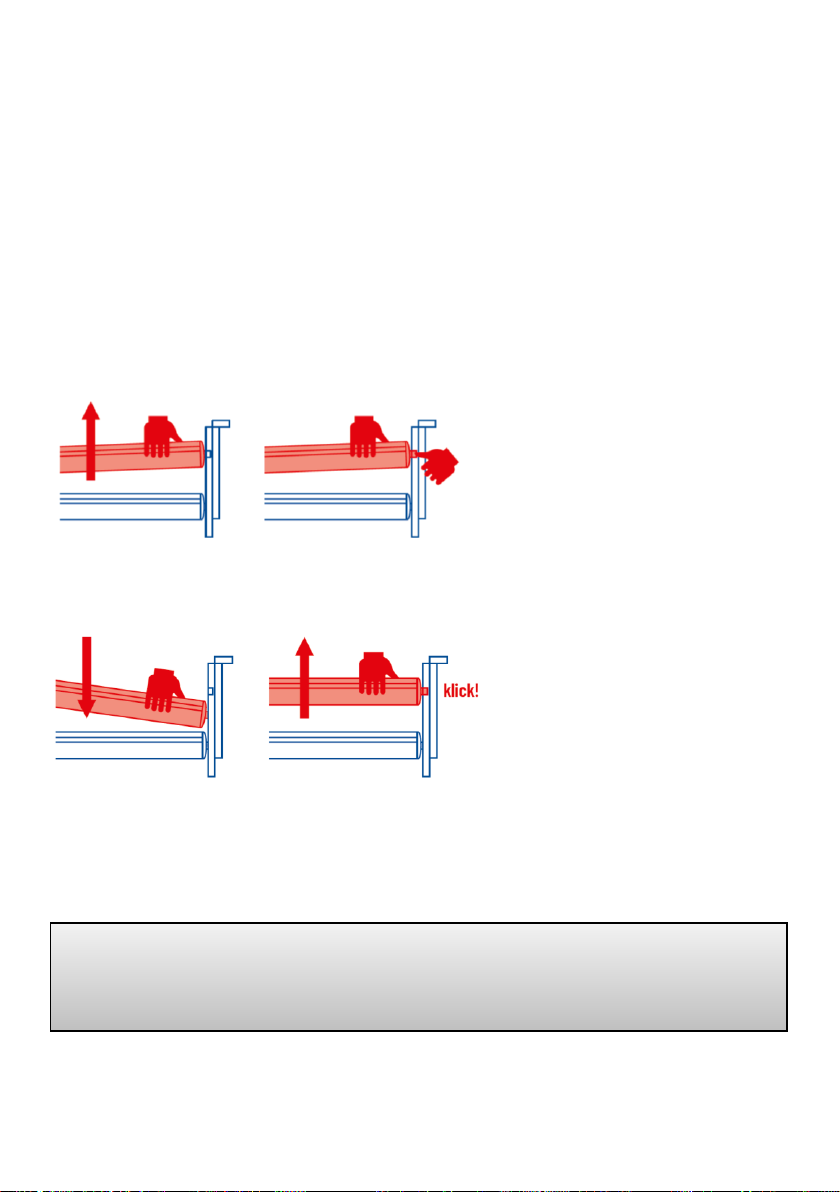
2.1 Adjusting the continuous side rail
The release button for adjusting
the continuous side rails is lo-
cated just above the upper side
rail in the sliding track.
To lower the side rails, hold the
provided gripping groove of the
upper side rail, lift the side rail
slightly, and press the release
button on either the headboard
or footboard. The side rail is then
released on that side and can be
easily lowered to the end of the
track. The side rail is now in a di-
agonal position. To lower the
other side, perform these steps
again at the opposite end of the
bed. The side rail is now in its
lowered position.
Bock safety note
Always lift the side rail slightly before pressing the release button! Failure to do so will damage
the release mechanism.
Step 1: Grip side rail and lift slightly.
Step 2: Press release button.
Note: Be sure to lift the side rail slightly and
the press the release button!
Step 3: Downward lowering.
Note: Both sides must be lowered!
Bring to the top position as fall protection:
Pull the side rails up until it clicks audibly into
place at the ends

EN
15
To raise the side rails to the upper position for protection against falls, hold the upper side
rail in the centre of the groove and pull the side rail up until you hear it click into position
at both ends. The side rail is now in its raised position.
The primary purpose of the side rails is to protect the patient from falling out. For ex-
tremely emaciated patients, the side rails no longer offer adequate fall protection, and
additional protective measures must be taken, e.g. by placing additional fitted side-rail
bumpers (product accessory) in the bed.
The gap between the continuous side rails must be no larger than 12 cm. The side rails
must not be left in a diagonal position during use.
Bock safety note
Always operate the side rails with great care, as fingers can easily be pinched. Only use the
side rails in accordance with the mode of operation described here. Any other use can lead to
increased risks and is prohibited. Use only original Bock side rails. Use only side rails that are
undamaged and free of technical defects, and ensure that the gap between rails is always
within the permissible range. Ensure that the side rails click securely into position.
Before placing the side rails and before each new use, check for damage on all mechanical
parts on the bed frame and the side rails that serve to hold the side rails in place.
Bock safety note
Always be aware of the increased risk of pinching associated with a locked side rail when
adjusting the position of the back and thigh rests.

EN
16
2.2 Other side rail variants
The side rail SR2 can be used with the domiflex® 3. The side rail SR2 comes with its own
installation and operating instructions for the side rail.
Figure 1: Continuous wood/steel side rail system with two elements
All dimensions in mm. * Depending on the length of the lying surface. The dimension
in brackets is optional
Legend
Area Description
A Distance between headboard and side rail
B Side rail height 1
C Side rail height 2
D Side rail length 1
E Distance between elements of the side rail system
F Distance between divided side rails
G Distance between lying surface and top edge of side rail system
H Height of top edge of side rail system
above the mattress without compression
I Mattress thickness in accordance with intended use
J Side rail length 2
K Smallest distance between side rail system and lying surface
L Distance between footboard and side rail
Headboard or
footboard
Headboard or
footboard

EN
17
3Electrical components
3.1 Drive units
Depending on the model, the drive unit consists either of a main motor with two separate
drive units for motorised adjustment of back rest and leg rest positions, or two individual
single drives. The height level of the bed is adjusted by means of one actuator in each end
panel. The motors and the hand control are connected to the internal control box. The
power supply unit converts the input voltage to a safety extra-low voltage of max. 35V DC.
This safety extra-low voltage is used to operate the motors and the hand control. Cables
are double-insulated and the power supply unit has a primary fuse.
The internal emergency lowering mechanism uses a 9V block battery. In addition, a power
adjustment system ensures constant operating speed. These safety measures correspond
to protection class II, and liquid ingress protection meets the standards of protection code
IPX4.
The maximum duty cycle is indicated on the nursing
care bed (type plate). For example, a 10% duty cycle
(2 min. ON / 18 min. OFF) means that each electri-
cally-powered adjustment can be run for no longer
than 2 minutes out of every 20 minutes to prevent
overheating.
If the maximum motor activation time of two minutes
is exceeded, for example due to excessive use of the
hand control, and the motors overheat as a result, the
thermal fuse immediately cuts off all power to the
bed. After a cooldown time of approx. 1 hour, the power supply is automatically restored.
If the lifting drives do not move synchronously and this leads to an inclined position of the
lying surface, move the lying surface height to the upper or lower end position. This ena-
bles an automatic compensation of the two lifting drives and thus a horizontal lying sur-
face.
Bock safety note
The 9-volt batteries in the control unit must be checked once a year and replaced if necessary.
In addition, visual inspections should be conducted on a regular basis.
9V block battery for emergency
lowering (main motor)

EN
18
3.2 Caution: Electric drive system
With its wide variety of functions, the electrically powered nursing care bed provides the
patient with substantial physical and emotional support for their recovery process, while
also alleviating pain. As medical devices, electrically powered beds require a high level of
diligence with regard to regular safety inspections. This includes safe use of the nursing
care bed, daily inspection of electrical equipment, and proper cleaning and mainte-
nance.
To avoid cable damage, cords and cables should be placed outside of any area where dam-
age could occur. Any contact with sharp-edged components should also be prevented. To
avoid risk of injury from electric shock, any possibility of excessive touch voltage should
be eliminated. Such circumstances are especially likely to occur when the mains power
cable has been damaged, when dangerous and excessive leakage currents are present, or
when liquid has entered the motor housing, e.g. as a result of improper cleaning. Such
damage can result in control unit malfunction which can in turn lead to unintended move-
ments of individual bed components, raising the risk of injury to patients and users.
Bock safety note
Do not open any components of the drive system!
Only specifically authorised professionals are permitted to repair any defects or replace indi-
vidual electrical components.
Bock safety note
Cables must not be pinched or crushed. Adjustment of moveable parts may only be used for
the intended purpose. Hermann Bock GmbH assumes no liability for unauthorised technical
modifications.
Bock safety note
Never attempt to repair electrical equipment yourself. In some cases there may be a risk of
life-threatening electric shock! Contact either the Customer Service department at Hermann
Bock GmbH or an authorised professional electrician to repair any defects in accordance with
all applicable VDE guidelines and safety requirements.

EN
19
3.3 Drive systems
The domiflex® 3 is equipped with drives from company Limoss (drive system with external
switching power supply). Depending on the version, the domiflex® 3 lying surface is
equipped with a main motor or separate single drives for head and foot rest.
The main motor for the stepless adjustment of the lying surface and the linear drives as
single drives for the height adjustment at the end panels or the adjustment of the lying
surface, each consist of four main components.
▪Housing
▪Motor
▪Gearbox
▪Spindle with nut
The housing design of the main motor and single drive systems ensures long-term opera-
tion of all drive components. The special construction design is based on two load-bearing
housing shells. The inside of the housing has a detailed internal construction that provides
a precise fit for the drive unit hardware. The housing allows for simple assembly and dis-
assembly, and provides generous space for installation of the emergency lowering battery
and control electronics. The main motor also features a robust side shutter.
3.4 External SMPS (switch-mode power supply)
The drive system includes a primary fuse in the power supply unit and an emergency low-
ering mechanism. The SMPS (switch-mode power supply) is an electronic transformer that
warms up only minimally under load and has an integrated electronic power monitoring
unit. The resulting system provides constant voltage up to the load limit (no loss of speed)
and strong protection against overloading. The external transformer provides safety right
from the wall socket, where it transforms the mains voltage directly into the safety extra-
low voltage used to operate the nursing care bed. It is connected to the mains power
supply cable by means of a plug coupling, so that it can be replaced separately in case of
a defect.
The power supply unit complies with European guidelines for household electrical devices,
so it also maintains low energy consumption of no more than 0.5 watts in standby mode
and can be used internationally with input voltages from 100 V to 240 V. No alternating
electromagnetic fields can be detected at the SMPS, and such fields are even lower during
operation (due to the very low direct current) than when disconnected from mains power.

EN
20
3.5 Connections of the main motor system
3.6 Connections of the drive system with individual drives
3.7 Operating status display of the external switched-mode power supply unit
The switched-mode power supply SMPS has an LED that can indicate the following oper-
ating states:
▪LED On: Ready for operation
▪LED Off: Discharged, not connected
▪LED Flashing: Error, thermal overload, or short circuit.
After disconnecting the mains plug or the connection to the motor, the LED "glows" and
then goes off.
Power Supply
Control box
Hand control
Head rest motor
End panel motor
End panel motor
Leg rest motor
Control box
Hand control
Main motor
End panel motor
End panel motor
Other manuals for Nursing domiflex 3
1
Table of contents
Other BOCK Medical Equipment manuals


Popular Medical Equipment manuals by other brands


C-Aire
C-Aire Companion 5 quick start guide

I-Tech
I-Tech I-TECH LA8000 user manual

IEM
IEM Mobil-O-Graph Instructions for use

Hillrom
Hillrom Yellofin Elite Stirrup Instructions for use

ARJO HUNTLEIGH
ARJO HUNTLEIGH Alpha Active 3 Quick reference guide

Akces-Med
Akces-Med DALMATIAN Use and Maintenance Instruction

I-care
I-care IC333 operating manual

B. Braun
B. Braun VenaTech RETRIEVABLE 04435150 Instructions for use

Atos
Atos MC1968 quick start guide

Cooper Surgical
Cooper Surgical LEEP PRECISION LP-10-120 operating manual

ARJO HUNTLEIGH
ARJO HUNTLEIGH Enterprise 8600 Instructions for use

ARJO HUNTLEIGH
ARJO HUNTLEIGH Streamline 2211 Instructions for use