BOCK adilec 280 Installation instructions

1
Assembly Instruction and User Manual
adilec 280

Dear valued customer,
with your decision to purchase a therapy and rehabilitation bed from Hermann
Bock GmbH, you will receive a durable care product with superior functionality
at the highest safety level. Our electrically operated nursing care beds guarantee
an optimal lying comfort and enable a professional care at the same time. This
product was designed with a focus on persons in need of care, whose confidence
must be reinforced and whose life needs protection. With this health care prod-
uct, we meet these requirements.
We urge you to prevent potential malfunctions and the risk of accidents by com-
plying strictly with the safety and operating instructions and by carrying out the
necessary maintenance.
Klaus Bock

Table of contents
1Preface and general instructions ......................................................................... 4
1.1 Intended purpose.............................................................................................. 4
1.2 Definition of person groups .............................................................................. 5
1.3 Safety instructions............................................................................................. 6
1.4 Service life / warranty ....................................................................................... 7
1.5 Requirements for the installation location ....................................................... 8
1.6 Type plate.......................................................................................................... 8
2General description of the functions.................................................................. 10
3Electric parts ..................................................................................................... 14
3.1 The drive unit .................................................................................................. 14
3.2 Caution: Electric drive ..................................................................................... 15
3.3 The drives with mains isolation....................................................................... 16
3.4 The external switch mode power supply SMPS .............................................. 16
3.5 Connections of the double drive..................................................................... 17
3.6 Operating status display of the external SMPS power adapter ...................... 17
3.7 The hand control ............................................................................................. 18
4Assembly and operation .................................................................................... 20
4.1 Technical data ................................................................................................. 20
4.2 adilec 280 ........................................................................................................ 21
4.3 adilec 280 in individual parts........................................................................... 21
4.4 adilec 280 becomes operational ..................................................................... 22
4.5 Change of location .......................................................................................... 24
4.6 Transport, storage and operating conditions.................................................. 24
4.7 Function notes................................................................................................. 24
4.8 Disposal ........................................................................................................... 24
4.9 Troubleshooting .............................................................................................. 25
5Accessories........................................................................................................ 25
5.1 Special dimensions .......................................................................................... 26
5.2 Assembly accessories ...................................................................................... 27
5.3 Mattresses....................................................................................................... 28
6Cleaning, maintenance and disinfection ............................................................ 29
6.1 Cleaning and care............................................................................................ 29
6.2 Disinfection ..................................................................................................... 29
6.3 Avoidance of hazards ...................................................................................... 30
7Guidance and manufacturer's declaration ......................................................... 31
8Regular inspections with service........................................................................ 32
1Preface and general instructions
The various bed systems from Hermann Bock meet special requirements for the use in
care and treatment facilities as well as for home care. Reliable functionality and a long
product life make each bed particularly valuable. Our beds need little maintenance with
proper operation and care. Each bed from Hermann Bock must pass quality testing in a
final inspection before it is shipped anywhere. The beds are manufactured according to
the current standards for medically used beds and tested accordingly.
The beds comply with the EN 60601-2-52 standard. The electrical components comply
with the EN 60601-1 safety standard for medical equipment. Nursing care beds are med-
ical devices and are to be assigned to Class 1. nursing care beds
These standards divide the beds in five different application environments:
1. Intensive care in a hospital, intensive care bed
2. Acute care in a hospital or other medical facility, patient bed in hospital
3. Long-term care in a medical environment, inpatient nursing care bed
4. Care at home, “HomeCare bed”
5. Ambulant care
1.1 Intended purpose
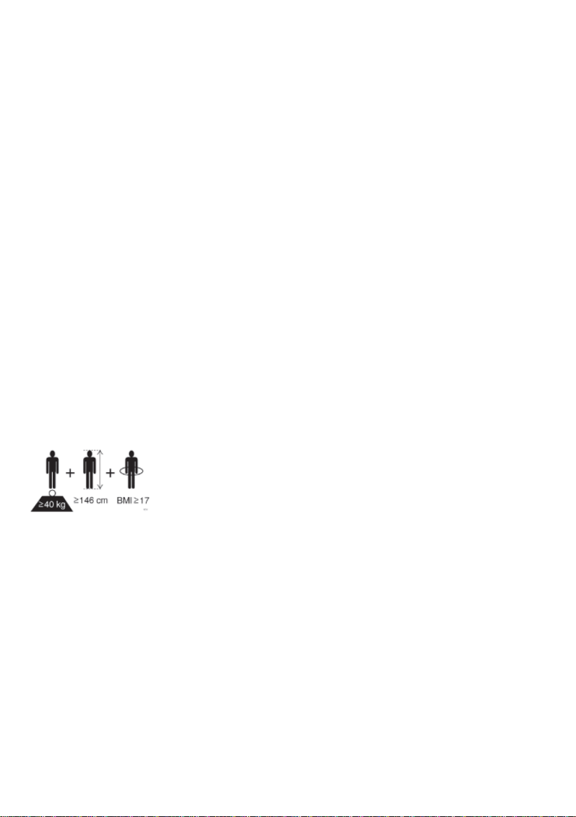
The nursing care bed is suitable for persons in need of care
(adults) who are at least 146 cm tall. The person's weight must
not exceed 280 kg and must be over 40 kg. The body mass index
(BMI = Weight of the person (kg) / (body size of the person (m)2)
must be greater than or equal to 17.
adilec 280 is a special bed for the optimal care of severely overweight and obese patients.
It is suitable for use in therapy and rehabilitation as well as for care at home. With adilec
280, people with a body weight of up to 280 kg can be cared for comfortably. The con-
struction of adilec 280 has a highly stable ball guide system. The frame rigidity is addition-
ally reinforced and two double motors ensure reliable functioning. adilec 280 offers a high
level of lying comfort to frail persons suffering from diseases and in the need of care as
well as to people with disabilities, while at the same time supporting an optimal care thank
to its easy operation.
–adilec 280 is not suitable for hospital use.
–is not suitable for the patient transport. The beds must be only moved for cleaning
purposes inside the patient’s room or to allow access to the patient.
–is suitable for persons in need of care (adults) with a body height of 146 cm or
more. The person's weight must not exceed 280 kg and must be over 40 kg. The
body mass index (BMI) must be greater than or equal to 17.

–under certain circumstances adilec 280 can be used (if necessary) for medical pur-
poses with other electric medical equipment (e.g. suction devices, ultrasonic hu-
midifier, food systems, anti-bedsore systems, oxygen concentrators and similar de-
vices). In this event, deactivate all bed functions for the duration of the application
via the integrated locking function.
Attention: The bed has no special connection options for a potential equalisation. Electri-
cal medical devices connected to the patient´s intravascular or intracardiac system must
not be used. The operator of the medical products has to ensure that the combination of
the equipment meets the requirements of EN 60601-1.
1.2 Definition of person groups
Operator
Operators (e.g. medical supply stores, specialist dealers, facilities and budget holders) in-
clude any natural or legal person who uses the beds or has the bed used for medical pur-
poses. The briefing on the use of the product shall generally be conducted by the operator.
User
Users are persons whose training, experience or briefing on the product allows them to
operate the nursing care bed or carry out works on it. The user is able to recognize possible
hazards and/or to avoid them and to assess the health condition of the patient.
Patient/resident
Persons in need of care as well as disabled and fragile people who are lying in the nursing
care bed.
Qualified personnel
Employees of the operator are referred to as qualified personnel. They are entitled to
deliver the nursing care bed, assemble, disassemble and transport it, on the basis of their
training or instructions. Besides knowing how to operate, assemble and disassemble the
nursing care bed, these persons must be instructed according to the guidelines concerning
the cleaning and disinfection of the nursing care bed.

6
1.3 Safety instructions
The intended use/operation of all moving parts is as important for the safety of the per-
sons in need of care as well as for the relatives and the caregivers/nursing staff to avoid
potentially dangerous situations. This requires the correct assembly and operation of the
bed. The individual physique of the person in need of care as well as type and the extent
of their disability must be taken into account by all means when operating the bed.
Avoid dangers, accidental motor adjustments and incorrect operation by using the disa-
bling function. When the operator, e.g. the nursing staff/caregivers or the care providing
relative leaves the room, the entire operating functions of the bed should be disabled via
the hand control. This is achieved by operating the key of the hand control. First, lower
the lying surface to the lowest position and activate the lock function with a twist of the
keylock (located in the key lock on the backside). Remove the key and check the function
of the hand control for safety reasons. Make sure that it is indeed locked.
These recommendations apply particularly:
–if the person in need of care cannot operate the hand control safely due to certain
disabilities;
–if the person in need of care or the caregivers could be at risk due to those accidental
adjustments;
–if the side rails are in a raised position and there could be danger of trapping and
crushing,
–if children are unsupervised in the room with the bed.
Always make sure that the hand control (when not in use) is securely hooked in the sup-
port hook at the bed and cannot drop.
As a general rule, the bed should be operated by instructed nursing staff/caregivers, rela-
tives or in attendance of instructed persons.
When adjusting the lying surface, it is particularly important to ensure that no limbs are
placed within the adjustment range of the side rails. If the side rails are adjusted, pay
attention to the correct lying position of the person in need of care.
Prior to making any electrical adjustment, it should, as a general rule, be made sure that
no limbs are positioned in the adjustment range between the chassis and the head or foot
part, especially that there are no persons/animals in the area between the floor and the
raised lying surface. Danger of being crushed is particularly high in these areas.

7
The permitted person’s weight depends on the total weight of the equipment that has
been mounted to the bed (mattresses and other electronic medical devices). Please refer
to the type plate on the frame of the lying surface for the respective max. capacity.
Service and maintenance must not be carried out while the nursing care bed is being used
by a patient.
The nursing care bed may only be used for the care and positioning of people. The adjust-
ment options on the head and foot sides serve exclusively for the changeable positioning
of the respective body area of a patient. The care bed may only be used for its intended
purpose and may not be misused or used improperly.
The patient must be immediately removed from the bed in case of malfunction or equip-
ment failure. Use of incompatible side rails may result in entrapment of extremities. To
deactivate the nursing care bed and safely end operation of the bed, remove the mains
plug from the socket.
1.4 Service life / warranty
This nursing care bed was developed, designed and manufactured for safe operation over
a long period of time. With proper operation and use, this nursing care bed typically has
an expected service life of 15 to 20 years in the institutional area. The service life depends
on operating conditions and frequency.
Attention:
Unauthorised technical changes to the product voids all warranty claims.
This product is not approved for the North American market, particularly not for the
United States of America (USA). Distribution and use of the nursing care bed in these
markets, including through third parties, is prohibited by the manufacturer.
Bock safety note
When the user, e.g. the nursing staff or caring relatives, leaves the room, the lying surface
should be moved to the lowest position in order to minimise the risk of injury if the patient
falls out.
When the user, e.g. the nursing staff or caring relatives, leaves the room, the complete operat-
ing functions of the nursing bed should be locked using the key of the hand control.

8
1.5 Requirements for the installation location
The company Hermann Bock GmbH is not liable for damages which might arise from the
daily usage on the floor.
To avoid floor indentations, floor should correspond to the recommendations of the FEB
- Fachverband der Hersteller elastischer Bodenbeläge e.V. (Association of Elastic Floor
Coverings Manufacturers). To do this, the technical information FEB No. 3 can be refer-
enced.
1.6 Type plate
Each nursing care bed is marked with an individual type and a general type plate. You will
find the type plates on the longitudinal frames of the lying surface (inside or outside, de-
pending on the model).
Explanation of the symbols:
/
Conformity mark according to the Medical Device Regulation
Symbol for observance of the user manual
Within the European Union, this product must be
disposed via the separated municipal waste. Product may not
be disposed of via household waste.
Medical application part type B
Use only in dry rooms
Protection class II (double insulation, insulated for protection)
Hazard note from Bock
Simultaneous use of electrical appliances particularly in the vicinity of the operational bed may
result in small electromagnetic interactions of these electric devices, e.g. static noise in the ra-
dio. In such rare events, increase the distance of the devices. Do not use the same socket or
temporarily switch off the interference source and/or the disturbing or disturbed device.
If the bed should be operated with electrical medical equipment (contrary to its intended use),
the functions of the bed must first be disabled via the integrated lock function in the hand con-
trol for the duration of the application.

9
IPX4
Protection of electrical equipment against splashing water
Symbol for maximum patient weight
Symbol for safe working load
Maximales Bettengewicht inklusive sichere Arbeitslast
Symbol for the labelling of a medical device
Patient population
Follow the instructions appropriate for mattress size and
thickness
Address of the manufacturer
Anschrift des gesetzlichen Vertreters Schweiz
Anschrift des gesetzlichen Vertreters UK
MD
10
2General description of the functions
Construction design and function
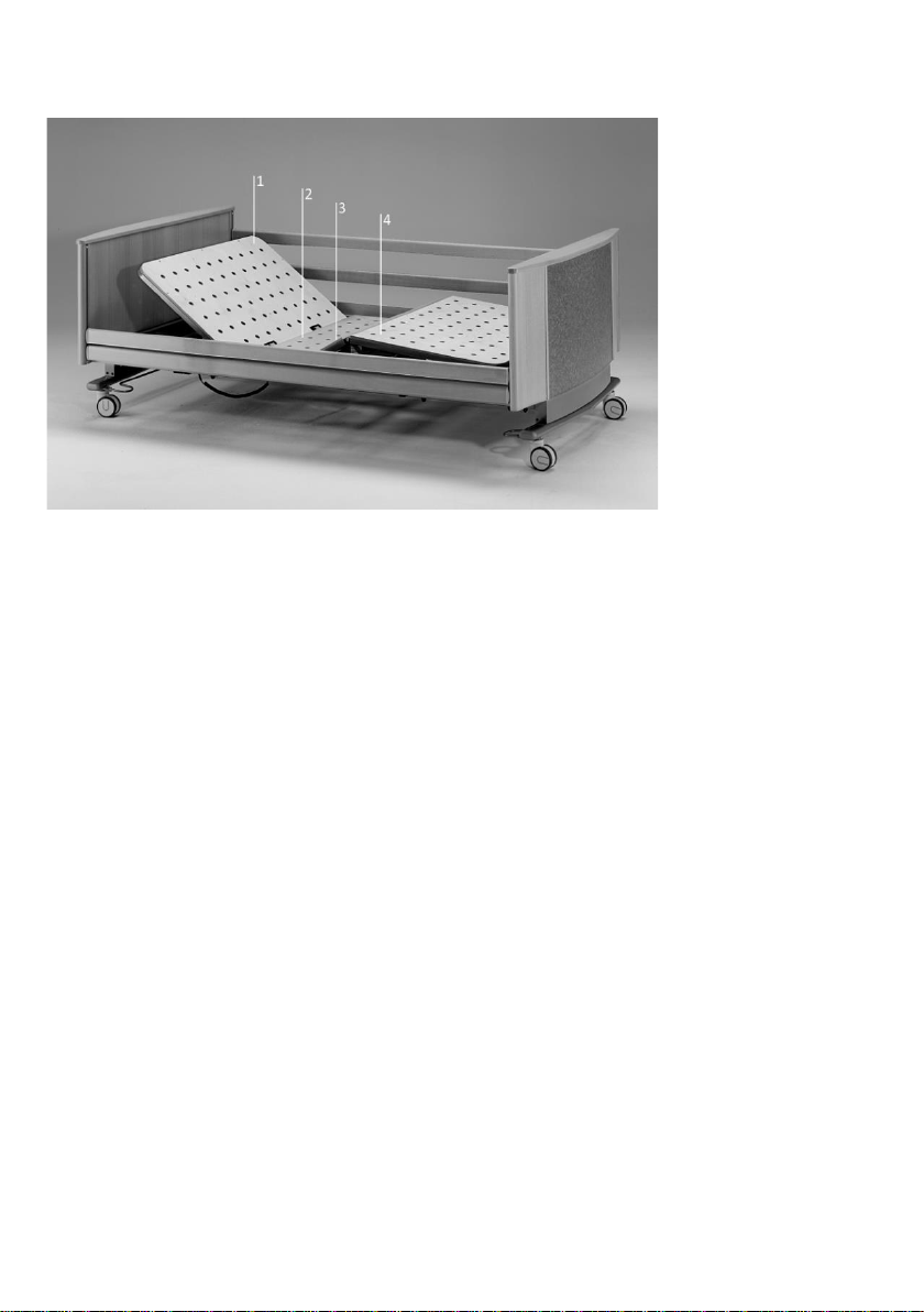
The lying surface with 4 function areas
The lying surface consists of a solid wood panel as standard and is divided into four func-
tional areas: back rest, fixed seat part, upper and lower leg rest.
The comprehensive lying surface frame is welded from a steel tube and stove-enamelled
with a PES-powder coating. The variable height adjustment of the lying surface is electric
and stepless. It is carried out by 24 V DC motors and controlled by the smooth keys of the
hand control. The back rest can be adjusted electrically. The leg part consists of a foot
support that is divided into two parts. With a touch of a button on the hand control, each
individual position can be adjusted continuously. The electronic hand control also allows
an automatic 3-way function to set a stretched leg elevation, the chest and the knee bend-
ing position. In the event of a power failure, the back and leg sections can be lowered
using a 9-volt battery.
The chassis
The height adjustment of the beds is carried out either via two height-adjustable adjusting
units, or via a base frame with single or double drive. The surface of the tubular steel
structure is stove-enamelled with a PES-powder coating.
1 Back rest
2 Seat part (fixed)
3 Upper leg rest
4 Lower leg rest
11
The side rails
Each nursing care bed is equipped with two integrated side rails on both sides at a special
safety height. The side rails can be lifted and lowered through a rail. The sliding pieces run
particularly smoothly and quietly with an impact damper, and the ends are fitted with
attractive looking caps. The side rail can be easily operated through an ergonomically de-
signed release button.
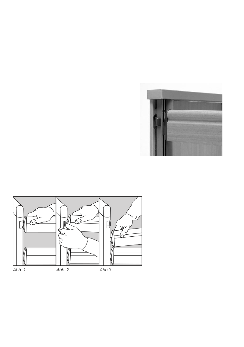
The operation of the continuous side rails
The release button for adjusting the continuous
side rails is located at the top of the inner sides of
the head and foot end panels directly next to the
metal guides for the side rail bars.
If the side rails are to be lowered, grasp the pro-
vided gripping groove of the upper side rail bar (Fig.
1), lift the side rail slightly and press the release
button on one side of the head or foot end panel
(Fig. 2). The side rail is released on the correspond-
ing side and can easily be lowered down to the stop
(Fig. 3). The side rail is now diagonal. To lower the other side as well, carry out the previ-
ously described steps on the opposite end. The side rail is now in a lowered position.
Please note: Be sure to raise the side rail slightly, and only then press the release but-
ton!
If the side rails are to be brought into the upper position as protection against falling
out, grasp the upper side rail bar in the middle of the gripping groove and pull the side
rail upwards until it audibly clicks into position at both ends. The side rail is now in its
raised position.

12
The side rails first and foremost serve as a fall prevention. In the case of very emaciated
persons in need of care, this protection is no longer sufficiently provided by the side rails
and additional protective measures must be taken, e.g. by adding fitted side-rail
bumpers (product accessory).
The distances between the continuous side rails must be less than 12 cm. When using
the continuous side rails, they must not remain in the diagonal position.
Hazard note from Bock
Use only original Bock side rails, which are available as accessories for every nursing care beds.
Use only technically flawless and non-damaged side rails with the permissible gap dimensions.
Make sure that the side rails are engaged securely.
Before installation of the side rail and each new use, inspect all mechanical parts on the bed
frame, and all parts of the side rails, and all parts which secure the side rails, for any possible
damages.
The operation of the side rail should be done with great care. Fingers can be quickly pinched
between the longitudinal pieces.

13
Fig. 1: Continuous wooden side rail, divided into two parts
Description
All dimensions in mm.
* Depending on the length of the lying surface
The single post at the head and foot end is optional.
The dimension in brackets is optional
Part numbers
Designation item no.
Continuous wood side rail
Two-part (Fig. 1)
Wooden side rail (set: 95 / 95 mm)
90843
Legend
Area Description
A Distance between the headboard and side rail
B Height 1 of the side rail
C Height 2 of side rail
D Width 1 of the side rail
E Distance between elements of the side rail sys-
tem
F Distance between the divided side rails
G Distance between lying surface and the top edge
of the side rail sytem
H Height of the top edge of the side rail system
above the mattress without compression
I Thickness of the mattress in accordance with in-
tended use
J Width 2 of the side rail
K Smallest distance between side rail system and
lying surface (or the panel, if present)
L Distance between the footboard and side rail

14
3Electric parts
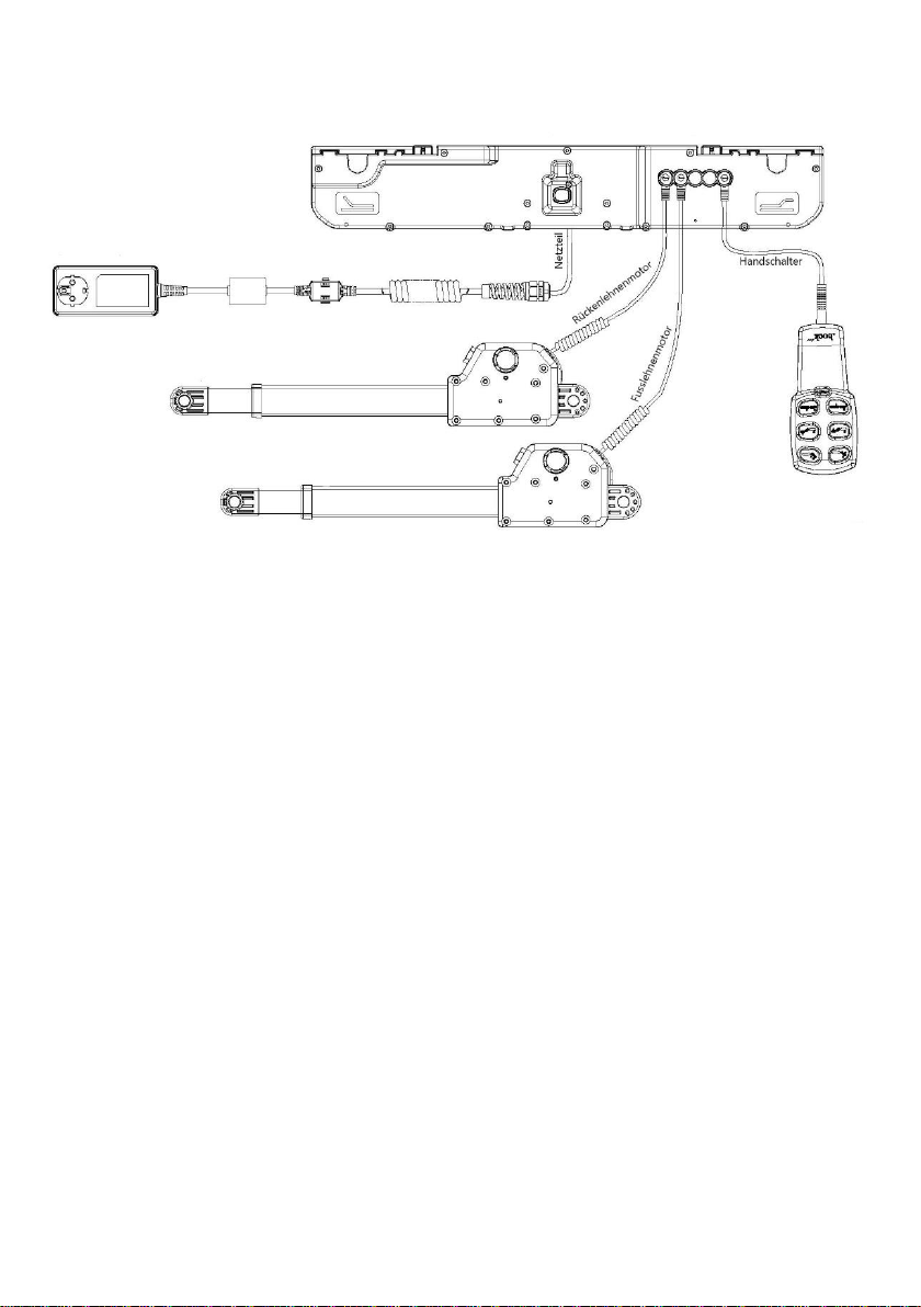
3.1 The drive unit
The drive unit consists of a double drive with two separate drive units for the electrically
movable adjustment of the backrest and leg rest. The level adjustment of the lifting frame
is adjusted via one or two individual drives (depending on the model). The level adjust-
ment drive is connected to the control box via a helical cable. The power supply unit con-
verts the input voltage to a safety extra-low voltage of max. 35V DC (direct current). This
safety extra-low voltage is used to operate the motors and the hand control. Cables are
double-insulated and the power supply unit has a primary fuse.
The internal emergency lowering is carried out via a
9 V block battery. Furthermore, power adjustment al-
lows for constant speed of the functions. Therefore,
the safety functions comply with protection class II,
and liquid ingress protection meets the standards of
protection code IPX4.
The maximum duty cycle is specified on the (type
plate) of the bed. For example, 10% duty cycle (2 min.
ON / 18 min. OFF) means that any electronic adjust-
ment can be performed for a max. of 2 minutes within
a timeframe of 20 minutes (protection against over-
heating).
If the maximum setting time of two minutes is exceeded e.g. by someone continuously
playing with the hand control which could lead to an overheating of the servomotors, the
thermal fuse immediately shuts off the power supply to the bed. After a cooling down
time of approx. one hour, the power supply will be automatically restored.
9 V block battery for emergency
lowering
Hazard note from Bock
The 9-volt batteries in the control unit should be checked once a year for their functionality and
replaced if necessary. In addition, regular visual inspections must be carried out.

15
3.2 Caution: Electric drive
The electrically operated nursing care bed enables persons in need of care to support
the recovery process psychologically and physically and at the same time relieve pain
through its various functions. Electrically operated beds that are medical products need
special care in regards to constant safety checks. This includes safety-conscious handling
of the bed, daily inspection of electrical equipment and proper cleaning and mainte-
nance.
To prevent damages to the cables, wiring should be conducted outside of the area in
which damages could be caused. Furthermore, avoid touching the sharp parts. To prevent
injury through an electric shock, avoid the possibilities of too high contact voltages. These
circumstances may especially be the case if the power cable is damaged, if inadmissible
and excessive leakage currents exist, or if liquid was spilled into the motor housing, e.g.
during improper cleaning. This damage can cause malfunction of the control unit, which
could result in unintended movements of single bed elements, posing a risk of injury for
the operator and the person in need of care.
Hazard note from Bock
All drive components must not be opened!
Troubleshooting or exchanging single electrical components may only be performed by specifi-
cally authorised professionals.
Hazard note from Bock
The motors comply with splash water protection IPX4. The cables must not be crushed. Adjust-
ment of moving parts may only be used for the intended use. Hermann Bock GmbH assumes no
liability for unauthorized technical changes.
Hazard note from Bock
Never attempt to repair electrical equipment yourself. In some cases there may be a risk of
life-threatening electric shock! Contact either the Customer Service department at Hermann
Bock GmbH or an authorised professional electrician to repair any defects in accordance with
all applicable VDE guidelines and safety requirements.

16
3.3 The drives with mains isolation
Hermann Bock GmbH equips the adilec nursing care bed with drive systems from the com-
pany Limoss.
The double drive for step-less adjustment of lying surfaces and the linear drive as single
drive for height adjustment of the lifting frames each consist of four main components.
▪Housing
▪Motor
▪Gearbox
▪Spindle with nut
The housing principle of the double drive and the single drive guarantees the permanent
function of all drive components. The special design principle is based on two force-ab-
sorbing housing shells. Due to a detailed interior structure, the construction of the housing
interior creates an essential prerequisite for the precise integration of the drive technol-
ogy. Particularly simple assembly/disassembly and convenient installation space for the
emergency lowering battery and control electronics. A strong lateral slider distinguishes
the housing of the double drive.
3.4 The external switch mode power supply SMPS
The drive has a primary fuse in the power supply unit and an emergency lowering function.
The SMPS adapter (Switch-Mode-Power-Supply) is an electronic transformer, which only
warms up a minimally under load and is equipped with electronic performance monitor-
ing. The result is a constant voltage up to the maximum load (no loss of speed) and a high
level of protection against overloading. The external transformer ensures safety right from
the socket because it converts the mains voltage directly into the safety low-voltage which
is used to actuate the nursing care bed. It is connected to the mains supply cable by means
of a coupling so that it can be replaced separately if it is defective.
The power supply unit complies with the European directives for electrical household ap-
pliances and therefore has a low energy consumption of max. 0.5 watts even in standby
mode and can be used internationally with variable input voltages from 100 V to 240 V.
Electromagnetic alternating fields are not measurable on the SMPS adapter and in opera-
tion still lower than mains isolation.
17
3.5 Connections of the double drive
3.6 Operating status display of the external SMPS unit
The SMPS (switch-mode power supply) unit has an LED that can indicate the following
operating states:
▪LED On: Ready for operation
▪LED Off: Discharged, not connected
▪LED Flashing: Error, thermal overload, or short circuit
After disconnecting the mains plug or the connection to the motor, the LED "glows" and
then turns off.

18
3.7 The hand control
The hand control is equipped with a built-in locking device, which allows the caregivers to
lock the hand control via a key completely or partially for its operation.
The lockable hand control, first-fault protected
The ergonomically shaped hand control allows users to control the bed’s basic
functions with either six or ten large, safe-to-operate buttons. Each button is
marked with an appropriate symbol. The position adjustment motors will con-
tinue to run as long as the corresponding button is pressed. A coiled cable offers
the necessary freedom of movement during use.
The rear-mounted hanger can be used to hang the hand control on the nursing care bed,
e.g. during cleaning or when providing patient care. To keep the hand control from getting
in the way, simply clip it anywhere on the bed frame.
Back rest upwards
Back rest downwards
Lower leg rest upwards
Lower leg rest downwards
Lying surface upwards
Lying surface downwards
Lighting on/off
Hazard note from Bock
Do not exceed the maximum duty cycle of 2 minutes. Observe a subsequent break of at
least 18 minutes by all means.

19
Hand control - lock functions
The hand control comes with an integrated locking mechanism that can be activated and
deactivated with the corresponding key. To lock the entire electrical function, insert the
key in the keylock on the backside and turn the lock function on or off with a correspond-
ing twist of the key.
Locking device 1 (standard)

20
4Assembly and operation
4.1 Technical data
Technical data
adilec 280
Lying surface dimension: cm
100 / 120 x 200
Outer dimension: cm
116 / 136 x 223
Safe working load: kg
315
Max. weight of person: kg
280
Height adjustment: cm
40 - 81
Max. adjustment angle to horizontal:
- Back rest
70°
- Lower leg rest
20°
- Trendelenburg position
no
Selection options for side rails:
- Continuous wooden side rail
•
Lift space clearance: cm
15
Sound level: dB(A)
<65
Weights:
Total incl. continuous wooden side rail: kg
210
Continuous wooden side rail: kg/set
12.5
Metal lifting column: kg
34
Wooden end panel: kg
22
Lying surface: kg
81
Electric data
Motor
Input voltage: V
230
Frequency: Hz
50
max. power consump-
tion: A
2
All parts and Information are subject to a constant further development and therefore may differ
from the mentioned data.
Table of contents
Other BOCK Medical Equipment manuals


Popular Medical Equipment manuals by other brands


Otto Bock
Otto Bock ROBO-WRIST Instructions for use

Heart Sure
Heart Sure A380 Instruction manual & warranty information

HYPERICE
HYPERICE Normatec 3 Let's get started

Rosie Connectivity Solutions
Rosie Connectivity Solutions Scan Assembly guide

Söring
Söring Arco-3000 Service manual

Foxwell
Foxwell NT500 user guide