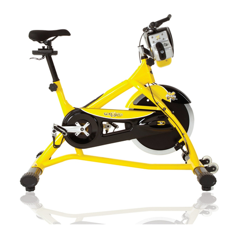
BODY BIKE SUPREME User manual

01
BODY BIKE INDOOR CYCLING APP
INSTRUCTIONS
BODY BIKE®INDOOR CYCLE
BODY BIKE®SUPREME
ENGLISH

Equipment required 2
Introduction 3
Specifications 4
General information 4
Warranty 5-6
Assembly
Unpacking 8
Bottom frame 8-9
Handlebar 10
Bottle holder 10
Saddle 11
Pedals 11-12
Maintenance
Cleaning 14
Sidewards play in posts 15
Cleaning the posts 16
Adjustment handles 16-17
Replacing the brake block 17-18
Poly-V belt 19
Removal of side covers 20
Support
Trouble-shooter 21-23
Online information 24
Index 25
Unpacking
Drill bit
Drill
Bottom frame
13 mm wrench
Saddle
14 mm wrench
Pedals
15mm pedal wrench
Grease
Cleaning
Tissue paper or cloth
Spray bottle with water
Soap (only washing-up liquid)
Vaseline oil
Post cleaning
Cloth
Vaseline oil
Sidewards play in posts
A coin
3mm Allen wrench
32mm wrench
Adjustment handle
5mm Allen Wrench
Screwdriver
Steel brush
Grease
Brush
Brake block
A coin
8 mm wrench
Poly-V belt
A coin
10 mm Allen wrench
19 mm wrench
Measuring device
Side covers
A coin
3,4 and 8 mm Allen wrenches
13 mm wrench
EQUIPMENT REQUIREDTABLE OF CONTENTS
02

This manual provides information on the assembly and
maintenance of the BODY BIKE® indoor cycle. The manual
is intended for the owners and service people responsible
for cleaning and maintenance.
Before assembling the cycle, please read the manual and
prepare the correct tools, see equipment required page
2. When assembling the cycle, we recommend that you
follow the manual step by step.
Maintaining the cycle is very important. In the manual you
will find clear instructions on how to maintain the cycle.
Over time it will be necessary to replace worn-out parts.
You will find a detailed description and exploded drawings
of BODY BIKE®’s spare parts on our website www.body-
bike.com. When ordering spare parts from the local BODY
BIKE® distributor, please refer to the item number (P/N
no.) in order to make sure you will receive the correct
spare part.
We recommend that you order original parts, accessories
and materials necessary for the maintenance of the cycle
at your local BODY BIKE® distributor.
For further information on accessories, please check our
website www.body-bike.com
INTRODUCTION
03

Manufacturer:
BODY BIKE® International A/S
Niels Bohrs Vej 2
DK-9900 Frederikshavn
Denmark
Phone: +45 9843 9696
Weight:
Assembled: 65 kilogram
Packed weight(5 cycles): 350kg
Length, Width, Height:
Assembled size:
105cm, 60cm, 100cm
Packed size (5 cycles):
120cm, 80cm, 114cm
Maximum user weight
150 kg (Please note that the
max. pedal load may be lower)
Materials
Cast iron
Stainless steel
Plastic (ABS) covers
High quality bearings
Frame: Robot-welded, powder
coated and hardened.
Patent held for:
Crank system
Wipe off the cycle after EVERY use.
ALWAYS loosen all handles
and release tension after use.
The rubber feet should always be adjusted to
ensure that the cycle is in level.
Every other year the rubber feet should be
replaced as the rubber hardens and becomes
unable to absorb the impact.
Tighten up the pedals every 14 days or every month to avoid
them getting loose or breaking off.
Pedals and adjustment handles should be changed once a year.
DO NOT perform stretch exercises on the cycle, pedals or up
against the cycle, except against the stretch area at the rear end
of the cycle.
DO NOT switch the front or seat post from one cycle to another.
DO NOT lift the cycle by the saddle.
SPECIFICATIONS
GENERAL INFORMATION
04

®
®
®
® SMART
®
®
®
WARRANTY
Figure 1
As information to our customers we hereby outline the warranty obligations applicable to BODY BIKE®Indoor Cycles.
The warranty comes into force the moment the unit leaves BODY BIKE International A/S.
To get an overview see figure 1.
05

Warranty for the Danish manufactured BODY
BIKE® Indoor Cycle:
A two-year warranty against manufacturing
defects, excluding normal wear and tear, is given
for the flywheel and pulley. A three-year warranty
is given on the crank and the pedal arms, and a five
year warranty is given against frame breakage.
Consumable items (such as the poly V-belt, brake
pad, handlebar rubber, adjustment handles, saddle
and pedals, etc.) which are subject to continuous
wear and tear, are not covered by a warranty.
There is currently no warranty applying to the
pedals.
The warranty only applies to cycles equipped with
original BODY BIKE® spare parts. All warranties are
cancelled if the cycle has been modified or in any
way not used as intended.
PLEASE NOTE
ALWAYS RELEASE TENSION AFTER USE
WARRANTY
!
In order for the warranty to be sustained, all instructions
in the respective manuals have to be followed.
This particularly relates to:
• Replacement of rubber feet on the bottom frames
once a year
• Replacement of pedals once a year and tightening of
these
• General cleaning of the bikes after use with correct
materials
• Lubrication of the adjustment handles every 3
months
• Original spare parts must be used on the bike
Warranty repairs are to be carried out by BODY BIKE
International A/S in Denmark.
At the expense of BODY BIKE International A/S.
Related freight costs are held by the customer.
Warranty spare parts are shipped ex. works.
06

ASSEMBLY
ASSEMBLY
Unpacking 8
Bottom frame 8
Handlebar 9
Bottle holder 9
Saddle 10
Pedals 10
07

A fixing tool can be bought at BODY BIKE® International
A/S to ease the mounting of the bottom frame.
1) Arrange the bottom frames parallel on the floor next
to the cycle with the correct mounting distance between
them, see figure 3. On the front bottom frame, the
transport wheels should point forward.
2) Take hold of the front post and seat post and lift the
cycle onto the bottom frames, see figure3. Ensure that
the holes in the frame match the holes in the bottom
frames.
3) Put on the spring lock washer and the cap nut and
tighten by using a 13 mm wrench, see figure 4.
4) Unscrew the rubber feet a little. Place the cycle in the
correct position. Turn them up and down until the cycle
stands properly and it is in level.
UNPACKING BOTTOM FRAME
1) Open the top of the box.
2) Remove all the unmounted parts.
3) Flatten the box on the floor next to the pallet.
4) Loosen the four screws mounting the first
cycle to the pallet. See figure 2.
5) Lift the cycle off the pallet and place it on
the flattened box to spare your floor from
getting marks.
Remove all four screws
Figure 2
PLEASE NOTE
Do not overtighten the nuts.
Max 12 Nm
!
08

ASSEMBLY
BOTTOM FRAME
Figure 3
Figure 4
CAP NUT
WASHER
Front bottom
frame with
wheels pointing
forward
Tighten with
no more than
12 Nm
Back bottom
frame
LIFTING SPOTS. Be sure that the saddle
and handlebar are locked before lifting
09

HANDLEBAR BOTTLE HOLDER
1) Place the handlebar on top of the front post.
2) Screw an adjustment handle (size 32mm)
clockwise into the socket from underneath
the post, see figure 5. Fix the handlebar
completely to the front post by tightening
the adjustment screw on the right side of the
handlebar.
Mount the bottle holder at the top of the handlebar, see
figure 6. Insert the two rubber rings so the bottle holder
is firmly fixed.
Figure 6
Add 2 x on each
side
WASHER
Figure 5
010

SADDLE PEDALS
ASSEMBLY
ONLY RELAVENT IF THE SADDLE IS NOT ALREADY
INSTALLED.
1) Place the saddle in the track on the seat post.
2) Secure the saddle with the remaining adjustment
handle, see figure 7.
To fasten the saddle to the adaptor and adjust the tilt
of the saddle, use a 14 mm wrench on the bolt marked
with an A on figure 7.
1) Place the right pedal arm with the socket
pointing upwards, see figure 8 .
2) Put maximum resistance on the brake, so the
pedalarm is unable to rotate, see figure 9
PLEASE NOTE
The pedals are marked with R for Right and L
for Left side.
The pedals should always be screwed on in
the direction of the handlebar, see figure 10
and 11.
Make sure that the hole in the pedal arm is
greased when mounting the pedal.
Start mounting the pedal by hand as tools will
tighten the pedal at a wrong angle.
3) After tightening by hand, use a 15mm pedal
wrench to tighten the pedal completely (45Nm).
WASHER
Figure 7
A
!
011

PEDALS
Figure 8
Figure 9
Figure 10
Figure 11
Always screw
on in the
direction
towards the
handlebar
Increase the resistance of
the brake, before installing
the pedals.
012

MAINTENANCE
MAINTENANCE
Cleaning 12
Sidewards play in posts 12
Cleaning the posts 13
Adjustment handles 13
Replacing the brake block 14
Poly-V belt 14
Removal of side covers 15
013

CLEANING
After each workout, wipe the cycle down with
tissue paper.
If the cycle is covered in sweat or dirt, use water
in a spray bottle and if necessary a tissue with
some washing-up liquid.
Remember handlebar and saddle.
To make the cycle look its best, use a cloth with a
little vaseline oil on all parts except the handlebar
and saddle.
Vacuum clean the bike inside when necessary to
prevent dust from gathering on the flywheel. If
dirt has already gathered on the flywheel edge,
use a piece of rough felt to sand it down.
At an annual service check, remove the right side
cover and make sure that the small hole by the
front bottom frame is not blocked and allows
water and sweat to exit the frame, see figure 12.
Also check that the ribs on the poly-v belt and
pulley are clean. To remove the side cover go to
page 20.
PLEASE NOTE
NEVER use alcohol or chemicals
Figure 12
Small drainage
hole.
Right side
cover has
been removed
!
014

MAINTENANCE
SIDEWARDS PLAY IN POSTS
Front post
1) Remove the service hatch. See figure 17.
Remove the right side cover by loosening the 8
bolts by using a 3 mm Allen wrench.
2) Adjust the 5x6mm pinion screw, marked S1 by
using a 2.5 mm Allen wrench, see figure 13.
Seat post
1) Remove the seat post
2) Remove the handle, the 32 mm nut and the
brass piston with a 32 mm wrench.
3) Remount the seat post
4) Carefully lift up the top cover as shown on figure
14. Adjust the right hand side screw marked S2 with
a 2.5 mm Allen wrench.
5) Push the top cover back in place.
6) Remove the seat post and remount the brass
piston, 32 mm nut and the handle
7) Remount the seat post
Figure 13
S1
S2
Figure 14
PLEASE NOTE
The adjustment has
to be very subtle in
order for the post
still to be able to
move up and down.
!
015

ADJUSTMENT HANDLESCLEANING THE POSTS
Every other week the posts need cleaning to
protect them from sweat etc.
Pull out the seat post and the front post and wipe
them clean with an oily cloth, see figure 15. Use
vaseline oil.
PLEASE NOTE
The posts should be cleaned every other
week to keep them in good condition
Figure 15
CreatedbyOlenaPanasovska
fromtheNounProject
1x oily cloth
Every 3 months the handles need cleaning and grease to
protect the parts from sweat, dust, dirt and water.
1) Remove the adjustment handle and disassemble the
handle completely into a screw, a spring, a handlegrip,
a main screw and a brass washer, see figure 16. Do this
with both the horizontal and vertical adjustment handle.
You don’t need to remove the 32mm nut.
Release
Figure 16
Vertical
adjustment
Herizontal
adjustment Washer
Screw Main
screw
Spring
Hand grip
32mm nut
!
016

REPLACING THE BRAKE BLOCK
MAINTENANCE
2) Clean all the parts thoroughly one by one using a
steel brush. If the residue is extreme, a sharp object
can be used, for example a screwdriver.
3) Lubricate the internal parts with grease before
reassembling the handle. Remember to lubricate
inside the handlegrip as well.
4) Reassemble the handle by inserting the main
screw in the handlegrip.
5) The spring is inserted into the top of the handle
and fixed in place with the remaining screw.
6) Tighten with a 5mm Allen wrench.
7) Add grease to the main screw before mounting it
on the cycle.
PLEASE NOTE
Never use a tool when tightening
the adjustment handle on the cycle.
By pulling the handle it can be
turned freely.
!
The Kevlar® pad on the BODY BIKE® Synthetic
Brake has an expected durability of a minimum of
1500 hours, so eventually the brake pad will be worn.
To ensure that the brake pad is correctly mounted,
it has been pre-fitted to the block, and it is only
possible to purchase the complete brake block.
Inspect the Kevlar brake pad after the first month
and hereafter every 3rd month. The Kevlar® brake
pad should be replaced before it is worn through and
reveal the black rubber.
Figure 17
Service hatch
Lock
Lock
Lock
017

1) Remove both service hatches by loosening
the locks with a coin, see figure 17.
2) Release tension completely on the brake.
3) Remove the two screws holding the brake
block to the frame by using an 8 mm wrench,
see figure 18
4) Take the new brake block and fasten it to
the frame by tightening the screw closest to
the brake block. Then place the block in the
correct position under the brake (see figure
19).
5) Fasten the remaining screw furthest
away from the block, and then make sure
that both screws are tightened properly, see
figure 20.
6) Grease should be applied to the cavity
on top of the brake block or to the top nut
on the brake to ensure a smooth interaction
between the two.
7) Remount both service hatches.
Figure 18
Figure 19
Figure 20
Remove
screws
Install and
twist
Reinstall the
last screw
REPLACING THE BRAKE BLOCK
018

MAINTENANCE
POLY-V BELT
If the belt does not catch hold of the flywheel, it is time for
it to be tightened.
1) Remove the service hatch on both sides of the cycle by
loosening the three locks with a coin, see figure 17.
2) Loosen the bolts (1) on both sides of the cycle with a 19
mm wrench, see figure 21.
3) Loosen the nuts (2) on the counter bolt on both sides
of the cycle using a 10 mm wrench, see figure 21.
4) Use a 10 mm wrench to tighten the counter bolts (3).
On the right side, the tool should be pulled downwards
and on the left side upwards to tighten.
5) The belt should be tightened to approximately 125
kg/229 Hz. To measure this, a special device can be
bought at your local BODY BIKE® distributor.
6) Tighten the counter bolt (2) on both sides of the cycle
again.
7) And tighten the bolt(1) again on both sides of the cycle.
8) Close the cycle by fastening the two hatches again.
PLEASE NOTE
The belt should be evenly tightened on both
sides.
The flywheel should be parallel with the long
main side member.
!
1
2
3
Figure 21
019

REMOVAL OF SIDE COVERS
The side covers can be removed e.g. if the belt needs to
be changed.
1) Dismount the right pedal arm with an 8mm Allen
wrench. See figure 22. Remove hatch. See figure 17.
2) Loosen all the screws holding the side cover with a 3
and 4 mm Allen wrench and remove them. See figure 23.
3) Dismount the top nut and washer on the bottom frame
on the right side of the cycle both in front and back with a
13 mm wrench. See figure 24.
4) Screw the bolts down in order for the side covers to
slide past them. See figure 24.
5) Remove the side cover.
Figure 22
Figure 23
Figure 24
020
Table of contents
Other BODY BIKE Exercise Bike manuals

BODY BIKE
BODY BIKE Basic User manual

BODY BIKE
BODY BIKE Classic Supreme User manual

BODY BIKE
BODY BIKE Basic User manual

BODY BIKE
BODY BIKE Indoor Cycle User manual

BODY BIKE
BODY BIKE SMART+ User manual

BODY BIKE
BODY BIKE Indoor Cycle User manual

BODY BIKE
BODY BIKE CONNECT User manual

BODY BIKE
BODY BIKE Classic User manual

BODY BIKE
BODY BIKE Smart Programming manual

BODY BIKE
BODY BIKE SMART+ User manual