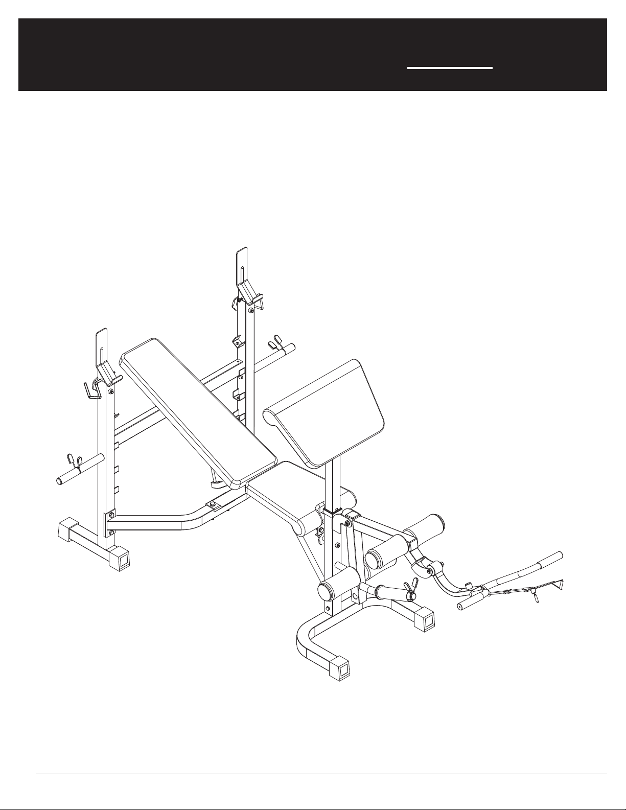
Body Flex Sports BODY CHAMP BCB 5860 User manual

OWNER’S MANUAL
* This item is for consumer use only and it is not meant for commercial use.
BCB 5860

This page intentionally left blank
General Information
BCB 5860 Page 1
Warranty
Body Flex Sports warrants your product for
a period of 1 year for the frame and 90 days
on all parts if the item is used for the intended
purpose, properly maintained and not used
commercially. Any alterations or incorrect
assembly of the product will void this warranty.
Proof of purchase must be presented for any
warranty validation (no exceptions). This
warranty applies to the original purchaser only
and is not transferable.
This warranty does not cover abuse or defects
caused during use, storage or assembly.
During the warranty period, Body Flex Sports
reserves the right to:
a). provide replacement parts to the
purchaser in an effort to repair the item.
b). repair the product returned to our
warehouse (at the purchaser’s cost).
c). replace the product if neither of the two
previously mentioned actions effect repair.
This warranty does not cover normal wear and
tear on upholstery.
Questions
If you have any questions concerning the
assembly of your item or if any parts are
missing, please DO NOT RETURN THE
ITEM TO THE STORE OR CONTACT THE
RETAILER. Our dedicated customer service
staff can help you with any questions you may
have regarding the assembly of this unit and
can also mail you replacement parts.
Customer Support
Customer Support is open 9:00 a.m. to 5:00
p.m. (Pacific Time) Monday through Friday.
Please contact us by any of the following
means.
Body Flex Sports, Inc.
21717 Ferrero Parkway, Walnut, CA 91789
Telephone: (888) 266 - 6789
Fax: (909) 598 - 6707
Email: info@bodyflexsports.com
Safety
Before you undertake any exercise program,
please be sure to consult with your doctor.
Frequent strenuous exercise should be
approved by your doctor and proper use
of your product is essential. Excessive or incorrect
training may result to health injuries. Please read
this manual carefully before commencing the
assembly of your product or starting to exercise.
• Please keep all children away from this item
when in use. Do not allow children to climb or
play on them when they are not in use.
• Supervise teenagers while they use this unit.
• For your own safety, always ensure that there
is at least 3 feet of free space in all directions
around your product while you are exercising.
• Regularly check to see that all nuts, bolts and
fittings are securely tightened. Periodically
check all moving parts for obvious signs of
wear or damage.
• Clean only with a damp cloth, do not use
solvent cleaners. If you are in any doubt, do
not use your product; contact CUSTOMER
SUPPORT.
• Before use, always ensure that your product
is positioned on a solid, flat surface. If
necessary, use a rubber mat underneath to
reduce the possibility of slipping.
•Always wear appropriate clothing and
footwear such as training shoes when
exercising. Do not wear loose clothing that
could become caught in moving parts during
exercise.
• Do not use this unit if it is not functioning
properly or if it is not fully assembled.
• Do not use this unit for commercial purposes.
This unit is for home use only.
Storage and Use
Your product is intended for use in clean
dry conditions. You should avoid storage in
excessively cold or damp places as this may
lead to corrosion and other related problems.
Weight Limit
Your product is suitable for users weighing:
300 pounds or less.
• Before use, you must read and understand all
instructions & warnings stated in this Owner’s
Manual as well as posted on the equipment.
• It is the facility owner’s responsibility to properly
instruct users on the proper operation of the
equipment and to warn them of the potential
hazards.
• If at any time during exercise you feel faint, dizzy
or experience pain, stop and consult your
physician.
Assembling Tools
- Ruler with both metric and English measurements
- 2 x Adjustable Wrenches
- 1 x Philips (”Crosshead”) Screw Driver
•
Any adjustment devices that could interfere with
the user's movement on this unit should not be
left projecting.

WASHER
#56. Washer (M8)
[15 Pieces]
Pre-assembled [3 Pieces]
#55. Washer (M10)
[24 Pieces]
#39. Quick Clip
Tool
[2 Pieces]
#45. Hex Bolt (M10x140 mm)
[1 Piece]
#46. Hex Bolt (M10x85 mm)
[4 Pieces]
#47. Hex Bolt (M10x75 mm)
[2 Pieces]
#48. Hex Bolt (M10x70 mm)
[2 Pieces]
#49. Hex Bolt (M10x65 mm)
[1 Piece]
#50. Hex Bolt (M10x25 mm)
[2 Pieces]
#41. Right Safety Hook
#51. Hex Bolt (M8x40 mm)
[8 Pieces]
#42. Left Safety Hook
[1 Piece] [1 Piece] [3 Pieces]
NUT
#54. Nylon Nut (M8)
[2 Pieces]
Pre-assembled
#53. Nylon Nut (M10)
[12 Pieces]
OTHERS
#52. Hex Bolt (M8x20 mm)
[7 Pieces]
Pre-assembled [3 Pieces]
#38. Knob Bolt (M10x60 mm)
#43. Pop-Pin (10x105 mm)
[1 Piece]
#44. Pop-Pin (8x70 mm)
[1 Piece]
[3 Pieces]
BCB 5860 Page 2
BOLT
Hardware List
The following hardware is used to assemble your unit. Please take a moment to familiarize yourself with these
items. Please note some of this hardware is already pre-assembled on the machine. Do not be alarmed if you
see parts on this page that are not included in your hardware packet.

Page 3
Parts Listing
The following parts list describes all of the parts illustrated on the
exploded diagram on the following page. Please note, most of
these parts are already pre-assembled on your unit.
# Description # Description
01 Right Upright 29 Square End Cap (50 mm)
02 Left Upright 30 Round End Cap
03 Rear Cross Tube 31 Round End Plug (25 mm)
04 Main Frame 32 Bumper
05 Front Upright 33 Adjustable Knob
06 Front Stabilizer 34 Square Spacer (60x50 mm)
07 Adjustable Upright Tube 35 Square Spacer (50x10 mm)
08 Leg Developer 36 AB Strap
09 Backrest Adjustment Tube
10 Backrest Supporting Tube
38 Knob Bolt (M10x60 mm)
11 Supporting Tube
39 Quick Clip
12 Foam Roller Tube
40 Spring Clip
13 Weight Plate Post
41 Right Safety Hook
14 Arm Curl Frame
42 Left Safety Hook
15 Olmypic Adapter
43 Pop-Pin (10x105 mm)
16 Arm Curl Bar
44 Pop-Pin (8x70 mm)
17 Reinforcement Plate
45 Hex Bolt (M10x140 mm)
18 Backrest Cushion Post
46 Hex Bolt (M10x85 mm)
19 Backrest Cushion
47 Hex Bolt (M10x75 mm)
20 Seat Cushion
48 Hex Bolt (M10x70 mm)
21 Arm Curl Cushion
49 Hex Bolt (M10x65 mm)
22 Foam Roller
50 Hex Bolt (M10x25 mm)
23 Foam Grip
51 Hex Bolt (M8x40 mm)
24 Round End Cap (25 mm)
52 Hex Bolt (M8x20 mm)
25 Rectangular End Cap (30x60 mm)
26 Square End Cap (45 mm)
54 Nylon Nut (M8)
27 Square End Cap (25 mm)
55 Washer (M10)
28 Square End Cap (60 mm)
56 Washer (M8)
BCB 5860
57 Square Spacer (50x45 mm)
53 Nylon Nut (M10)

Page 4
The following diagram is provided to help you familiarize yourself with the parts and
hardware that will be used during the assembly process. Please note that not all of the
parts and hardware you see here will be used while you are assembling the machine
because some of these items are already pre-installed. Please continue to the next
page to begin the assembly process and use this page only as a reference guide for
parts and hardware.
Exploded Diagram
BCB 5860

Page 5
Hardware Required
A s s e m b l y S t e p 1
(REAR)
(FRONT)
WASHER
#55. Washer (M10)
[8 Pieces]
#46. Hex Bolt (M10x85 mm)
[4 Pieces]
NUT
#53. Nylon Nut (M10)
[4 Pieces]
BOLT
A). With the help of an assistant, stand both Right
Upright (#01) and Left Upright (#02) on level flooring
as illustrated.
Attach the Rear Cross Tube (#03) to the Right/Left
Uprights (#01/#02) and secure together by inserting
from the rear side as illustrated -- on each side -- two
Hex Bolts (#46) through two Washers (#55) followed
by an additional two Washers (#55) and two Nylon
Nuts (#53).
B. Attach/insert the Backrest Adjustment Tube (#09)
onto the same bracket notch settings*** on both Right
Upright (#01) and Left Upright (#02).
***NOTE:
Please ensure any settings on left/right sides match
and are equal for alignment to avoid serious injury.
55
40
1 2 3 4
55
40
1 2 3 4
STEP3:
Assembly Instructions
A
B
BCB 5860

Page 6
A s s e m b l y S t e p 2
Hardware Required
WASHER
#56. Washer (M8)
[2 Pieces]
#41. Right Safety Hook
#42. Left Safety Hook
[1 Piece] [1 Piece]
NUT
#54. Nylon Nut (M8)
[2 Pieces]
OTHERS
BOLT
#52. Hex Bolt (M8x20 mm)
[2 Pieces]
#38. Knob Bolt (M10x60 mm)
[2 Pieces]
#39. Quick Clip
[2 Pieces]
(RIGHT)
(LEFT)
A). Remove the two Nylon Nuts (#54) pre-assembled on the Left/Right Safety Hooks (#42/#41). Set them aside nearby for
now.
On the left side, insert Left Safety Hook (#42) into the hole on top of left Adjustable Upright Tube (#07) as shown. Secure
using one Nylon Nut (#54) from the inner side.
Select the desired height*** for the Adjustable Upright Tube (#07) on the Left Upright (#02) and secure by screwing one
Knob Bolt (#38) through both the rear of Left Upright (#02) and Adjustable Upright Tube (#07).
Repeat this process on the right side with Right Safety Hook (#41), Right Upright (#01), and the other Adjustable Upright
Tube (#07).
***NOTE: Please ensure any settings on left/right sides match and are equal for alignment to avoid serious injury.
B). On the left side, insert the Weight Plate Post (#13) in through the side hole of Left Upright (#02). Secure from the inner
side using one Hex Bolt (#52) through one Washer (#56). Attach the Quick Clip (#39) to the outer side of Weight Plate Post
(#13).
Repeat this process on the right side with the other Weight Plate Post (#13) and Right Upright (#01).
A
B
55
40
1 2 3 4
55
40
1 2 3 4
STEP3:
Assembly Instructions
BCB 5860

A s s e m b l y S t e p 3
Hardware Required
Page 7
C
D
A). Remove the three Hex Bolts(#52) and three Washers (#56) pre-assembled on the Front Stabilizer (#06). Set them aside
nearby for now.
Attach the Front Upright (#05) to the Front Stabilizer (#06) and secure by using two Hex Bolts (#52) through two Washers
(#56) from each side as illustrated.
B). Attach the Front Upright (#05) to the Main Frame (#04) and secure by using two Hex Bolts (#50) through two Washers
(#55) and then two additional Washers (#55) and two Nylon Nuts (#53).
C). Attach the Main Frame (#04) over and onto the Rear Cross Tube (#03) by inserting two Hex Bolts (#48) through two
Washers (#55) and from the bottom one Reinforcement Plate (#17), an additional two Washers (#55), and two Nylon Nuts
(#53).
D). Attach the Supporting Tube (#11) to the bottom of Main Frame (#04) inserting downward one Hex Bolt (#49) through one
Washer (#55) followed by an additional Washer (#55) and one Nylon Nut (#53), and, to the back of Front Stabilizer (#06)
using one Hex Bolt (#52) through one Washer (#56) as shown in the diagram below.
WASHER
#56. Washer (M8)
[3 Pieces]
#55. Washer (M10)
[10 Pieces]
#48. Hex Bolt (M10x70 mm)
[2 Pieces]
#49. Hex Bolt (M10x65 mm)
[1 Piece]
#50. Hex Bolt (M10x25 mm)
[2 Pieces]
NUT
#53. Nylon Nut (M10)
[5 Pieces]
BOLT
#52. Hex Bolt (M8x20 mm)
[3 Pieces]
B
A
55
40 1 2 3 4
55
40 1 2 3 4
STEP3:
Assembly Instructions
BCB 5860
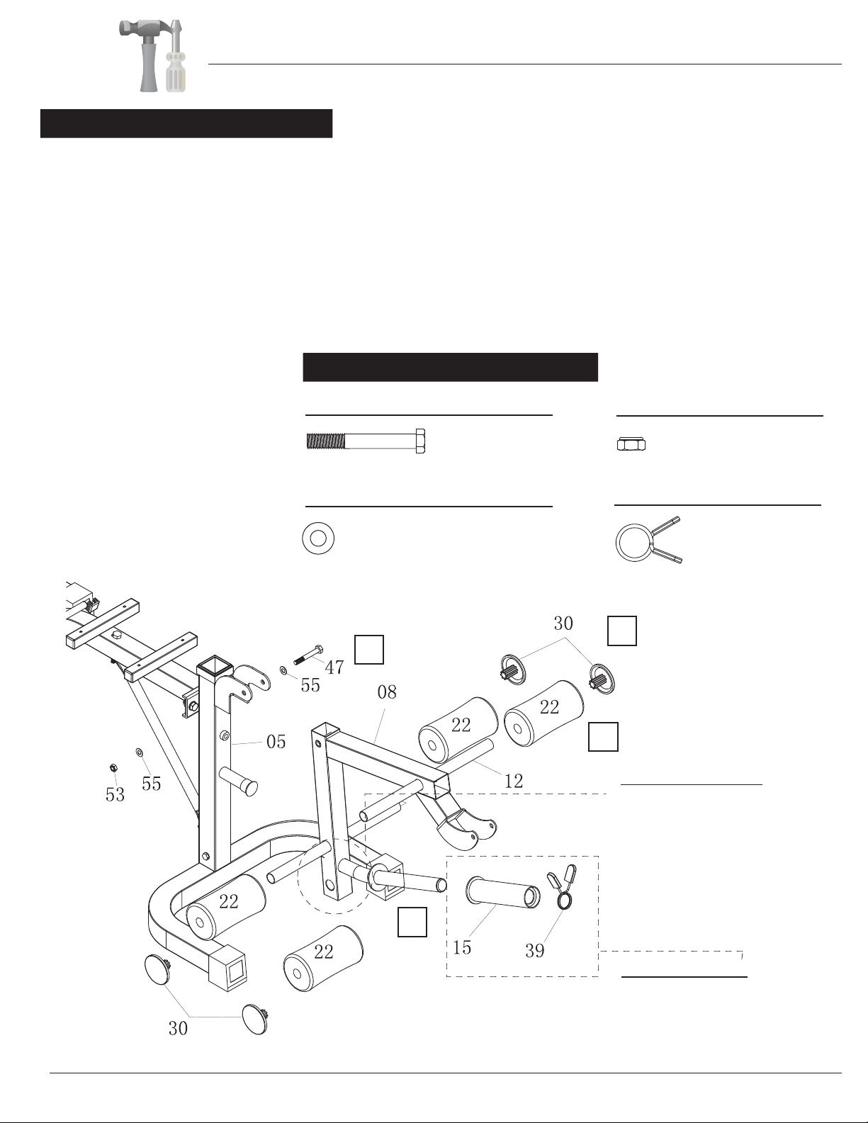
A s s e m b l y S t e p 4
Hardware Required
Page 8
OLYMPIC ADAPTER
If you intend to use Olympic plates,
slide the Olympic Adapter (#15)
over the standard plate post and
secure it with one
(#39).
Quick Clip
WASHER
#55. Washer (M10)
[2 Pieces] #39. Quick Clip
#47. Hex Bolt (M10x75 mm)
[1 Piece]
[1 Piece]
NUT
#53. Nylon Nut (M10)
[1 Piece]
OTHERS
BOLT
*FOAM ROLLERS
The Foam Roller Tube (#12)
can be placed through either
of these two holes depending
on your height. Simply
remove the Round End Cap
(#30) and one Foam Roller
(#22) from one end to reposition
the location of the Foam Roller
Tube (#12).
A). Attach the Leg Developer (#08) by aligning the holes to bracket of Front Upright (#05). Secure together using one Hex
Bolt (#47) through one Washer (#55) and an additional Washer (#55) followed by one Nylon Nut (#53) as illustrated.
B). Slide one Foam Roller (#22) onto one end of a Foam Roller Tube (#12). Next, slide the same Foam Roller Tube (#12)
through the lower hole of the Leg Developer (#08) as illustrated. Next, slide one more Foam Roller (#22) onto the other end
of the Foam Roller Tube (#12) (after it has been inserted through the lower hole).
Repeat this process with the other Foam Roller Tube (#12) and the two other Foam Rollers (#22) through the upper hole on
the Leg Developer (#08).
C). Attach the four Round End Caps (#30) on the outside of the four Foam Rollers (#22).
D). Attach the Olympic Adapter (#15) over the protruding tube of Leg Developer (#08) and secure using Quick Clip (#39)
as illustrated below.
55
40
55
40
1 2 3 4
STEP3:
Assembly Instructions
BCB 5860
A
B
C
D

A s s e m b l y S t e p 5 Hardware Required
Page 9
WASHER
#55. Washer (M10)
[2 Pieces]
#47. Hex Bolt (M10x75 mm)
[1 Piece]
NUT
#53. Nylon Nut (M10)
[1 Pieces]
BOLT
#44. Pop-Pin (8x70 mm)
[1 Piece]
OTHERS
A). Attach the Arm Curl Bar (#16) to the Leg Developer
(#08) by aligning the holes on bracket of Leg Developer
(#08) and securing them with one Hex Bolt (#47) through
one Washer (#55) followed by an additional Washer
(#55) and one Nylon Nut (#53) as illustrated.
B). For added versatility to your workouts, you may attach
the AB Strap (#36) to the bracket of Arm Curl Bar (#16)
using the Spring Clip (#40).
55
40 1 2 3 4
55
40 1 2 3 4
STEP3:
Assembly Instructions
BCB 5860
A
B
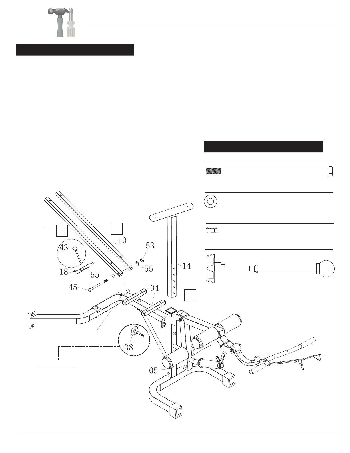
A s s e m b l y S t e p 6
Page 10
LOCK PIN
The
is used to place the
backrest into the
military position
quickly.
Pop-pin (#43)
Remove the Pop-pin
(#43) for all other
positions and insert it
into the hole on the
Main Frame (#04)
when it is not in use.
C
Hardware Required
A). With the help of an assistant, insert the two pegs on the sides of the Backrest Cushion Post (#18) into the two side holes
located on the inside of both Backrest Supporting Tubes (#10). While simultaneously holding these three pieces together,
align and slide the two holes on the bottom of the Backrest Supporting Tubes (#10) onto each side of the “welded rod” on
Main Frame (#04). Secure by inserting one Hex Bolt (#45) through one Washer (#55) followed by one additional Washer (#55)
and one Nylon Nut (#53). Please DO NOT OVER-TIGHTEN.
B). Insert the Arm Curl Frame (#14) into the Front Upright (#05) and secure it in place with one Knob Bolt (#38) as
illustrated below.
C). Insert the Pop-Pin (#43) into the hole on back of Main Frame (#04) for now. This Pop-Pin (#43) will allow you to adjust
seating positions for versatile workouts.
WASHER
#55. Washer (M10)
[2 Pieces]
#45. Hex Bolt (M10x140 mm)
[1 Piece]
NUT
#53. Nylon Nut (M10)
[1 Pieces]
OTHERS
#38. Knob Bolt
(M10x60 mm) [1 Piece]
#43. Pop-Pin (10x105 mm)
[1 Piece]
BOLT
KNOB BOLT
The Knob Bolt (#38) is used to adjust the height
of the Arm curl pad post. Simply unscrew the
Knob bolt (#38), reposition the height of the
Arm Curl Frame (#14) and then tighten the Knob
Bolt (#38).
A
B
“Welded Rod”
55
40
1 2 3 4
55
40
1 2 3 4
STEP3:
Assembly Instructions
BCB 5860
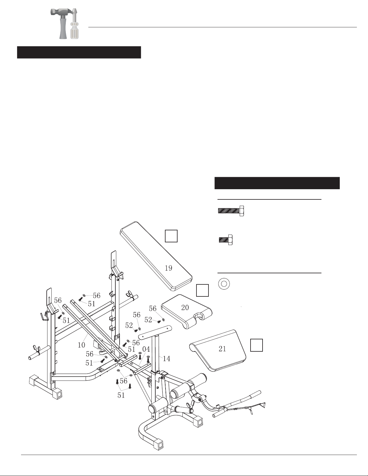
A s s e m b l y S t e p 7
Hardware Required
Page 11
A). Attach the Backrest Cushion (#19) gently onto the Backrest Supporting Tubes (#10) by inserting
and securing four Hex Bolts (#51) through four Washers (#56) from underneath the Backrest Cushion
(#19).
B). Attach the Seat Cushion (#20) to the two tubes on the Main Frame (#04) as shown in diagram.
Secure them together by inserting upward four Hex Bolts (#51) through four Washers (#56).
C). Attach the Arm Curl Cushion (#21) to the Arm Curl Frame (#14) using two Hex Bolts (#52) through
two Washers (#56).
The assembly process is now complete. However, for your own safety, please make sure to read this
entire Owner's Manual which includes safety instructions and warnings, as well as any safety/warning
labels affixed to the product before use.
WASHER
#56. Washer (M8)
[10 Pieces]
#51. Hex Bolt (M8x40 mm)
[8 Pieces]
BOLT
#52. Hex Bolt (M8x20 mm)
[2 Pieces]
55
40 1 2 3 4
55
40 1 2 3 4
STEP3:
Assembly Instructions
BCB 5860
A
B
C
FINAL CHECK (Before EACH use)
•Make sure all nuts and bolts are tightened (but do not over-tighten).
•Check for any loose parts and components and tighten prior to each use.
•Check to see if there are any tears or bends in the welding or metal prior to each use.
Do NOT use the product if you find any such tears or bends. Please contact our
Customer Service.
Be sure that all adjustment locking devices and safety devices are properly
located and fully engaged prior to use!
•
BCB 5860 Page 12

Before use, you must read and understand all instructions & warning stated in this Owner's Manual as well as
posted on the equipment.
Warm-Up Instructions
Groin Stretch
1. Sit with your knees flexed
and soles of feet together.
2. Hold your ankles and bend
at your hips (keep your
back straight) as you press
your knees toward the
floor with your elbows.
Hamstring Stretch
1. Sit with your left leg extended and bend your right
leg at the knee as you place the sole of your right foot
against the inner thigh of your extended leg.
2. Flex the foot of your extended leg (toes pointed
toward ceiling) and gently bend forward from your
hips; keep your back straight.
3. Reach your hands on your extended leg as far as pos-
sible and then switch legs and repeat.
Trunk Twister
1. Sit with your leg extended and
bend your right knee as you cross
your right leg over your left leg.
Your right foot should be flat on the
floor alongside your left knee.
2. Place your left arm on the outside
of your right leg and pull against
that leg while twisting your trunk
as far as possible to the right. Place
your right hand on the floor behind
your buttocks. Reverse leg posi-
tions and repeat.
Hip Stretch
1. Lie on your back and raise your right leg as you clasp both hands
under the back of the knee. Keep your left leg straight.
2. Gently pull your right leg toward your trunk without raising your
upper body. Switch leg positions and repeat.
The following flexibility exercises are provided to you as a means to prevent injury while you are exercising. A
proper warm-up routine decreases the chance of injuring your muscles while you are exercising. Please take the
time to do these flexibility exercises before and after each time you exercise.
Quadriceps Stretch
1. Stand on your left leg and hold onto
a support with your left hand.
2. Flex your right leg behind you, grasp
your ankle or foot with your right
hand and pull your foot toward your
buttocks. Keep your back straight
and right knee pointed down. Repeat
on the other leg.
BCB 5860 Page 13
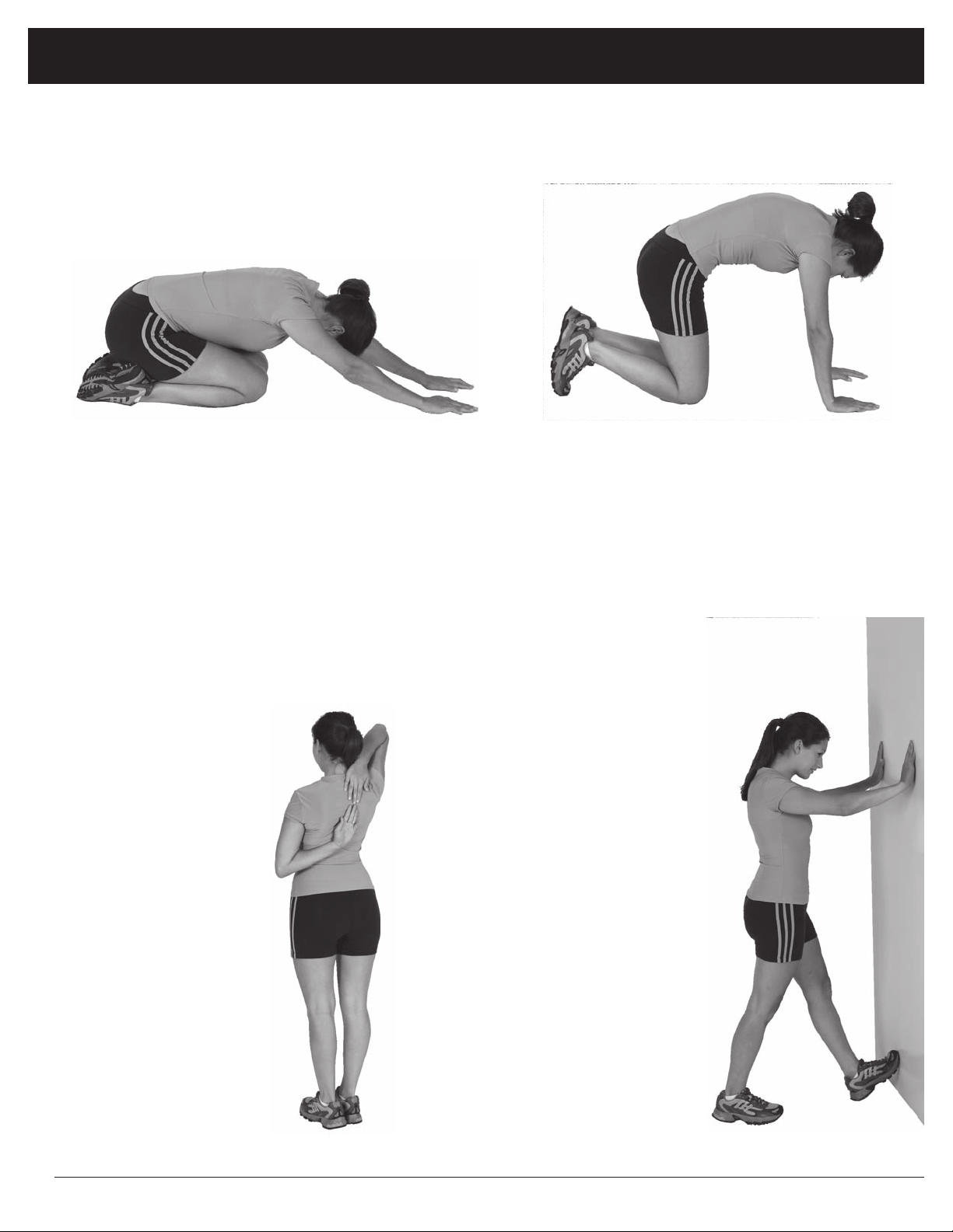
Trunk Flexion, Prone
1. Assume the depicted position on your hands and knees. Stretch your hands out in front of you and then slowly start to pull
them back in toward your body as you tuck your chin and arch your back upward.
2. Return to the starting position slowly.
Shoulder Stretch
1. Bring your right hand over
your right shoulder to the
upper back and bring your
left hand under your left
shoulder to the upper back.
2. Try to reach your finger-
tips. If you are not able to
reach your fingertips, use
a towel as an extension of
your hands and gently pull
one hand toward the other.
Reverse arm positions and
repeat.
Calf Stretch
1. Place both hands against
a wall to aid your balance.
Press the ball of your left foot
against the wall and keep the
heel of the same foot rested
on the floor (make sure your
left knee is bent).
2. Slowly start to straighten your
left knee and you will feel
the muscles in your left calf
stretch. Switch leg positions
and repeat.
Warm-Up Instructions
BCB 5860 Page 14

WARNING: SERIOUS INJURIES AND EVEN DEATH CAN OCCUR IF THE PROPER SAFETY PRECAUTIONS ARE NOT FOLLOWED.
The diagram below highlights and reviews many of the important Safety and Warning labels also found
on the unit. Please ensure any user of the unit familiarizes themselves with these Safety and Warning
guidelines before use.
PLEASE KEEP THESE INSTRUCTIONS FOR FUTURE USE & REFERENCE.
DO NOT DISCARD.
BCB 5860 Page 15

This page intentionally left blank

Proof of purchase
version: 12-21-2016
Model Number BCB 5860

Body Flex Sports, Inc. • 21717 Ferrero Parkway, Walnut, CA 91789 • Telephone: (888) 266 - 6789 • Email: info@bodyflexsports.com
Made in China
Table of contents
Other Body Flex Sports Elliptical Trainer manuals


