Body Flex Sports Rider BR 1830 User manual

BR 1830
OWNER’S MANUAL
EllipticalElliptical
* This item is for consumer use only and it is not meant for commercial use.

General Information
BR1830 Page 1
Warranty
Body Flex Sports warrants your product for
a period of 1 year for the frame and 90 days
on all parts if the item is used for the intended
purpose, properly maintained and not used
commercially. Any alterations or incorrect
assembly of the product will void this warranty.
Proof of purchase must be presented for any
warranty validation (no exceptions). This
warranty applies to the original purchaser only
and is not transferable.
This warranty does not cover abuse or defects
caused during use, storage or assembly.
During the warranty period, Body Flex Sports
reserves the right to:
a). provide replacement parts to the
purchaser in an effort to repair the item.
b). repair the product returned to our
warehouse (at the purchaser’s cost).
c). replace the product if neither of the two
previously mentioned actions effect repair.
This warranty does not cover normal wear and
tear on upholstery.
Questions
If you have any questions concerning the
assembly of your item or if any parts are
missing, please DO NOT RETURN THE
ITEM TO THE STORE OR CONTACT THE
RETAILER. Our dedicated customer service
staff can help you with any questions you may
have regarding the assembly of this unit and
can also mail you replacement parts.
Customer Support
Customer Support is open 9:00 a.m. to 5:00
p.m. (Pacific Time) Monday through Friday.
Please contact us by any of the following
means.
Body Flex Sports, Inc.
21717 Ferrero Parkway, Walnut, CA 91789
Telephone: (888) 266 - 6789
Fax: (909) 598 - 6707
Email: info@bodyflexsports.com
Safety
Before you undertake any exercise program,
please be sure to consult with your doctor.
Frequent strenuous exercise should be
approved by your doctor and proper use
of your product is essential. Please read
this manual carefully before commencing
the assembly of your product or starting to
exercise.
• Please keep all children away from this item
when in use. Do not allow children to climb or
play on them when they are not in use.
• Supervise teenagers while they use this unit.
• For your own safety, always ensure that there
is at least 3 feet of free space in all directions
around your product while you are exercising.
• Regularly check to see that all nuts, bolts and
fittings are securely tightened. Periodically
check all moving parts for obvious signs of
wear or damage.
• Clean only with a damp cloth, do not use
solvent cleaners. If you are in any doubt, do
not use your product; contact CUSTOMER
SUPPORT.
• Before use, always ensure that your product
is positioned on a solid, flat surface. If
necessary, use a rubber mat underneath to
reduce the possibility of slipping.
•Always wear appropriate clothing and
footwear such as training shoes when
exercising. Do not wear loose clothing that
could become caught in moving parts during
exercise.
• Do not use this unit if it is not functioning
properly or if it is not fully assembled.
• Do not use this unit for commercial purposes.
Storage and Use
Your product is intended for use in clean
dry conditions. You should avoid storage in
excessively cold or damp places as this may
lead to corrosion and other related problems.
Weight Limit
Your product is suitable for users weighing:
250 pounds or less.
• Before use, you must read and understand all
instructions & warnings stated in this Owner’s
Manual as well as posted on the equipment.
• It is the facility owner’s responsibility to properly
instruct users on the proper operation of the
equipment and to warn them of the potential
hazards.
• If at any time during exercise you feel faint, dizzy
or experience pain, stop and consult your
physician.
Assembling Tools
- Ruler with both metric and English measurements
- 2 x Adjustable Wrenches
- 1 x Philips (”Crosshead”) Screw Driver

Hardware & Tool List
BR1830 Page 2
The following parts list describes all of the parts illustrated on the
exploded diagram on the following page. Please note, most of
these parts are already pre-assembled on your unit.
Bolt
#105 Hex Bolt (M10x55 mm)
[2 Pieces]
#144 Hex Bolt (M10x45 mm)
[4 Pieces]
#146 Carriage Bolt (M10x57 mm)
[4 Pieces]
#157 Screw (M5x16 mm)
[2 Pieces]
Pre-assembled
#162 Right Pedal Hinge Bolt
[1 Piece]
#163 Left Pedal Hinge Bolt
[1 Piece]
Washer
#143 Arc Washer
( φ10x2.0xφ25xR28)
[4 Pieces]
#151 Spring Washer
( D12)
[2 Pieces]
#156 Washer
(φ10.2xφ25x2 mm)
[2 Pieces]
Pre-assembled
#164 Special Washer
(φ25xφ13x17x3.0)
[2 Pieces]
Nut
#145 Nylon Nut (M10)
[8 Pieces]
Pre-assembled [4 pieces]
#147 Nut (M10)
[4 Pieces]
#148 Left Nylon Nut
(B0.5x20 S19)
[1 Piece]
#149 Right Nylon Nut
(B0.5x20 S19)
[1 Piece]
Others
#112 Handlebar
Axle (φ16x410 mm)
[1 Piece]
#154 Lock Pin for Pedal Hinge
Bolt (φ3x16 mm)
[2 Pieces]
#142 Cap
(S16)
[8 Pieces]
#141 Cap
(S13)
[2 Pieces]
#117 Knob Bolt
(M8x36 mm)
[2 Pieces]
Tools
#168 Tool 1 (2-S17,S19)
[2 Pieces]
#169 Tool 2 (S8)
[1 Piece]
#170 Tool 3 (S13-14-15)
[1 Piece]
Pre-assembled

Parts Listing
The following parts list describes all of the parts illustrated on the
exploded diagram on the following page. Please note, most of
these parts are already pre-assembled on your unit.
BR1830 Page 3
# Descriptoin # Descriptoin
101 Main Frame 134 Chain (1/4"x204 Links)
102 Front Stabilizer 135 Friction Belt (1150L mm)
103 Rear Stabilizer 136 Tension Adjustment Knob
104L Left Coupler Bar 137 Square Inner Plug (口30 mm)
104R Right Coupler Bar 138 Screw (ST4.8x20 mm)
105 Hex Bolt (M10x55 mm) 139 Screw (ST4.8x45 mm)
106L Left Pedal Tube 140 Screw (ST4.8x16 mm)
106R Right Pedal Tube 141 Cap (S13)
107L Left Handle Bar 142 Cap (S16)
107R Right Handle Bar 143 Arc Washer (φ10x2.0xφ25xR28)
108L Left Chain Cover 144 Hex Bolt (M10x45 mm)
108R Right Chain Cover 145 Nylon Nut (M10)
109 Fan Wheel (φ503x55 mm) 146 Carriage Bolt (M10x57 mm)
110 Spring (φ1.8x32xφ10) 147 Nut (M10)
111 Pedal 148 Left Nylon Nut (B0.5x20 S19)
112 Handlebar Axle (φ16x410 mm) 149 Right Nylon Nut (B0.5x20 S19)
113 Round End Cap (φ50 mm) 150 Electronic Monitor
114 Foam Grip (φ23x5x275 mm) 151 Spring Washer (D12)
115 Round Inner Plug (φ25x2) 152 Nut (M6)
116 Handlebar Sleeve (φ28.5xφ25.4x84 mm) 153 Fly Wheel (φ30.5x77 mm)
117 Knob Bolt (M8x36 mm) 154 Lock Pin for Pedal Hinge Bolt (φ3x16 mm)
Front Rollers
119 Bushing (φ24x12xφ16.1 mm) 156 Washer (φ10.2xφ25x2 mm)
120 Bushing (φ14x10xφ10.1 mm) 157 Screw (M5x16 mm)
121 Bushing (φ18x14xφ10.1 mm) 158 Round Inner Plug (φ32x1.5)
122 Fan Wheel Axle (M10x150 mm) 159A
123 Nut (M10x1xB5) 160A
124 Adjuster Bolt (M6x36 mm) 161 Nut (M10x1.0)
125 Nut (M10x1xB10xφ20 S15) 162 Right Pedal Hinge Bolt
126 Sensor Wire 163 Left Pedal Hinge Bolt
127 Crankshaft 164 Special Washer (φ25xφ13x17x3.0)
128 Washer for Crankshaft 165 U Bracket
129 Washer for Crankshaft 166 Pedal Connection Joint
130L Left Crankshaft Bearing Collar 167 Electronic Monitor Base
130R Right Crankshaft Bearing Collar 168 Tool 1 (2-S17,S19)
131 Crankshaft Bearing Set 169 Tool 2 (S8)
132 Bearing Brace 170 Tool 3 (S13-14-15)
133 Left Nut for Crankshaft 171 Washer (φ10.2xφ20x2 mm)
155 Chain Wheel (1/4"xφ165x2.6)
118A
Hex Bolt (M6x48 mm)
Nylon Nut (M6)

Exploded Diagram
The following diagram is provided to help you familiarize yourself with the parts and
hardware that will be used during the assembly process. Please note that not all of the
parts and hardware you see here will be used while you are assembling the machine
because some of these items are already pre-installed. Please continue to the next
page to begin the assembly process and use this page only as a reference guide for
parts and hardware.
BR1830 Page 4
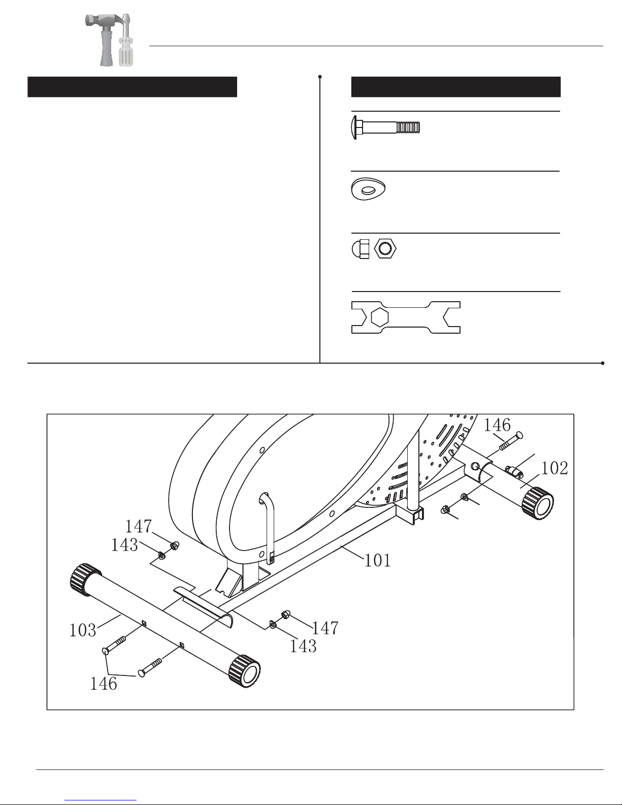
A s s e m b l y S t e p 1 Hardware & Tool Required
118A
147143
Bolt
#146 Carriage Bolt (M10x57 mm)
[4 Pieces]
Washer
#143 Arc Washer
( φ10x2.0xφ25xR28)
[4 Pieces]
Nut
#147 Nut (M10)
[4 Pieces]
Tools
#168 Tool 1 (2-S17,S19) [1 Piece]
S17
With the help of an assistant, attach the Rear Stabilizer
(#103) to the rear of the Main Frame (#101). Insert two
Carriage Bolts (#146) through the Rear Stabilizer
(#103) followed by the rear of the Main Frame (#101).
Secure them together using two Arc Washers (#143)
and two Nuts (#147). Now, attach the Front Stabilizer
(#102) to the front of the Main Frame (#101). Insert two
Carriage Bolts (#146) through the Front Stabilizer
(#102) followed by the front of the Main Frame (#101).
Secure them together using two Arc Washers (#143)
and two Nuts (#147).
Note:
Pls note that the Front Stabilizer (#102) has Front
Rollers (#118A) that spin for ease of relocating the unit.
Assembly Instructions
BR1830 Page 5
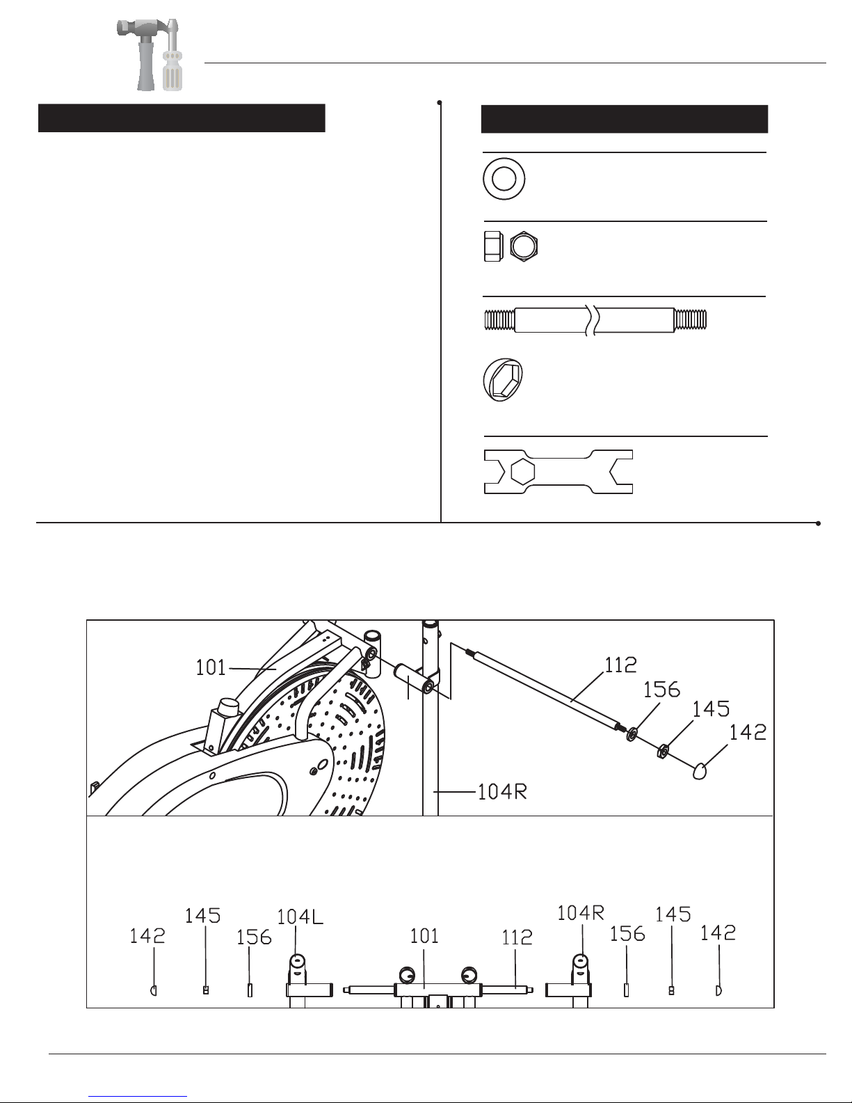
Assembly Step 2
Pivot Tube(See Note)
BR1830 Page 6
Note:
Make sure Left /Rgiht Coupler Bar (104L/104R) are at the correct side when its horizontal pivot tube, which is
welded at the top, faces the REAR of the machine as seen from the user.
Washer
#156 Washer
(φ10.2xφ25x2 mm)
[2 Pieces]
#145 Nylon Nut (M10)
[2 Pieces]
Others
#112 Handlebar
Axle (φ16x410 mm)
[1 Piece]
#142 Cap
(S16)
[2 Pieces]
Tools
#168 Tool 1 (2-S17,S19)
[2 Pieces]
Hardware & Tool Required
Remove the Nylon Nuts (#145) and Washers (#156) that
are pre-assembled on the Handlebar Axle (#112) and set
them aside as they will be used in a later process.
Insert the Handlebar Axle (#112) through the main frame.
Make sure the Handlebar Axle (#112) is centered. If you
encounter too much friction, try using WD40 or Vaseline as
a lubricant.
Attach Left Coupler Bar (#104L) and Right Coupler Bar
(#104R) to the main frame via the Handlebar Axle (#112).
Again, use WD40 or Vaseline to reduce friction if needed.
Once the Left Coupler Bar (#104L) and Right Coupler
Bar (#104R) are correctly situated, fasten the end of the
Handlebar Axle (#112) with a Washer (#156) and a Nylon
Nut (#145) on each side. Then cap each end with a Cap
(#142).
Note:
Make sure Left/Right Coupler Bar (#104L/#104R) are at
the correct side when its horizontal Pivot Tube faces the
REAR of the machine as seen from the user. Please refer
to the drawing in below.
55
40 1 2 3 4
55
40 1 2 3 4
STEP3:
Assembly Instructions
Assembly Instructions
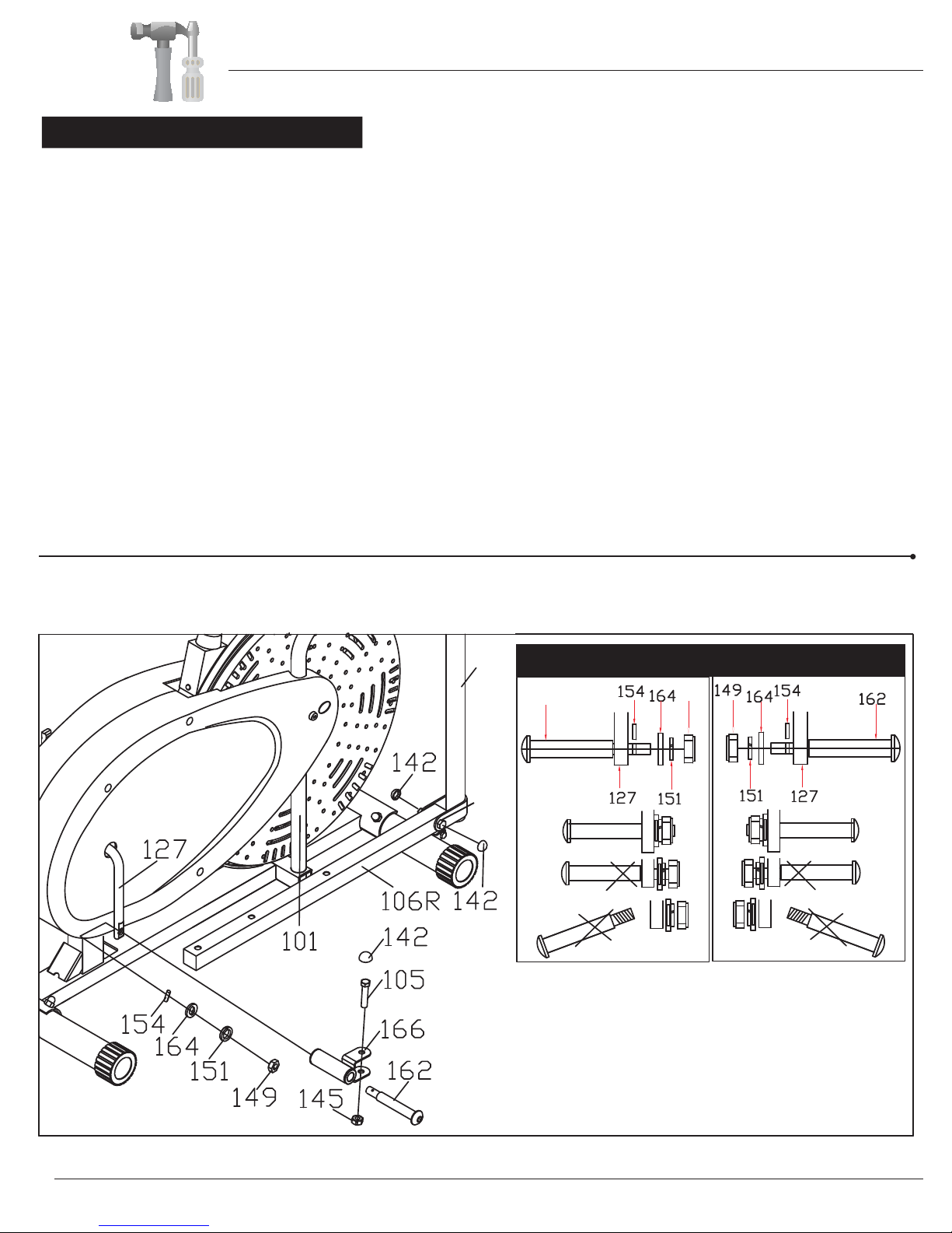
Assembly Step 3
Right Crankshaft
Note:
Keep the Right/Left Pedal Hinge Bolt (#162/163) perfectly
straight as they go through the Pedal Connection Joint
(#166) and the Crankshaft (#127). If the Right/ Left Pedal
Hinge Bolt (#162/163) are connected to the Crankshaft
(#127) incorrectly, or, the Special Washer (#164) does
not fit the Lock Pin for Pedal Hinge Bolt (#154) tightly,
damage to the Right/ Left Pedal Hinge Bolt (#162/163)
and Crankshaft (#127) will occur.
Attach the Pedal Connection Joint (#166) to the Right Pedal Tube (#106R). Insert a Hex Bolt (#105) through the upper
bracket of the Pedal Connection Joint (#166), followed by Right Pedal Tube (#106R) then the lower bracket of the Pedal
Connection Joint (#166). Secure them with a Nylon Nut (#145).
Attach three Caps (#142) on three Hex Bolts (#105) as illustrated in the drawing below.
Align and attach the Pedal Connection Joint (#166) on the Right Pedal Tube (#106R) to the right Crankshaft (#127). Insert
the Right Pedal Hinge Bolt (#162) through Pedal Connection Joint (#166) and Crankshaft (#127). Secure the Right Pedal
Hinge Bolt (#162) tightly into the Crankshaft (#127) by turning CLOCKWISE.
After that, insert a Lock Pin for Pedal Hinge Bolt (#154) to the small hole located at the end of the Pedal Hinge Bolt (#162).
Fit the Special Washer (#164) over the Lock Pin for Pedal Hinge Bolt (#154) and the Pedal Hinge Bolt (#162), then, secure
with a Spring Washer (#151) and a Right Nylon Nut (#149).
Repeat the above process on the left side of the machine.
Remove Hex Bolts (#105) and Nylon Nuts (#145) that are pre-assembled on the Pedal Connection Joint (#166) and set
them aside as they will be used in a later process.
163 148
104R
105
Left Crankshaf
BR1830 Page 7
Assembly Instructions
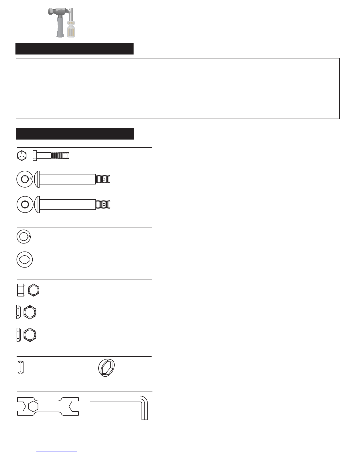
Assembly Step 3
#154 Lock Pin for Pedal Hinge
Bolt (φ3x16 mm)
[2 Pieces] #142 Cap
(S16)
[6 Pieces]
Tools
#168 Tool 1 (2-S17,S19)
[1 Piece]
#169 Tool 2 (S8)
[1 Piece]
Hardware & Tool Required
Bolt
#105 Hex Bolt (M10x55 mm)
[2 Pieces]
#162 Right Pedal Hinge Bolt
[1 Piece]
#163 Left Pedal Hinge Bolt
[1 Piece]
Washer
#151 Spring Washer
( D12)
[2 Pieces]
#164 Special Washer
(φ25xφ13x17x3.0)
[2 Pieces]
Nut
#145 Nylon Nut (M10)
[2 Pieces]
#148 Left Nylon Nut
(B0.5x20 S19)
[1 Piece]
#149 Right Nylon Nut
(B0.5x20 S19)
[1 Piece]
Others
IMPORTANT:
Secure both pedal hinge bolts every 30 days. Through regular use, the pedal hinge bolts may still come loose even when the
initial assembly was secure. DO NOT operate the Body Rider when these parts are loose!
WARNING:
Failure to keep these parts securely fastened will severely damage your Body Rider and may cause injury to the user. This
damage is not a sign of defect and is NOT covered by your limited warranty. The manufacturer is NOT liable for any damage
or injury resulted in this manner.
BR1830 Page 8
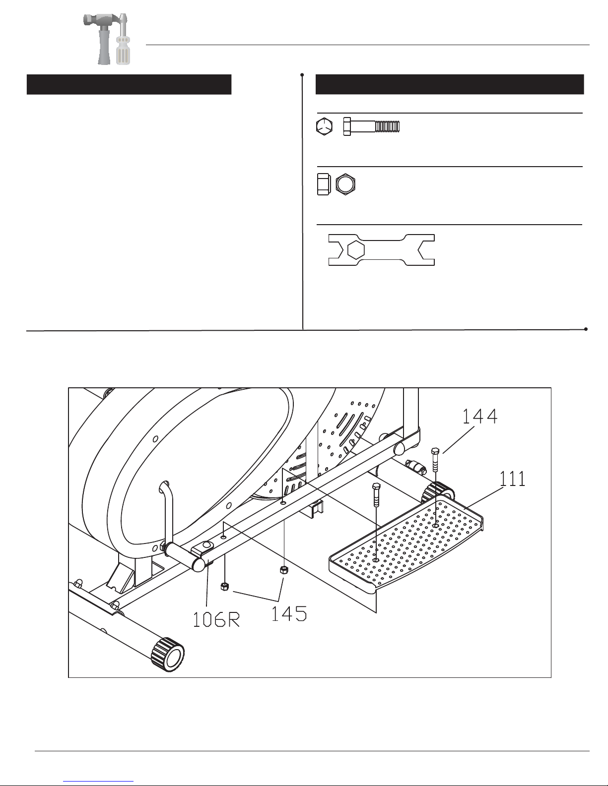
Assembly Step 4
Hardware & Tool Required
Tools
#168 Tool 1 (2-S17,S19)
[1 Piece]
S17
Bolt
#144 Hex Bolt (M10x45 mm)
[4 Pieces]
Nut
#145 Nylon Nut (M10)
[4 Pieces]
Attach the Right Pedal (#111) to the Right Pedal Tube
(#106R) and secure them together using two Hex Bolts
(#144) and two Nylon Nuts (#145).
Repeat this process on the other side.
Assembly Instructions
BR1830 Page 9

Assembly Step 5 Hardware & Tool Required
Bolt
#157 Screw (M5x16 mm)
[2 Pieces]
Others
#117 Knob Bolt
(M8x36 mm)
[2 Pieces]
Tools
#170 Tool 3 (S13-14-15)
[1 Piece]
A. Handlebar Assembly:
1). Dual-action mode: To allow Left/Right Handlebar
(#107L/107R) to move along with the movement of
the Pedals (#111), attach the Left/Right Handlebar
(#107L/107R) to the Left/Right Coupler Bar (#104L
/104R). Select a height setting that is comfortable
to the user, and make sure both handlebars are set
at the same height. Lock Left/Right Handlebar
(#107L/107R) in place with two Knob Bolts (#117).
2). Fixed mode: To keep the Left/Right Handlebars
(#107L/107R) stationary, attach them to the two
tubes on the Main Frame (#101) between the Left
/Right Coupler Bars (#104L/104R). Set the Left
/Right Handlebars (#107L/107R) at the same
height, and, secure them with two Knob Bolts (#117).
B. Electronic Monitor Assembly:
Remove the Screws (#157) that are pre-assembled on
the Main Frame (#101) and set them aside as they will
be used in a later process.
Attach the Electronic Monitor Base (#167) to the Main
Frame (#101), secure them with two Screws (#157).
Connect the Sensor Wire (#126) to the Wire on the back
of the Electronic Monitor (#150). Attach the Electronic
Monitor (#150) to the Electronic Monitor Base (#167).
AB
#42 WASHER FOR M10 BOLT,T2.0 1PC
#42 WASHER FOR M10 BOLT,T2.0 1PC
#42 WASHER FOR M10 BOLT,T2.0 1PC
Assembly Instructions
BR1830 Page 10

Tension Adjustment
The assembly of your Body Rider is now complete. As you try it for the first time, you should adjust the tension to a desirable
level before you begin a full workout.
For slight tension adjustment, simply turn the Tension Adjustment Knob (#136) found at the top center. Tension level can be
manipulated this way to vary intensity of workout as you exercise.
For greater tension adjustment, you may loosen or tighten the Friction Belt (#135) by re-strapping it. To do so, first turn the
Tension Adjustment Knob (#136) all the way to the loosest setting. Then re-strap the belt at the buckle on the main frame,
just beneath the flat beam at the top center. The more length you allow for the Friction Belt (#135) to wrap around the wheel,
the less friction it will cause. Re-adjust the Tension Adjustment Knob (#136) after you finished re-strapping.
Remove the three Washers (#44) and three Nylon Nuts (#40) that are pre-assembled on the back of the Seat (#63) and
set them aside as they will be used in a later process. Attach the Seat (#63) onto the Horizontal Seat Bar (#61) and
make sure that the Seat (#63) is pointing directly toward the short end of it and then tighten with three Washers (#44)
and three Nylon Nuts (#40) that were previously removed. The Knob (#68) can be loosened to adjust the distance of
the seat from the handle bars. Make sure to tighten the knob after making any adjustment. Insert the Seat Post (#60)
into the mouth of the post that is protruding from the Main Frame (#01). Make sure the holes on the Seat Post (#63)
are facing the right before inserting. The Spring Loaded Knob (#67) has a safety feature that allows you to loosen it
by turning it counter clockwise three times as you pull it outward. Adjust the seat height and then pop the knob back
in. Tighten the knob by turning clockwise. See the illustration below.
Assembly Instructions
Reversible Movement
Forward pedaling emphasizes your quadriceps muscles (front thighs), while backward pedaling emphasizes your hamstrings
(back thighs). Take advantage of this fact to make your workout less fatiguing, and more fun.
BR1830 Page 11

Safety Instructions
• Make sure all bolts are tightened.
• Check for loose parts and components
• Check to see if there are any tears or bends in the welding or metal.
• Be sure that all adjustment locking devices and safety devices are
properly engaged prior to use!
BR1830 Page 12

Computer Operation
SPECIFICATIONS:
TIME………………………………………0:00-99:59
SPEED……………………………………0.0-99ML/H
DISTANCE ……………………………0.0-999.9ML
CALORIES………………………………0.0-9999CAL
KEY FUNCTION:
MODE: This key lets you to select and lock on to a particular function you want.
OPERATION PROCEDURES:
1.AUTOON/OFF:
◆The system turns on when any key is depressed of when it receives an input from the speed
sensor.
◆The system turns off automatically when the speed sensor has no signal input or no key are pressed for
approximately 4 minutes.
2. RESET:
The unit can be reset by changing battery or pressing the MODE key for 3 seconds.
3. FUNCTION:
Top portion of LCD Display
oSpeed: Display the current speed
Lower portion of the LCD Display (Press Mode to alternate through the following functions)
oTime: Display the total amount of time using the machine.
oDistance: Display the distance travelled.
oCalories: Display the amount of calories burned.
oScan: Automatically alternate between the different functions. (Time, Distance, Calories)
4.BATTERY:
This monitor requires one (or two) "AA" Battery(ies).
You can replace the batteryfrom the back of the unit.
BR1830 Page 13
Before use, you must read and understand all instructions & warning stated in this Owner's Manual as well as
posted on the equipment.
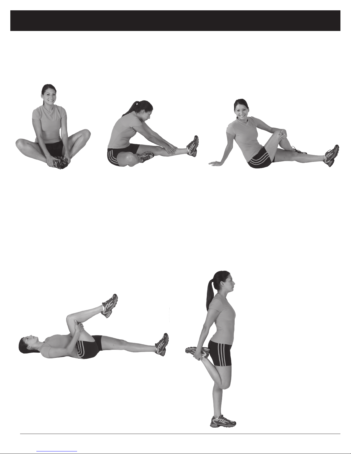
Warm-Up Instructions
Groin Stretch
1. Sit with your knees flexed
and soles of feet together.
2. Hold your ankles and bend
at your hips (keep your
back straight) as you press
your knees toward the
floor with your elbows.
Hamstring Stretch
1. Sit with your left leg extended and bend your right
leg at the knee as you place the sole of your right foot
against the inner thigh of your extended leg.
2. Flex the foot of your extended leg (toes pointed
toward ceiling) and gently bend forward from your
hips; keep your back straight.
3. Reach your hands on your extended leg as far as pos-
sible and then switch legs and repeat.
Trunk Twister
1. Sit with your leg extended and
bend your right knee as you cross
your right leg over your left leg.
Your right foot should be flat on the
floor alongside your left knee.
2. Place your left arm on the outside
of your right leg and pull against
that leg while twisting your trunk
as far as possible to the right. Place
your right hand on the floor behind
your buttocks. Reverse leg posi-
tions and repeat.
Hip Stretch
1. Lie on your back and raise your right leg as you clasp both hands
under the back of the knee. Keep your left leg straight.
2. Gently pull your right leg toward your trunk without raising your
upper body. Switch leg positions and repeat.
The following flexibility exercises are provided to you as a means to prevent injury while you are exercising. A
proper warm-up routine decreases the chance of injuring your muscles while you are exercising. Please take the
time to do these flexibility exercises before and after each time you exercise.
Quadriceps Stretch
1. Stand on your left leg and hold onto
a support with your left hand.
2. Flex your right leg behind you, grasp
your ankle or foot with your right
hand and pull your foot toward your
buttocks. Keep your back straight
and right knee pointed down. Repeat
on the other leg.
BR1830 Page 14
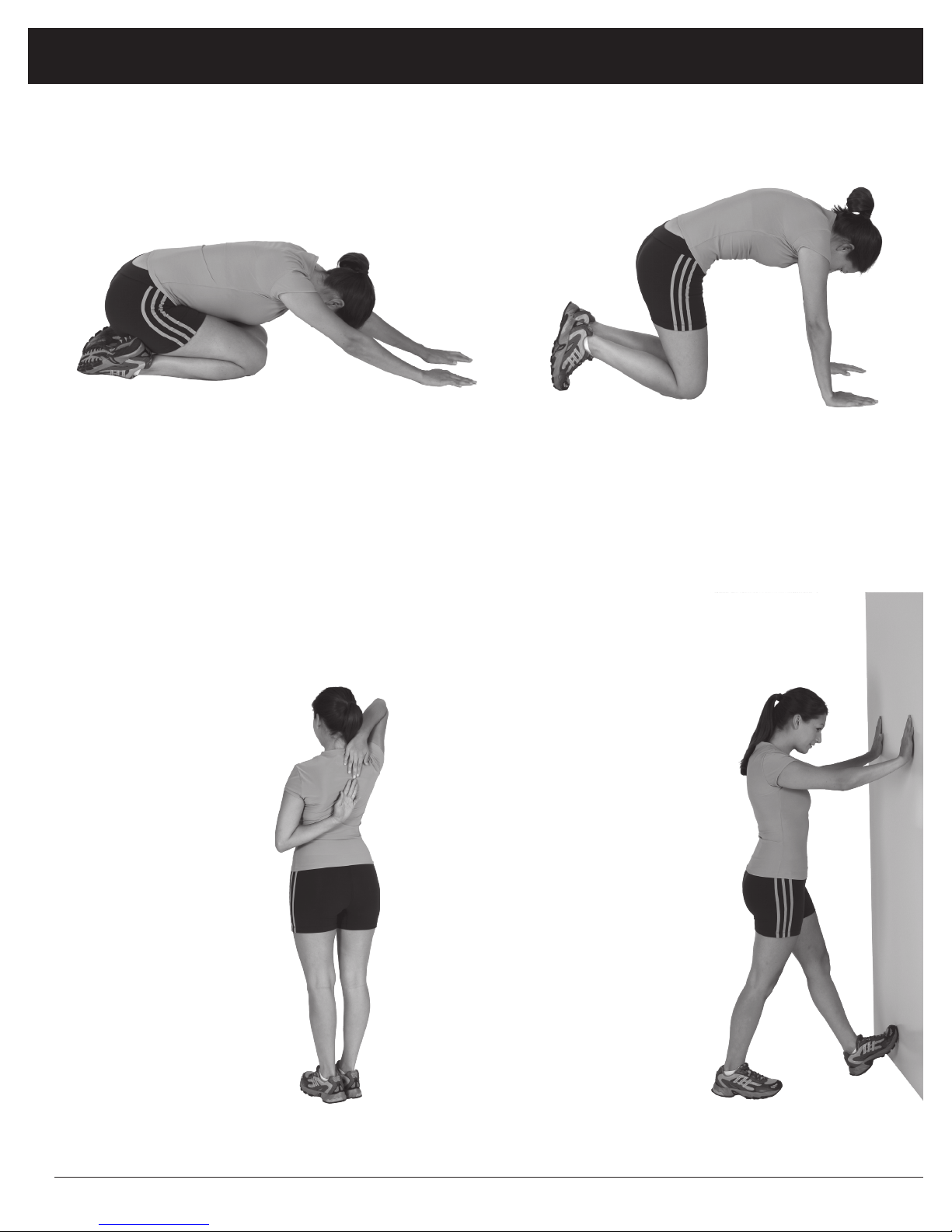
Trunk Flexion, Prone
1. Assume the depicted position on your hands and knees. Stretch your hands out in front of you and then slowly start to pull
them back in toward your body as you tuck your chin and arch your back upward.
2. Return to the starting position slowly.
Shoulder Stretch
1. Bring your right hand over
your right shoulder to the
upper back and bring your
left hand under your left
shoulder to the upper back.
2. Try to reach your finger-
tips. If you are not able to
reach your fingertips, use
a towel as an extension of
your hands and gently pull
one hand toward the other.
Reverse arm positions and
repeat.
Calf Stretch
1. Place both hands against
a wall to aid your balance.
Press the ball of your left foot
against the wall and keep the
heel of the same foot rested
on the floor (make sure your
left knee is bent).
2. Slowly start to straighten your
left knee and you will feel
the muscles in your left calf
stretch. Switch leg positions
and repeat.
Warm-Up Instructions
BR1830 Page 15

Proof of purchase
version: 11-12-2010
BR 1830
Model Number BR 1830

This page intentionally left blank

This page intentionally left blank

Body Flex Sports, Inc. • 21717 Ferrero Parkway, Walnut, CA 91789 • Telephone: (888) 266 - 6789 • Email: info@bodyexsports.com
Table of contents
Other Body Flex Sports Elliptical Trainer manuals


