Body Flex Sports Body Champ BR1895 User manual

BR1895/2895
OWNER’S MANUAL
*This item is for consumer use only and it is not meant for commercial use.
OWNER’S MANUAL
*This item is for consumer use only and it is not meant for commercial use.

WARNING: SERIOUS INJURIES AND EVEN DEATH CAN OCCUR IF THE PROPER SAFETY PRECAUTIONS ARE NOT FOLLOWED.
The diagram below highlights and reviews many of the important Safety and Warning labels also found
on the unit. Please ensure any user of the unit familiarizes themselves with these Safety and Warning
guidelines before use.
PLEASE KEEP THESE INSTRUCTIONS FOR FUTURE USE & REFERENCE.
DO NOT DISCARD.
The use of this exercise equipment involves a RISK OF PHYSICAL INJURY as well as
property damage, which can be minimized by observing the following guidelines:
1. ALWAYS wear comfortable clothing
and shoes with good traction.
2. ALWAYS make sure all nuts and bolts
are secured before use. TIGHTEN
PEDAL HINGE BOLTS EVERY 30
DAYS.
3. STOP EXERCISING if you become
dizzy, nauseous, have irregular
heartbeats or breathing difficulties.
Contact your physician immediately.
4. ALWAYS keep a large mat under the
Equipment to protect the floor or carpet.
5. ALWAYS use your Equipment in a
warm, dry, level well-lit and ventilated
indoor area.
7. ALWAYS keep your Equipment clean
and free of dust, moisture, debris and
loose objects.
8. NEVER use the Equipment if you are
injured or have a physical condition
that impairs your balance. DO NOT
exercise under the influence of
medication or alcohol.
9. NEVER allow small children or pets to
approach the Equipment. It is not a
toy.
10. NEVER use the Equipment if you
exceed its weight limit of 250 lbs.
11. NEVER use the Equipment if it does
not function properly.
6. ALWAYS keep body and clothing free
and clear of all moving parts.
W A R N I N G !
!
BR1895/2895 Page 1
General Information
Warranty
Body Flex Sports warrants your product for
a period of 1 year for the frame and 90 days
on all parts if the item is used for the intended
purpose, properly maintained and not used
commercially. Any alterations or incorrect
assembly of the product will void this warranty.
Proof of purchase must be presented for any
warranty validation (no exceptions). This
warranty applies to the original purchaser only
and is not transferable.
This warranty does not cover abuse or defects
caused during use, storage or assembly.
During the warranty period, Body Flex Sports
reserves the right to:
a). provide replacement parts to the
purchaser in an effort to repair the item.
b). repair the product returned to our
warehouse (at the purchaser’s cost).
c). replace the product if neither of the two
previously mentioned actions effect repair.
This warranty does not cover normal wear and
tear on upholstery.
Questions
If you have any questions concerning the
assembly of your item or if any parts are
missing, please DO NOT RETURN THE
ITEM TO THE STORE OR CONTACT THE
RETAILER. Our dedicated customer service
staff can help you with any questions you may
have regarding the assembly of this unit and
can also mail you replacement parts.
Customer Support
Customer Support is open 9:00 a.m. to 5:00
p.m. (Pacific Time) Monday through Friday.
Please contact us by any of the following
means.
Body Flex Sports, Inc.
21717 Ferrero Parkway, Walnut, CA 91789
Telephone: (888) 266 - 6789
Fax: (909) 598 - 6707
Email: info@bodyflexsports.com
Safety
Before you undertake any exercise program,
please be sure to consult with your doctor.
Frequent strenuous exercise should be
approved by your doctor and proper use
of your product is essential. Excessive or incorrect
training may result to health injuries. Please read
this manual carefully before commencing the
assembly of your product or starting to exercise.
• Please keep all children away from this item
when in use. Do not allow children to climb or
play on them when they are not in use.
• Supervise teenagers while they use this unit.
• For your own safety, always ensure that there
is at least 3 feet of free space in all directions
around your product while you are exercising.
• Regularly check to see that all nuts, bolts and
fittings are securely tightened. Periodically
check all moving parts for obvious signs of
wear or damage.
• Clean only with a damp cloth, do not use
solvent cleaners. If you are in any doubt, do
not use your product; contact CUSTOMER
SUPPORT.
• Before use, always ensure that your product
is positioned on a solid, flat surface. If
necessary, use a rubber mat underneath to
reduce the possibility of slipping.
• Always wear appropriate clothing and
footwear such as training shoes when
exercising. Do not wear loose clothing that
could become caught in moving parts during
exercise.
• Do not use this unit if it is not functioning
properly or if it is not fully assembled.
• Do not use this unit for commercial purposes.
This unit is for home use only.
Storage and Use
Your product is intended for use in clean
dry conditions. You should avoid storage in
excessively cold or damp places as this may
lead to corrosion and other related problems.
Weight Limit
Your product is suitable for users weighing:
250 pounds or less.
• Before use, you must read and understand all
instructions & warnings stated in this Owner’s
Manual as well as posted on the equipment.
• It is the facility owner’s responsibility to properly
instruct users on the proper operation of the
equipment and to warn them of the potential
hazards.
• If at any time during exercise you feel faint, dizzy
or experience pain, stop and consult your
physician.
Assembling Tools
- Ruler with both metric and English measurements
- 2 x Adjustable Wrenches
- 1 x Philips (”Crosshead”) Screw Driver
•
Any adjustment devices that could interfere with
the user's movement on this unit should not be
left projecting.
Page 2
BR1895/2895
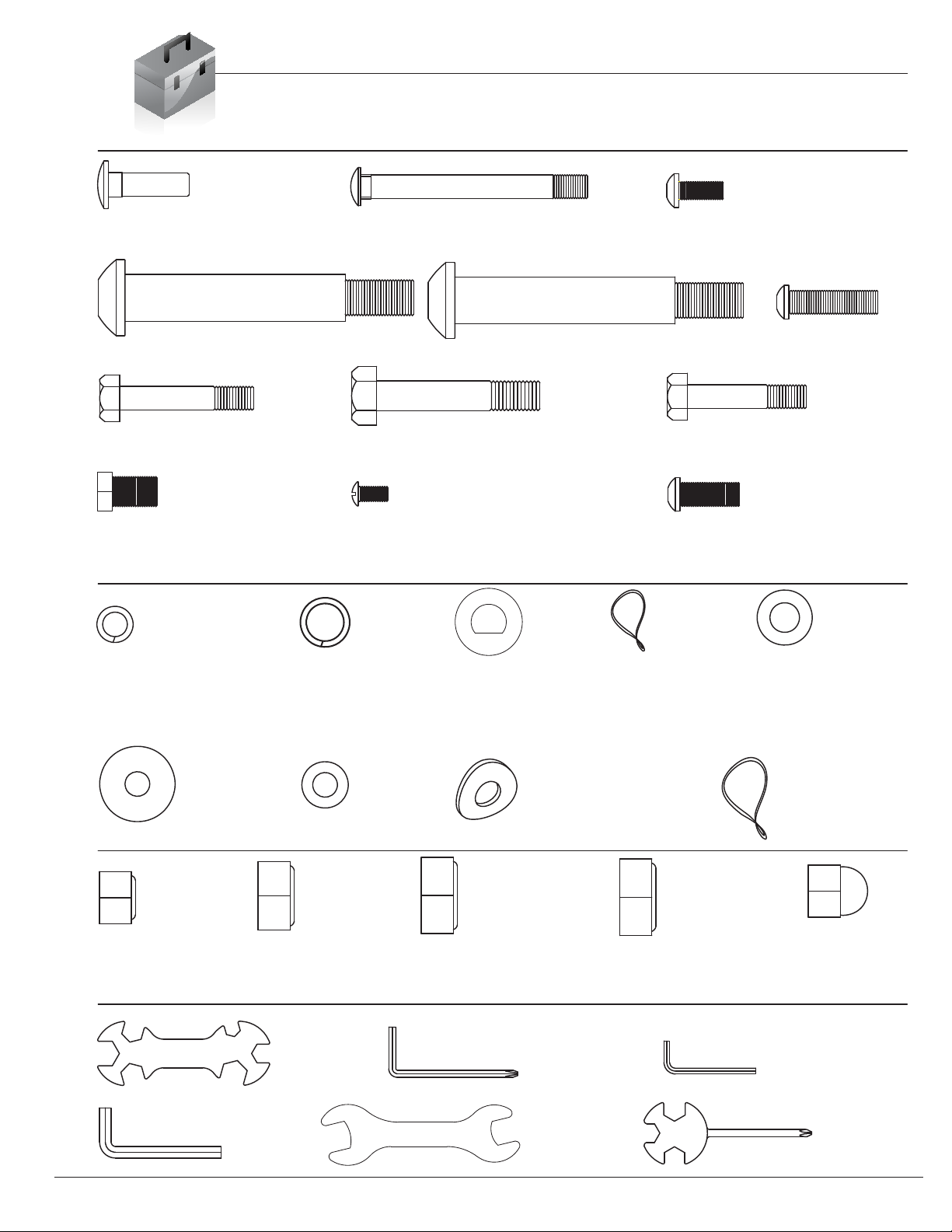
Hardware List
The following hardware is used to assemble your unit. Please take a moment to familiarize yourself with these items.
Please note, most of these parts are already pre-assembled on your unit. Do not be alarmed if you see parts on this
page that are not included in your hardware packet.
NUTS
WASHERS
BOLTS
#14. Carriage Bolt (M6x16 mm)
[4 Pieces]
#15. Carriage Bolt (M8x70 mm)
[4 Pieces]
#17. Bolt (M6x15 mm)
[4 Pieces]
#19. Bolt (M8x30 mm)
[2 Pieces]
#20. Hex Bolt (M8x45 mm)
[2 Pieces]
#21. Hex Bolt (M10x55 mm)
[2 Pieces]
#22. Hex Bolt (M8x40 mm)
[6 Pieces]
#23. Hex Bolt (M8x15 mm)
[2 Pieces] Pre-assembled
#25. Screw (M5x10 mm)
[4 Pieces] Pre-assembled
#16. Bolt (M8x20 mm)
[4 Pieces] Pre-assembled
#29. Spring Washer (M8)
[6 Pieces]
#30. Spring Washer
(1/2")
[2 Pieces]
#31. Washer (M8)
[2 Pieces]
Pre-assembled
#32 Wavy Washer
(1/2")
[2 Pieces]
#33. Washer (M10)
[2 Pieces]
#34. Washer
(M8, φ26 mm)
[2 PIeces]
#35. Washer
(M8, φ16 mm)
[8 Pieces]
#38. Nylon Nut (M8)
[8 Pieces]
#39. Nylon Nut (M10)
[2 Pieces]
#40. Left Nylon Nut
with BLACK inner nylon ring
[1 Piece]
#41. Right Nylon Nut
with WHITE inner nylon ring
[1 Piece]
Tools
Page 3
#66. Tool 1
[1 Piece]
#67. Tool 2
[1 Piece]
#68. Tool 3
[1 Piece]
#69. Tool 4
[1 Piece]
#70. Tool 5
[1 Piece]
#71. Tool 6
[1 Piece]
S10-13-14-15-17-19 S5 S8
S4 S17-19
S13-14-15
#18L. Left Pedal Hinge Bolt (1/2"x97 mm)
[1 Piece]
#18R. Right Pedal Hinge Bolt (1/2"x97 mm)
Pre-assembled [4 Pieces]
#36. Arc Washer (M8)
[8 Pieces]
Pre-assembled [4 Pieces]
#37. Wavy Washer (φ19 mm)
[2 Pieces]
Pre-assembled
#42. Nut (M8)
[4 Pieces]
[1 Piece]
Pre-assembled
BR1895/2895

BRM 3670 Stride Cycle Page ?
Parts Listing
The following parts list describes all of the parts illustrated on the
exploded diagram on the following page. Please note, most of
these parts are already pre-assembled on your unit.
Page 4
#Description #Description
01 Main Frame 34 Washer (M8, φ26 mm)
02 Center Post 35 Washer (M8, φ16 mm)
03L Left Pedal Tube 36 Arc Washer (M8)
03R Right Pedal Tube 37 Wavy Washer (φ19 mm)
04L Left Coupler Bar 38 Nylon Nut (M8)
04R Right Coupler Bar 39 Nylon Nut (M10)
05 Pulse Handle Bar 40 Left Nylon Nut with BLACK inner nylon ring
06L Left Pedal Connection Joint 41 Right Nylon Nut with WHITE inner nylon ring
06R Right Pedal Connection Joint 42 Nut (M8)
07L Left Handle Bar 43 Spacer
07R Right Handle Bar 44 Left Pedal
08 Front Stabilizer 45 Right Pedal
09 Rear Stabilizer 46 Monitor
10 Crank 47 Shroud Cover
11 Main Sensor Wire (Middle) 48 Bushing
12 Main Sensor Wire (Lower) 49 Left Shroud
13 Handle Pulse Wire 50 Right Shroud
14 Carriage Bolt (M6x16 mm) 51 Shroud Wheel
15 Carriage Bolt (M8x70 mm) 52 Screw (ST4.2x20 mm)
16 Bolt (M8x20 mm) 53 Round Cap (φ31.8 mm)
17 Bolt (M6x15 mm) 54 Hand Pulse Sensor
18L Left Pedal Hinge Bolt (1/2"x97 mm) 55 Washer (M4)
18R Right Pedal Hinge Bolt (1/2"x97 mm) 56 Round End Cap (φ25 mm)
19 Bolt (M8x30 mm) 57 Round End Cap (φ28.6 mm)
20 Hex Bolt (M8x45 mm) 58 Square End Cap (25x40 mm)
21 Hex Bolt (M10x55 mm) 59 Bushing
22 Hex Bolt (M8x40 mm) 60 End Cap for Rear Stabilizer
23 Hex Bolt (M8x15 mm) 61 End Cap for Front Stabilizer
24 Clamp Cover 62 Foam Grip for Pulse Handle Bar
25 Screw (M5x10 mm) 63 Foam Grip for Handle Bar
26 Adapter 64 Bushing
27 Bolt Cap (S14) 65 Wire Plug
28 Bolt Cap (S17) 66 Tool 1
29 Spring Washer (M8) 67 Tool 2
30 Spring Washer (1/2") 68 Tool 3
31 Washer (M8) 69 Tool 4
32 Wavy Washer (1/2") 70 Tool 5
33 Washer (M10) 71 Tool 6
BR1895/2895
This manual suits for next models
1
Table of contents
Other Body Flex Sports Elliptical Trainer manuals


Popular Elliptical Trainer manuals by other brands

NordicTrack
NordicTrack AudioStrider 990 PRO NTEL09811.2 user manual

Weslo
Weslo Momentum 4.0 Elliptical Manuale d'istruzioni

Progear Fitness
Progear Fitness Air elliptical pro 1307 owner's manual

Torque Fitness
Torque Fitness XPLLP owner's manual

Octane Fitness
Octane Fitness PRO3700C Operation manual

Xterra
Xterra FS5.8e owner's manual


