Body Life V-shade AnchorFree V12 User manual
..
1 / 40

2 / 40
Content
Chapter 1Introduction………….…..………………………….………………….………5
1.1 Parts…......................................................................................................6
1.2 Handpiece…………………………………………………………………………………..……7
1.2.1 168 Handpiece………………………………………………………………………………....7
1.2.2 108 Handpiece…………………………………………………………………........................8
1.3 Technical Speci ication……………………………………………………………………….…9
1.4 Parameters o Handpiece……………………………………………………………………..….9
1.5 Working Conditions………………………………………………………………………….…10
Chapter 2 Sa ety………………………………………………………………………………..…...11
2.1 Optic Sa ety…………………………………………………………………………….….……11
2.2 Sa ety Signs……………………………………………………………………………….…….11
Chapter 3 Operation……………………………………………………………………………..….12
3.1 Install Host Output……………………………………………………………....……..……….12
3.2 Disassemble Host Output……………………………………………………………..………...13
3.3 Stand 1………………………………………………………………………………………….13
3.4 Install Handpiece and Change Handpiece……………………………………………….……..14
3.5 Install Earth Line……………………………………………………………………………….17
3.6 Fill Water…………………………………………………………………………...…….…….17
3.7 Drain Water……………………………………………………………………………….…….19
3.8 Place the Equipment…………………………………………………………………….……...19
3.9 Start the Equipment…………………………………………………………………………….21
3.10 Main Inter ace…………………………………………………………………………………22
3.11 Error Noting……………………………………………………………………...……………24
3.12 Wireless IC Card………………………………………………………………………………26
3.13 Make Use o Wireless IC Card………………………………………………………………..28
3.14 Password………………………………………………………………………………………29
3.15 Treatment Procedure…………………………………………………………………………..30
3.16 Cryolipolysis Cloth……………………………………………………………………………31
3.17 Turn o the Equipment………………………………………………………………………..32
Chapter 4 Maintenance and Troubleshooting………………………………………………………32

3 / 40
4.1 Add Water and Change Water in Time………………………………………………………….32
4.2 Change Filter o Equipment…………………………………………………………………….32
4.3 Change Filter o Handpiece……………………………………………………………..….…..34
4.4 Move the Equipment…………………………………………………………………….….…..34
4.5 Troubleshooting………………………………………………………………………….….….35
Chapter 5 Clinical Guide……………………………………………………………………….…..38
5.1 Working Mechanism……………………………………………………………………….…...38
5.2 Applications………………………………………………………………………………….…38
5.3 Customer Contraindications……………………………………………………………………38
5.4 Treatment Course……………………………………………………………………………….38
5.5 Customer's Feeling during Treatment…………………………………………………………..38
5.6 Treatment Skills………………………………………………………………………………...39
5.7 Treatment Part…………………………………………………………………………………..39
5.8 Notes a ter Treatment…………………………………………………………………………...39
5.9 Suggestions or Beauty Salon…………………………………………………………………..39
5.10 Questions and Answers………………………………………………………………………..39

4 / 40
Beijing Anchor ree Technology Co., Ltd. was established in 2003, which is a
government-supported high-tech company. In 2008, we took part in China Chamber o
International Commerce (CCOIC) and serve as an honorary member. Since its inception, the
company has been adhering to the "integrity, pragmatic; innovative, progressive" business
philosophy, insisting on "Pro essional, Exceptional" slogan, ocusing on R & D, manu acturing,
sales and service o non-invasive medical and cosmetic equipments. Meanwhile, we constantly
improve the product quality, technical standards and service quality, always making the best e orts
to provide better products and technical support or global buyers.
By nearly 10 years o hard work in the domestic market, the company won a good reputation and
rapid development. At present, our products cover 7 series like CO2 ractional laser, mid-in rared
1550nm ractional laser, 808NM hair removal diode laser, IPL (intense pulsed light), RF (RF),
E-light, water oxygen jet system, vacuum / cavitation / cryolipolysis system.etc. These totally about
50 models are exported to ive continents in over 80 countries.
In 2007 we completed ISO9001 and ISO13485 international quality system certi ication as the irst
in China. With the e orts the vast majority o our products have been given medical CE
certi ication; we have established a strong R & D center with nearly 30 people in R&D team. A
number o our research results have illed the domestic blank and got patents, among which 4
Results got invention patents, 8 results got utility model patents.
Beijing Anchor ree actively promotes the international development strategy, and has established a
close working relationship with many international well-known agents. We have set up overseas
branches like Anchor ree (Japan) Co., Ltd., Anchor ree (Hong Kong) International Co., Ltd.,
BTF.etc. In uture we will still increase international market e orts to expand and promote the
progressive realization o branding, marketing, team, technology, management to meet the
international standards.
Looking ahead, we will seize the opportunity to increase the product innovation ability, speed up
the process o internationalization and achieve scale development o economical leaps. Anchor ree
bounds to become internationally competitive, internationally renowned leading enterprise o
medical and beauty equipments, to establish "Anchor ree” as an international brand, to achieve the
dream o “repay to the community and serve or the customer” o Anchor ree people!
Telephone◇0086-010-81504046 /4737 /4750/4683
Fax◇ 010-81502271
Web:

5 / 40
Chapter 1 Introduction
This chapter is a general illustration.
Handpiece s
tand
3
Host output
Handpiece stand 2
Screw
Power switch
Fuse
Fill water/Drain water
Air exhaust
Earth line connector
Power supply
Electricity breaker
Standby handpiece connector
Emergency switch
Water level
Working handpiece connector
Stand 1

6 / 40
1.1 Parts
Host×1 168 handpiece×2 108 handpiece×2
Host output ×1 Stand×1 Funnel×1
Earth line×1 Power line×1 Air exhaust with a hole ×1
Filter User manual Warranty card
7 / 40
1.2 Handpiece
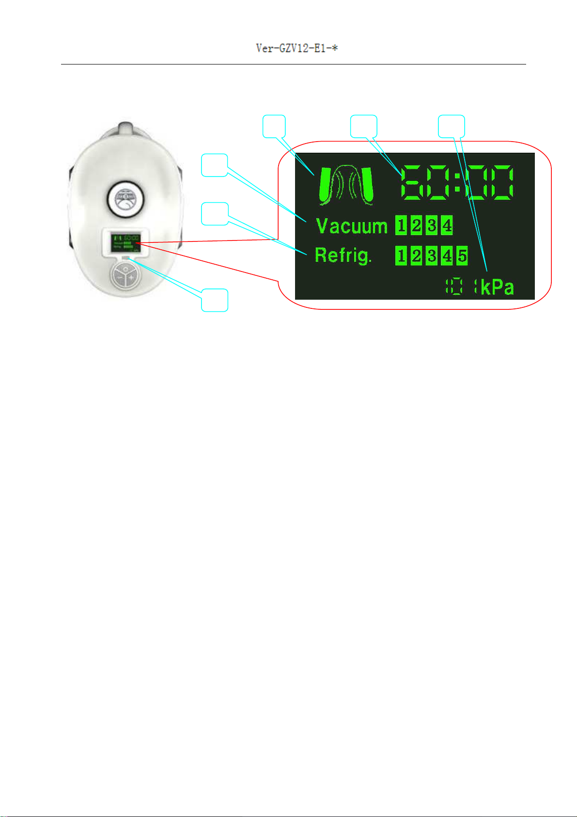
1.2.1 1 8 Handpiece
ARe rigeration7 levels;
BVacuum8 levels;
CVacuum situationGreen-----it is ON; Black-----it is OFF;
DWork timeCountdown;
EAbsolute value;
FPilot lamp
I 168 handpiece connects with le t output connector, le t side o host screen is blue and
pilot lamp o handpiece is blue;
I 168 handpiece connects with right output connector, right side o host screen is yellow
and pilot lamp o handpiece shows yellow;
a) Press “-”, “+” key to adjust vacuum
b) A ter adjusting vacuum, press “ ” key to start vacuum
c) You could also adjust vacuum on host screen
d) You have to start re rigeration on host screen
e) Press “ ” key to close re rigeration
) A ter you close re rigeration and handpiece’s temperature goes to 8pilot lamp on
handpiece will lickerpress “ ” key to close vacuumcould also close vacuum on
host screen
D
C
B
A
E
F

8 / 40
1.2.2 108 Handpiece
Vacuum lampVacuum is ON------vacuum lamp is red;
Vacuum is OFF------vacuum lamp is o
Re rigeration lampRe rigeration is ON------re rigeration lamp is red;
Re rigeration is OFF------ re rigeration lamp is o
Output connector lamp
I 168 handpiece connects with le t output connector, le t side o host screen is blue and
pilot lamp o handpiece is blue;
I 168 handpiece connects with right output connector, right side o host screen is yellow and
pilot lamp o handpiece shows yellow;
a) Press “-”, “+” key to adjust vacuum
b) A ter adjusting vacuum, press “” key to start vacuum
c) You could also adjust vacuum on host screen
d) You have to start re rigeration on host screen
e) Press “” key to close re rigeration
) A ter you close re rigeration and handpiece’s temperature goes to 8pilot lamp on
handpiece will lickerpress “” key to close vacuumcould also close vacuum on
host screen
Vacuum lamp
Output connector lamp
Re rigeration lamp

9 / 40
1.3 Technical Specifications
1.4 Parameters of Handpiece
Form 1
Parameters scope
Handpiece Refrigeration
*Level
Vacuum
*Level
Work time
*min
168 handpiece 1~7 1~8 10 ~90
108 handpiece 1~7 1~8 10 ~90
Form 2
Default parameter
Handpiece Refrigeration
*Level
Vacuum
*Level
Work time
*min
168 handpiece 3 3 60
108 handpiece 2 3 60
Items Specifications
Screen 1 Host screen: 10.4″TFT Chromatic Touch Screen
2 168 handpiece screen: 1.4″ LCD screen
Working mode Continuous
Adjust scope 10min90min
Negative pressure scope 1. Absolute value: 100kPa -20kPa
2.Relative value: 0kPa -80kPa
Vacuum levels 18, adjustable, the higher, the stronger
Re rigeration levels 17, adjustable, the higher, the stronger
Sa ety checking Real time on line
Number o handpiece 4 handpiece (168 handpiece---2 ones; 108 handpiece---2 ones)
Treatment area o tips 168mmx60mm108mmx45mm
Rated input power 750VA
Power supply AC230V±10%50Hz±1Hz/ AC110V±10%60Hz±1Hz
Net weight 55kg
Physical dimension 570mm×490mm×1050mm
Host output’s adjust scope 0-45
0
( orward)
Wireless IC card management system

10 / 40
Form 3 Treatment item
1.5 Working Conditions
1 Environmental temperature o operation10ºC—30ºC;
2 Environmental temperature or keeping the equipment-20 ºC —50ºC;
3 Relative humidity≤70%;
4 Air pressure860hPa1060hPa;
5) Environment requestAvoid direct radiation o intense light
Note:
1) If the temperature in the room is too low or the equipment has not been used for any days,
you shall make the temperature of the whole system recover to 10 ºC or higher before
starting it.
2) You shall not use this equipment in humid environment
Handpiece Treatment item
168 handpiece Stomachbuttockwaist, leg
108 handpiece Backstomachthigh, buttock , waist, chin, upper arm

11 / 40
Chapter 2 Safety
This chapter shows sa ety measures needs to be considered when you use this equipment. The
operators and maintenance person shall be amiliar with the sa ety requirements and procedures
when they use the equipment.
2.1 Optic Safety
1) Be sure that rated input voltage written on the label is coincident with the supply in the
location;
2) The maintain process can only be carried out ten minutes a ter the power has
been shut o and the electric line has been unplugged. Otherwise, there is
danger to the personnel or the equipment;
3) There is dangerous high-voltage in the equipment. So no one is allowed to
disassemble an y parts o the machine except the technical personnel appointed
by our company;
4) Good earthing is very important to operation sa ety. This equipment has good earthing by
yellow and green wires in power line. (Picture A);
5) Power switch (Picture B) or turn on or turn o the equipment;
6) Emergency switch (Picture C): Press it while emergency to cut o electricity;
7) Electricity breaker (Picture D): When electricity is abnormal, it will be OFF to cut o
electricity
Picture A Picture B Picture C Picture D
2.2 Safety Signs
1″ means earth line;
2″ “AC230V 50Hz” or “ AC110V 60Hz” is power supply;
3″ “FUSE 10A” or “FUSE 15A” is value o use
12 / 40
Chapter 3 Operation
3.1 Install Host Output
Picture 1 Picture 2
Picture 3 Picture 4
A
C

13 / 40
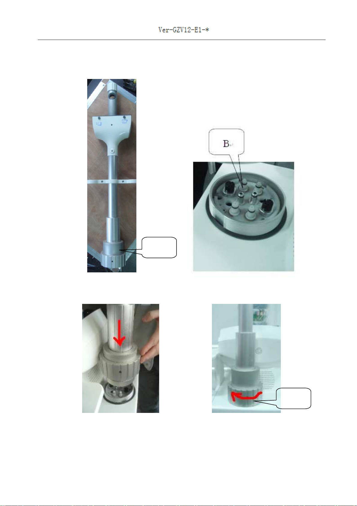
A (Picture 1) is the host output;
B (Picture 2) is in the equipment;
Insert A into B (Picture 3);
Screw C (Picture 4)
3.2 Disassemble Host Output
First disassemble handpiece (re er to 3.4);
Put handpiece in a sa e place;
Disassemble stand 1 (re er to 3.3);
Loosen C (Picture 4);
Pull out A (Picture 1);
Normally we don’t disassemble the host output and we disassemble it while checking equipment or
transportation
3.3 Stand 1
Picture 5
Installation: (Picture 5)
Insert stand 1 into host output;
Normally, the length is 50cm;
Fix the screw
Adjustment: (Picture 5)
Normally we don’t adjust stand 1;
I adjustment is needed, irst take out the handpiece pipe rom D and loosen screw;
Adjust stand 1;
D
14 / 40
Fix screw;
Put handpiece pipe back into D
Disassemble: (Picture 5)
First disassemble handpiece (re er to 3.4);
Put handpiece in a sa e place;
Loosen screw;
Take out stand 1
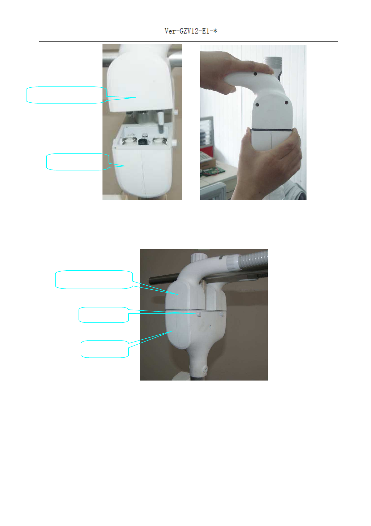
3.4 Install Handpiece and Change Handpiece
Handpiece connector
168 handpiece
Handpiece connector
108 handpiece
15 / 40
Picture 6
Picture 7
Hndpiece connector
Host output
Unlock key
Handpiece connector
Host output

16 / 40
Picture 8
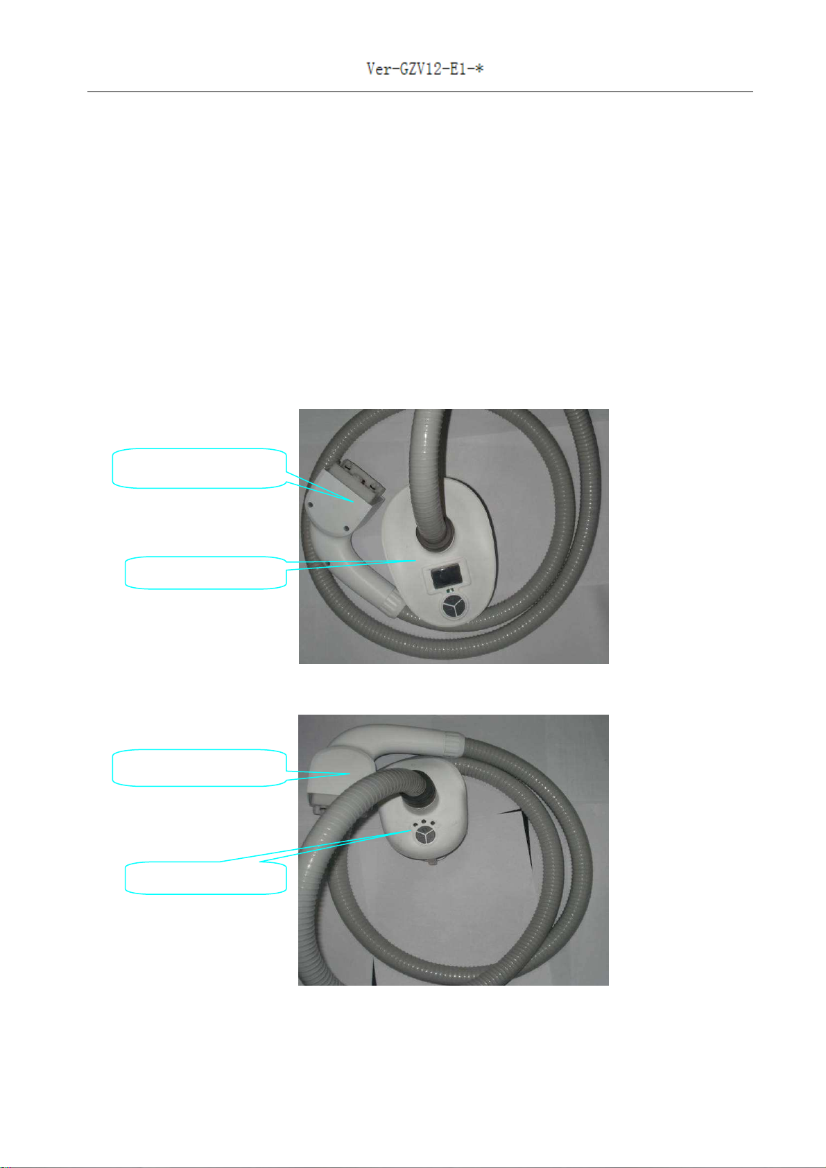
In Picture 8:
A is connector o standby handpiece (not working now);
B is handpiece stand 2, which is or working handpiece;
C is handpiece stand 3, which is or standby handpiece (not working now)
Handpiece installation:
Insert working handpiece’s connector into host output until you hear the sound (Picture 6);
Put working handpiece’s pipe into D (Picture 5);
Put working handpiece on stand 2(B in Picture 8);
Place the standby handpiece on stand 3(C in Picture 8);
Place the standby handpiece’s connector like A in picture 8
Change handpiece:
Press the key (Picture 7), at the same time, pull out the handpiece connector;
Take out handpiece pipe rom D (Picture 5);
Place the handpiece you just taken down in C (Picture 8) and put its connector on B in picture 8;
Insert working handpiece’s connector into host output until you hear the sound (Picture 6);
Put working handpiece’s pipe into D (Picture 5);
Put working handpiece on handpiece stand 2 (B in Picture 8);
B
C
A

17 / 40
3.5 Install Earth Line
Normally, you need not install the earth line;
In the ollowing situation, you have to install the earth line:
1. When you eel like needle hurt your skin during treatment;
2. There is no earth line in the power outlet;
Installation:
Be ore turning on the equipment, connect one side o the earth line with A ( ollowing picture)
and connect the other side o the earth line to metal touching the earth (like water pipe, heater
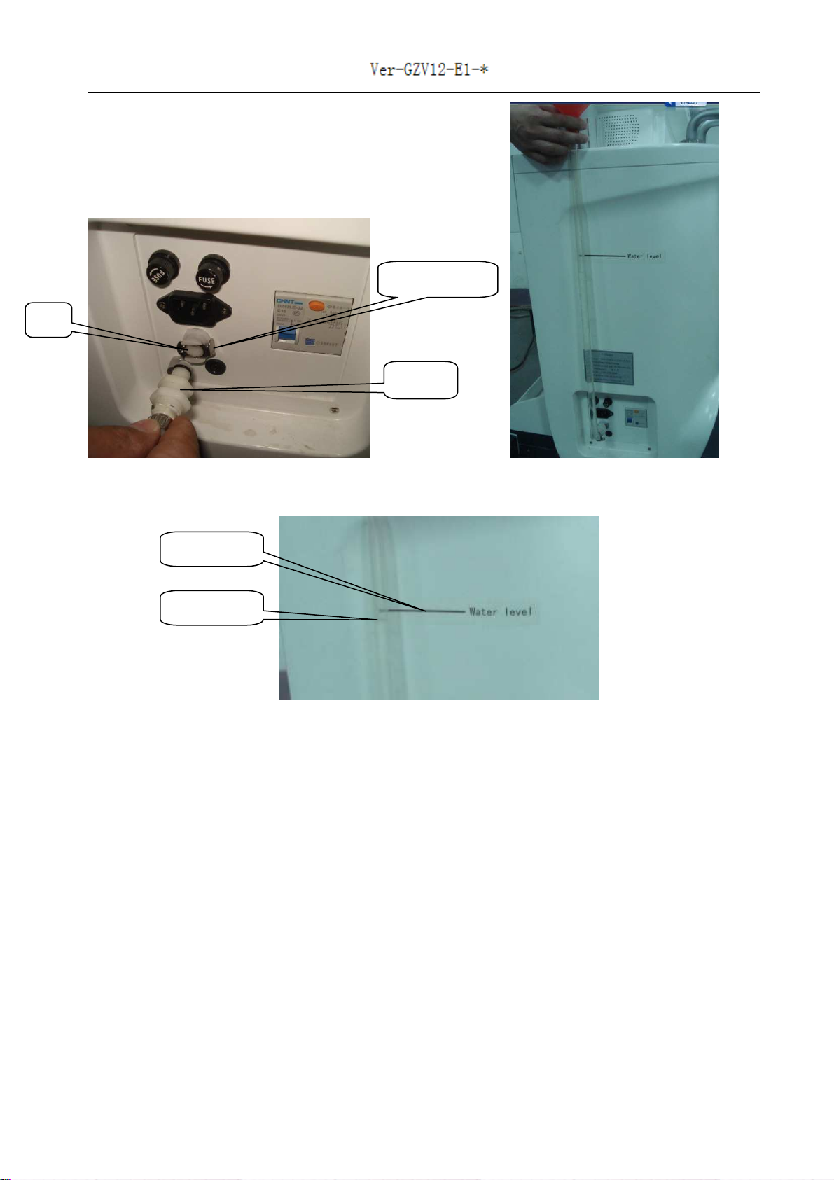
3. Fill Water
Use puri ied water or water without h ydronium. Strictly prohibit mineral water.
If you first use this equipment, please take the following steps to fill water:
Picture 9
A
18 / 40
Picture 10
Picture 11
1) Use the cap with a hole or the air exhaust (Picture 9)
2) Prepare 2.5-3L water;
3) Insert unnel into A (Picture 10) until you hear the sound;
4) Fill water;
5) When water in the pipe gets the “Water level” sign (Picture 11), stop illing water;
6) Press unlock key (Picture 10) until you hear sound, you pull out the unnel;
7) Install the handpiece, start the equipment and wait or 2-3 minutes;
8) Turn o the equipment;
9) Insert unnel into A (Picture 10) until you hear the sound;
10) Fill water;
11) When water in the pipe gets the “Water level” sign (Picture 11), stop illing water;
12) Press unlock key (Picture 10) until you hear sound, you pull out the unnel;
A
Unlock key
Funnel
Sign
Water

19 / 40
Normally, take the following steps to fill water:
1) Use the cap with a hole or the air exhaust (Picture 9)
2) Prepare 2.5-3L water;
3) Insert unnel into A (Picture 10) until you hear the sound;
4) Fill water;
5) When water in the pipe gets the “Water level” sign (Picture 11), stop illing water;
6) Press unlock key (Picture 10) until you hear sound, you pull out the unnel;
3.7 Drain Water
1Prepare a container or holding water;
2Insert unnel into A (Picture 10) until you hear the sound;
3Put the unnel head in the container until there is no water lowing;
4Press unlock key (Picture 10) until you hear sound, you pull out the unnel;
3.8 Place the Equipment
Picture 12
Operator
Customer
Equipment
Look at Picture 12:
Take treatment on stomach or example;
Picture 12 shows the right place o
customer, equipment, operator and the
bed.
1Customer lie down the bed and relax
itsel
2Place equipment on either side o the
bed;
3) Stand 1is just above the stomach
4) Operator aces to the screen;
Note
I the length o handpiece pipe is not
available, you can try
1. Adjust stand 1;
2. Turn the angle o host output 0~
-
45° orward
Bed
20 / 40
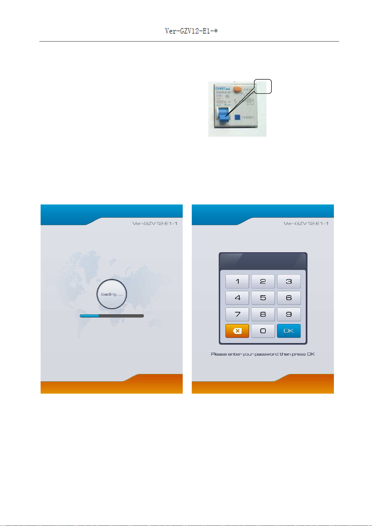
3.9 Start the Equipment
1) Install the handpiece;
2) Water is enough;
3) Connect power line;
4) Turn on electricity breaker′Push A upward″;
5) Emergency switch shall not be pressed down;
6) Press power switch;
7) System enters initialization inter ace (Picture 13);
8) Then system enters password inter ace (Picture 14);
Original password is 123;
9) Input password and system enters main inter ace (Picture 15)
Picture 13 Picture 14
A
Table of contents
Other Body Life Medical Equipment manuals

Popular Medical Equipment manuals by other brands


Getinge
Getinge Arjohuntleigh Nimbus 3 Professional Instructions for use

Mettler Electronics
Mettler Electronics Sonicator 730 Maintenance manual

Pressalit Care
Pressalit Care R1100 Mounting instruction

Denas MS
Denas MS DENAS-T operating manual

bort medical
bort medical ActiveColor quick guide

AccuVein
AccuVein AV400 user manual


