Body Rider BCY6000 User manual

BCY6000
OWNER’S MANUAL
This product is intended for indoor, home use only and is not to be used in a commercial setting.
Indoor Upright Bike with Rear
Drive Flywheel

BCY6000 Page 1
PLEASE KEEP THESE INSTRUCTIONS FOR FUTURE USE & REFERENCE.
DO NOT DISCARD.
WARNING: SERIOUS INJURIES AND EVEN DEATH CAN OCCUR IF THE PROPER SAFETY PRECAUTIONS
ARE NOT FOLLOWED.
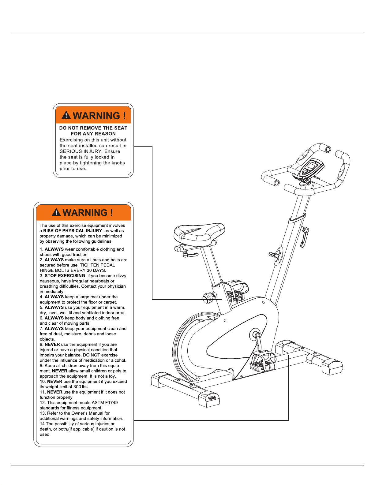
The diagram below highlights and reviews many of the important Safety and Warning labels also found on the unit.
Please ensure any user of the unit familiarizes themselves with this Safety and Warning guidelines before use.

BCY6000 Page 2
Before you undertake any exercise program, please be sure to
consult with your doctor.
Frequent strenuous exercise should be approved by your
doctor and proper use of your product is essential.
Excessive or incorrect training may result in health injuries.
Please read this manual carefully before commencing the
assembly of your product or starting to exercise.
• Please keep all children away from this item when in use.
Do not allow children to climb or play on this item when it
is not in use.
• Supervise teenagers while they use this unit.
• For your own safety, always ensure that there are at least
3 feet of free space in all directions around your product
while you are exercising.
• Regularly check to see that all nuts, bolts and ttings are
securely tightened. Periodically check all moving parts for
obvious signs of wear or damage.
• Any adjustment devices that could interfere with the user’s
movement of this unit should not be left projecting.
• Clean only with a damp cloth, do not use solvent
cleaners. Lubricate the moving parts of your unit every 30
days with a silicone-based grease or product.
If you are in any doubt, do not use your product; contact
CUSTOMER SUPPORT.
• Before use, always ensure that your product is positioned
on a solid, hard-at surface.
• Do not place on carpet. If necessary, use a rubber mat
underneath to reduce the possibility of slipping.
• Always wear appropriate clothing and footwear such as
training shoes when exercising. Do not wear loose clothing
that could become caught in moving parts during exercise.
• Do not use this unit if it is not functioning properly or if it is
not fully assembled.
• Do not use this unit for commercial purposes. This unit is
for home use only.
• Before use, you must read and understand all instructions
& warnings stated in this Owner’s Manual as well as
posted on the equipment.
• It is the facility owner’s responsibility to properly instruct
users on the proper operation of the equipment and to
warn them of the potential hazards.
• If at any time during exercise you feel faint, dizzy or
experience pain, stop and consult your physician.
Your product is intended for use in clean dry conditions. You
should avoid storage in excessively cold or damp places as
this may lead to corrosion and other related problems.
If you have any questions concerning the assembly of your
item or if any parts are missing, please DO NOT RETURN
THE ITEM TO THE STORE OR CONTACT THE
RETAILER.
Our dedicated customer service sta can help you with
any questions you may have regarding the assembly of this
unit and can also mail you replacement parts.
Customer Support is open 9:00 a.m. to 5:00 p.m. (Pacic
Time) Monday through Friday.
Please contact us by any of the following means :
Body Flex Sports, Inc.
21717 Ferrero Parkway, Walnut, CA 91789
Telephone: 1 (888) 266 - 6789
Fax: 1 (909) 598 - 6707
Email: infor@bodyexsports.com
Body Flex Sport warrants your product is free of any defects in
workmanship and materials for a period of 1 year for the frame
and 90 days on all parts if the item is used for the
intended purpose, properly maintained and not used
commercially.
Any alterations or incorrect assembly of the product will void
this warranty.
Proof of purchase must be presented for any warranty
validation (no exceptions). This warranty applies to the original
purchaser only and is not transferable.
This warranty covers parts damaged due to defect in work-
manship and materials; it does not cover abuse or damages
caused during use, storage or assembly. During the warranty
period, Body Flex Sport reserves the right to:
1. provide replacement parts to the purchaser in an eort to
repair the item.
2. repair the product returned to our warehouse
(at purchaser’s cost).
3. replace the product if neither of the two previously
- Ruler with both Metric and English measurements
- 2 x Adjustable Wrenches
- 1 x Philips (”Crosshead”) Screw Driver
Your product is suitable for users weighing:
300 pounds or less
General Information
Safety Storage and Use
Questions
Customer Support
Warranty
Assembling Tools
Weight Limit

BCY6000 Page 3
Before Assembly
1. Take a few minutes to familiarize yourself with the parts and hardware included with your product.
2. The assembly may require two people.
3. Check the frame for any damage and check any wiring (if present) for rips or tears. If you detect damage, rips, or
tears, please contact our Customer Support Team before beginning any assembly.
4. Make sure all the hardware needed is included.
5. It is very important to follow the assembly instructions correctly and to make sure all parts are attached correctly and
rmly tightened when the assembly process is complete.
6. Parts that are not tightened correctly will seem loose and can cause irritating noises and will cause damage to the
equipment.
1. It is only necessary to tighten the bolts and nuts to “nger tight” during the assembly process. This will make it
easier to complete certain steps by allowing more tolerance for all the parts to t properly.
2. Do not tighten all the nuts onto the bolts securely until after you have completed assembly of your product.
3. Use wrenches, pliers, or ratchet and sockets to tighten the bolts and nuts.
4. The Nylon Nut should thread onto the Hex Bolt until the end of the Hex Bolt has passed through the Nylon insert
inside the Nut. Please follow this guideline every time you see this Nylon Nut icon throughout the assembly steps.
Nylon Lock Safety Nuts
Tools Required For Assembly
WARNING
PLEASE NOTE : Many of the parts and hardwares listed on the parts list are already pre-assembled or
installed on the unit.
Tool Description/Purpose
Ruler (with both Metric and English measurements)
QTY: 1
Use to measure the length or size of hardware including
bolts to ensure you are using the correct part.
Adjustable or at wrenches
QTY: 2
Use to securely install parts including nuts and bolts.

BCY6000 Page 4
Part Listing
The following parts list describes all of the parts illustrated in the exploded diagram on the following page.
PLEASE NOTE: most of these parts are already pre-assembled on your unit.
# Description
01 Main Frame
02 Front Stabilizer
03 Rear Stabilizer
04 Head Bolt(M10*20)
05 Spring Washer(D10)
06 Flat Washer(D10)
07 Center Post
08 Pulse Handle Bar
09 Thread Plug Φ13
10 Hex Bolt ST4. 2*20
11 Foam Roller 1
12 End Cap Φ25
13 Hand Pulse Wire
14 Head Bolt M8*16
15 Spring Washer D8
16 Flat Washer D8
17 Foam Roller 2
18 Computer
19 Monitor Support Bracket
20 Center Post Sleeve
21 Sensor Wire
22 Cross Head bolt M5*20
23 Tension
24 Screw ST4.2*16
25 Spring Knob Bolt M16
26 Seat Post Sleeve
27 Seat Post
28 L-Shape Bolt M10
29 Big Flat Washer D10
30 Oval End Cap
31 Nylon Nut M8
32 Flat Washer D8
33 Seat Horizontal Tube
34 Saddle
35L Left Pedal
35R Right Pedal
36L Left Crank
36R Right Crank
37 Crank Cover
38 Nut M10×1.25
39 Shroud Cover
# Description
40L Left Shroud
40R Right Shroud
41 Clasp D20
42 Wavy Washer D20
43 Flat Washer D20
44 Bearing 6004RS
45 Nut M6
46 Hex Bolt M6*20
47 Hex Bolt M6*15
48 Crankshaft Pulley
49 Crankshaft
50 Spring Washer D6
51 Nylon Nut M6
52 Belt
53L Front Left Foot Cap
53R Front Right Foot Cap
54 L-Shape Bolt M16
55 Rear Foot Cap
56 Nylon Nut M10
57 Bushing
58 Idler Wheel
59 Hex Bolt M10*40
60 Spring Φ10×53
61 Thread Plug Φ6
62 Nylon Nut M8
63 Magnet Support
64 Square Magnet 20*20*5
65 Screw M6*10
66 Flat Washer Φ6.5*Φ20*1.5
67 Bearing Bae
68 Bearing 6004RS
69 Bearing Holder
70 Wheel Shaft
71 Hex Bolt M6*20
72 Flywheel
73 Magnetic Wheel
74 Head Bolt M5*10
75 Flywheel Cover
76 Screw ST4.2*10

BCY6000 Page 5
Exploded View
The following diagram is provided to help you familiarize yourself with the parts and hardware that will be used during the
assembly process.
: : Not all of the parts and hardware you see here will be used while you are assembling the machine
because some of these items are already pre-installed. Please use this page only as a reference guide for parts and
hardware.
PLEASE NOTE

BCY6000 Page 6
Hardware and Tool List
Bolts
Washers
Nuts
Others
Tools (Included)
The following hardware is used to assemble your unit. Please take a moment to familiarize yourself with these items.
PLEASE NOTE: Most of these parts are already pre-assembled on your unit. Do not be alarmed if you see parts on this
page that are not included in your hardware packet.
#04
Head Bolt(M10*20) [4 pc]
pre-assembled
#05
Spring Washer(D10) [4 pc]
pre-assembled
#15
Spring Washer D8 [4 pc]
pre-assembled
#31
Nylon Nut M8 [3 pc]
pre-assembled
#25
Spring Knob Bolt M16 [1 pc]
Tools 2
(S13-S14-S15) [1pc]
Tools 1
[1pc]
#54
L-Shape Bolt M16 [1 pc]
#28
L-Shape Bolt M10 [1 pc]
pre-assembled
#06
Flat Washer(D10) [4 pc]
pre-assembled
#16
Flat Washer D8 [4 pc]
pre-assembled
#32
Flat Washer D8 [3 pc]
pre-assembled
#29
Big Flat Washer D10 [1 pc]
pre-assembled
#74
Head Bolt M5*10 [2 pc]
pre-assembled
#76
Screw ST4.2*10 [2 pc]
pre-assembled
#14
Head Bolt M8*16 [4 pc]
pre-assembled

BCY6000 Page 7
Assembly STEP 1
Remove the Head Bolt (04), Spring washer (05) and Flat
Washer (06) that are pre-assembled on the Front Stabilizer
(02) and Rear Stabilizer (03). Then attach the Front
Stabilizer (02) and the Rear Stabilizer (03) to the Main
Frame (01) with the Head Bolt (04), Spring washer (05) and
Flat washer (06).
Hardware Required
NOTE BEFORE STARTING THE ASSEMBLY PROCESS :
To avoid misalignment due to over-tightening, please do not use a
wrench and use only hand-tightening for now to ensure
easy assembly.
Wrench-tightening should be performed after all parts are assembled
to ensure all nuts, bolts, and parts are tightly secured before use. #04
Head Bolt(M10*20) [4 pc]
#05
Spring Washer(D10) [4 pc]
#06
Flat Washer(D10) [4 pc]

BCY6000 Page 8
Assembly STEP 2
Remove the Head Bolt (74) and Screw (76) that are
pre-assembled on the shroud. Then, attach the Flywheel Cover
(75) onto the shroud with the Head Bolt (74) and Screw (76).
Hardware Required
#74
Head Bolt M5*10 [2 pc]
#76
Screw ST4.2*10 [2 pc]

BCY6000 Page 9
Assembly STEP 3
Hardware Required
Lock the Left Pedal (35L) and Right Pedal (35R) to the Left
Crank (36L) and Right Crank (36R) respectively.
Note: the Right Pedal(35R) should be locked CLOCKWISE
and the Left Pedal (35L) should be locked
COUNTER-CLOCKWISE.
Please use drawing below for reference.
The Right Pedal (35R)to the Right Crank (36R) should be
kept in a tight state during the exercise; otherwise, the teeth
of the Right Pedal (35R) to the Right Crank (36R)will be
damaged.
No Hardware Required

BCY6000 Page 10
Assembly STEP 4
Hardware Required
A.
Remove the Flat Washer (32) and Nylon Nut (31) that are
pre-assembled on the Saddle (34). Attach the Saddle (34)
onto the Seat Horizontal Tube (33) with Flat Washer (32)
and Nylon Nut (31).
B.
Remove the pre-installed L-Shape Bolt (28) and
Flat Washer (29) on the Seat Horizontal Tube (33). Insert
and locked the Seat Horizontal Tube (33) onto the Seat Post
(27). Lastly, insert the Seat Post (27) to the opening of the
Main Frame (01), adjust the seat height accordingly and lock it
with Spring Knob Bolt (25).
A
B
#31
Nylon Nut M8 [3 pc]
#32
Flat Washer D8 [3 pc]
#25
Spring Knob Bolt M16 [1 pc]
#29
Big Flat Washer D10 [1 pc]
#28
L-Shape Bolt M10 [1 pc]

BCY6000 Page 11
Assembly STEP 5
Hardware Required
A.
Insert and lock the Center Post (07) onto the Main Frame (01)
with an L-Shape Bolt (54).
B.
Remove the Head Bolts (14), Spring Washer (15), Flat Washer (16)
and the Monitor Support Bracket (19) that are pre-assembled in the
Center Post (07). Then, attached the Pulse Handle Bar (08) to the
Center Post (07) using the Head Bolts (14), Spring Washer (15),
Flat Washer (16) and the Monitor Support Bracket (19).
#54
L-Shape Bolt M16 [1 pc]
#15
Spring Washer D8 [4 pc]
#16
Flat Washer D8 [4 pc]
#14
Head Bolt M8*16 [4 pc]

BCY6000 Page 12
Assembly STEP 7
Hardware Required
THE ASSEMBLY PROCESS IS NOW COMPLETE.
However, for your own safety, please make sure to read this entire Owner’s Manual which
includes safety instructions and warnings, as well as any safety/warning labels axed to the
product before use. For your safety , please visually and functionally inspect and test the unit
after assembly is complete.
Insert the Computer (18) into the Monitor Support bracket(19), then
connect the Sensor Wire (21) and the Hand Pulse Wire (13) to the
back of the Computer (18).
No Hardware Required

BCY6000 Page 13
Computer Operation
MODE
Press this button to select the display function of your
choice.
Hold the button for 3 seconds to reset all value to zero.
Key Function
*IMPORTANT NOTE :
Please remember that the functions in this computer are only meant to be tools to
monitor your workout progress; they are not meant to provide medical information
or be used for medical purposes. Please consult a physician before beginning any
workout program.
SCAN : The monitor will then rotate displaying through the following functions: time,speed,distance,
calories and odometer. Each function will display for 6 seconds.
SPEED : Displays current speed.
DISTANCE : Displays the distance traveled.
TIME : Displays the total amount of time using the machine.
SPEED : Displays current speed.
CALORIES : Displays the amount of calories burned.
ODOMETER : Displays total accumulated distance.
PULSE : Hold the pulse sensor 6-7seconds and read your heart rate per minute.
1. If the display is faint or shows no gures ,please replace the batteries.
2. The monitor will automatically shut o if there is no signal received after 4 minutes .
3. The monitor will auto-power on when exercise and/or motion input is detected.
4. The monitor will automatically start calculating when you start to exercise and will stop calculating when you stop
exercising for 4 minutes .
FUNCTIONS
NOTE
Operation Procedures
Specications
AUTO SCAN Every 6 seconds
TIME 00:00-99:59 min
SPEED Max 999.9 mi./H
CALORIES 0.0-999.9 KCal
ODOMETER 0.0-9999 mi.
DISTANCE 0.0-999.9 mi.
BATTERY TYPE 2 pcs of AAA
PULSE RATE 40-240 bpm
OPERATING TEMP 32°F - 104°F
STORAGE TEMP 14°F - 140°F
FUNCTIONS

BCY6000 Page 14
Computer Operation
NOTES (Regarding the Computer Monitor):
Warning: This device complies with Part 15 of the FCC Rules. Operation is subject to the following two conditions:
(1) This device may not cause harmful interference.
(2) This device must accept any interference received, including interference that may cause undesired operation.
Caution:
This equipment has been tested and found to comply with the limits for a Class B digital device, pursuant to part 15 of the FCC Rules.
These limits are designed to provide reasonable protection against harmful interference in a residential installation. This equipment generates, uses and
can radiate radio frequency energy and, if not installed and used in accordance with the instructions, may cause harmful interference to radio
communications. However, there is no guarantee that interference will not occur in a particular installation. If this equipment does cause harmful
interference to radio or television reception, which can be determined by turning the equipment o and on, the user is encouraged to try to correct the
interference by one or more of the following measures:
- Reorient or relocate the receiving antenna.
- Increase the separation between the equipment and receiver.
- Connect the equipment into an outlet on a circuit dierent from that to which the receiver is connected.
- Consult the dealer or an experienced radio/TV technician for help.
How To Install and Replace Batteries
1. Open the battery door on the back of the computer.
2. The computer operates on two AAA batteries (included).
Refer to the illustration to install or replace the batteries.
NOTE :
1. Do not mix a new battery with an old battery.
2. Use the same type of battery. Do not mix an alkaline
battery with another type of battery.
3. Rechargeable batteries are not recommended.
4. Battery disposal should be handled according to all state
and federal laws and regulations.
5. Do not dispose of batteries in re.

BCY6000 Page 15
Safety and Maintenance
• Make sure all nuts, bolts, and screws are tightened prior to use.
• Be sure that all adjustment locking devices and safety devices are properly engaged prior to use!
• Never over-tighten the above-mentioned devices and parts to avoid damage to the unit.
• Check for loose parts and components and make proper adjustments prior to use.
• Check to see if there are any tears or bends in the welding or metal prior to use. If tears or bends are found,
DO NOT use the unit and contact our CUSTOMER SUPPORT.
•Extreme care must be taken to not allow your feet, ngers, hair, clothing, and/or any loose items to be snagged into
any portion of the bike when the unit is in motion. Failure to follow these instructions could result in serious injury,
including the loss of ngers.
• Always wait for the pedals and other moving parts (which can gain great momentum during riding) to come to a
complete stop before dismounting the unit to avoid serious injury.
• Please review all safety instructions and warnings in this entire Owner’s Manual, as well as any safety/warning labels
axed to the product before use.
•To avoid rust or corrosion to the ywheel caused by moisture and sweat, we advise wiping and drying the ywheel
and surrounding parts with a dry absorbent towel after each workout session.
• Do not use solvent cleaners. If you are in any doubt, do not use your cleansing product and contact CUSTOMER
SUPPORT.
•When the bike is not in use, the resistance should be left loose, NOT tightened down against the ywheel. You can
do this with the easy-to-adjust tension knob. This will ensure longer life of the Friction Belt. mechanism from working
properly. Please contact our CUSTOMER SUPPORT if you have questions regarding the cleaning of your bike.
•The specic Parts on your unit which may see possible signs of wear after prolonged use are listed as
follows (please check these parts before each use):
L-Shape Bolts (28), Left/Right Pedals (35L/35R), Spring Loaded Knob (25 ).
• For any replacement warning labels, please contact our CUSTOMER SUPPORT at
1 (888) 266-6789 or 1 (909) 598-9876, or mail in a written request to:
Body Flex Sports, Inc.
21717 Ferrero Parkway
Walnut, CA 91789
More detailed information about how to reach our CUSTOMER SUPPORT may be found on Page 2 of the
Owner’s Manual under the “CUSTOMER SUPPORT” section.
Safety & Warning
Maintenance & Care

BCY6000 Page 16
Troubleshooting
If the computer is not displaying the CALORIES/DISTANCE/TIME/(ETC.)
functions (or you are getting inaccurate readings), please adjust
the following:
1. Check to ensure all computer sensor wires are properly
connected and are not damaged.
2. You may need to refer to installation/assembly directions for the sensor
wires in this manual.
If the computer display is blank & not displaying any data (or does not
appear to power on), please adjust the following:
1. Check to ensure all sensor wires are all properly connected and are not
damaged.
2. Check to ensure the AC Adapter* or Batteries* are properly plugged in or
fully charged.
3. Check your product manual to determine if your model uses either AC
Adapter or batteries to power your unit.
If the computer is not picking up your hand pulse signal (or you are getting
inaccurate readings), please adjust the following:
1. Slightly moisten/dampen the palms with water so the sensors can detect
a pulse signal.
2. Do not grip the sensors too tightly. Only moderate pressure need be
applied.
3. Gripping the sensors too tightly restricts and seizes detection of your
pulse.
4. Remove any rings or jewelry to prevent interference.
5. Check to ensure all pulse sensor wires are properly connected and are
not dam-aged.
6. You may need to refer to installation/assembly directions for the pulse
sensor wires in this manual.
(AFTER COMPLETE ASSEMBLY)
Troubleshoot Area
Calories/Distance/
Time (Etc.)
Computer Display
Hand Pulse Signal
Solution

BCY6000 Page 17
Warm-Up Instructions
1. Sit with your knees exed and
soles of feet together.
2. Hold your ankles and bend
at your hips (keep your back
straight) as you press your
knees toward the oor with your
elbows.
1. Lie on your back and raise
your right leg as you clasp both
hands under the back of the
knee. Keep your left leg straight.
2. Gently pull your right leg toward
your trunk without
raising your upper body. Switch
leg positions and repeat.
1. Sit with your left leg extended
and bend your right leg at the
knee as you place the sole of
your right foot against the inner
thigh of your extended leg.
2. Flex the foot of your extended
leg (toes pointed toward
ceiling) and gently bend forward
from your hips; keep your back
straight.
3. Reach your hands on your
extended leg as far as possible
and then switch legs and repeat.
1. Assume the depicted position on your hands and knees. Stretch your
hands out in front of you and then slowly start to pull them back in toward
your body as you tuck your chin and arch your back upward.
2. Return to the starting position slowly.
1. Sit with your leg extended and
bend your right knee as you
cross your right leg over your
left leg. Your right foot of your
extended leg foot should be at
on the oor alongside your left
knee.
2. Place your left arm on the
outside of your right leg and pull
against that leg while twisting
your trunk as far as possible to
the right. Place your right hand
on the oor behind your but-
tocks. Reverse leg positions and
repeat.
Before use, you must read and understand all instructions & warnings stated in this Owner’s Manual as well as posted
on the equipment. Before beginning any exercise program including the following exibility exercises, please consult with
your physician.
The following exibility exercises are provided to you as a means to prevent injury while you are exercising. A proper
warm-up routine decreases the chance of injuring your muscles while you are exercising. Please take the time to do these
exibility exercises before and after each time you exercise.
Groin Stretch
Groin Stretch
Hamstring Stretch
Trunk Flexion, Prone
Trunk Twister

BCY6000 Page 18
Warm-Up Instructions
1. Bring your right hand over your
right shoulder to the
upper back and bring your left
hand under your left shoulder to
the upper back.
2. Try to reach your ngertips. If
you are not able to reach your
ngertips, use a towel as an
extension of your hands and
gently pull one hand toward the
other.
Reverse arm positions and
1. Stand on your left leg and hold
onto a support with your left
hand.
2. Flex your right leg behind you,
grasp your ankle or foot with
your right hand and pull your
foot toward your buttocks. Keep
your back straight and right
knee pointed down.
Repeat on the other leg.
1. Place both hands against a wall
to aid your balance. Press the
ball of your left foot against the
wall and keep the heel of the
same foot rested on the oor
(make sure your left knee is
bent).
2. Slowly start to straighten your
left knee and you will feel the
muscles in your left calf stretch.
Switch leg positions and repeat.
Shoulder Stretch Quadriceps Stretch Calf Twister

THANK YOU FOR YOUR PURCHASE
MODEL NO.: BCY6000
Please ll in the information below and keep this manual
along with your sales receipt as proof of purchase.
Serial Number :
Date of Purchase :
Retailer :
Body Flex Sports, Inc.
21717 Ferrero Parkway
Walnut, CA 91789
Phone: 1 (888) 266-6789
Fax : 1 (909) 598-6707
Email : info@bodyexsports.com
Ver. 07/09/2019 Printed in China
Table of contents
Other Body Rider Exercise Bike manuals