Body Rider XRB271 User manual
OWNER’S MANUAL
* This item is for consumer use only and it is not meant for commercial use.
Deluxe Folding Bike
XRB271 / XRB261
XRB271 Page 1
General Information
Warranty
Body Flex Sports warrants your product for
a period of 1 year for the frame and 90 days
on all parts if the item is used for the intended
purpose, properly maintained and not used
commercially. Any alterations or incorrect
assembly of the product will void this warranty.
Proof of purchase must be presented for any
warranty validation (no exceptions). This
warranty applies to the original purchaser only
and is not transferable.
This warranty does not cover abuse or defects
caused during use, storage or assembly.
During the warranty period, Body Flex Sports
reserves the right to:
a). provide replacement parts to the
purchaser in an effort to repair the item.
b). repair the product returned to our
warehouse (at the purchaser’s cost).
c). replace the product if neither of the two
previously mentioned actions effect repair.
This warranty does not cover normal wear and
tear on upholstery.
Questions
If you have any questions concerning the
assembly of your item or if any parts are
missing, please DO NOT RETURN THE
ITEM TO THE STORE OR CONTACT THE
RETAILER. Our dedicated customer service
staff can help you with any questions you may
have regarding the assembly of this unit and
can also mail you replacement parts.
Customer Support
Customer Support is open 9:00 a.m. to 5:00
p.m. (Pacific Time) Monday through Friday.
Please contact us by any of the following
means.
Body Flex Sports, Inc.
21717 Ferrero Parkway, Walnut, CA 91789
Telephone: (888) 266 - 6789
Fax: (909) 598 - 6707
Email: info@bodyflexsports.com
Safety
Before you undertake any exercise program,
please be sure to consult with your doctor.
Frequent strenuous exercise should be
approved by your doctor and proper use
of your product is essential. Excessive or incorrect
training may result to health injuries. Please read
this manual carefully before commencing the
assembly of your product or starting to exercise.
• Please keep all children away from this item
when in use. Do not allow children to climb or
play on them when they are not in use.
• Supervise teenagers while they use this unit.
• For your own safety, always ensure that there
is at least 3 feet of free space in all directions
around your product while you are exercising.
• Regularly check to see that all nuts, bolts and
fittings are securely tightened. Periodically
check all moving parts for obvious signs of
wear or damage.
• Clean only with a damp cloth, do not use
solvent cleaners. If you are in any doubt, do
not use your product; contact CUSTOMER
SUPPORT.
• Before use, always ensure that your product
is positioned on a solid, flat surface. If
necessary, use a rubber mat underneath to
reduce the possibility of slipping.
•Always wear appropriate clothing and
footwear such as training shoes when
exercising. Do not wear loose clothing that
could become caught in moving parts during
exercise.
• Do not use this unit if it is not functioning
properly or if it is not fully assembled.
• Do not use this unit for commercial purposes.
This unit is for home use only.
Storage and Use
Your product is intended for use in clean
dry conditions. You should avoid storage in
excessively cold or damp places as this may
lead to corrosion and other related problems.
Weight Limit
Your product is suitable for users weighing:
250 pounds or less.
• Before use, you must read and understand all
instructions & warnings stated in this Owner’s
Manual as well as posted on the equipment.
• It is the facility owner’s responsibility to properly
instruct users on the proper operation of the
equipment and to warn them of the potential
hazards.
• If at any time during exercise you feel faint, dizzy
or experience pain, stop and consult your
physician.
Assembling Tools
- Ruler with both metric and English measurements
- 2 x Adjustable Wrenches
- 1 x Philips (”Crosshead”) Screw Driver
•
Any adjustment devices that could interfere with
the user's movement on this unit should not be
left projecting.
XRB 271 Page 2
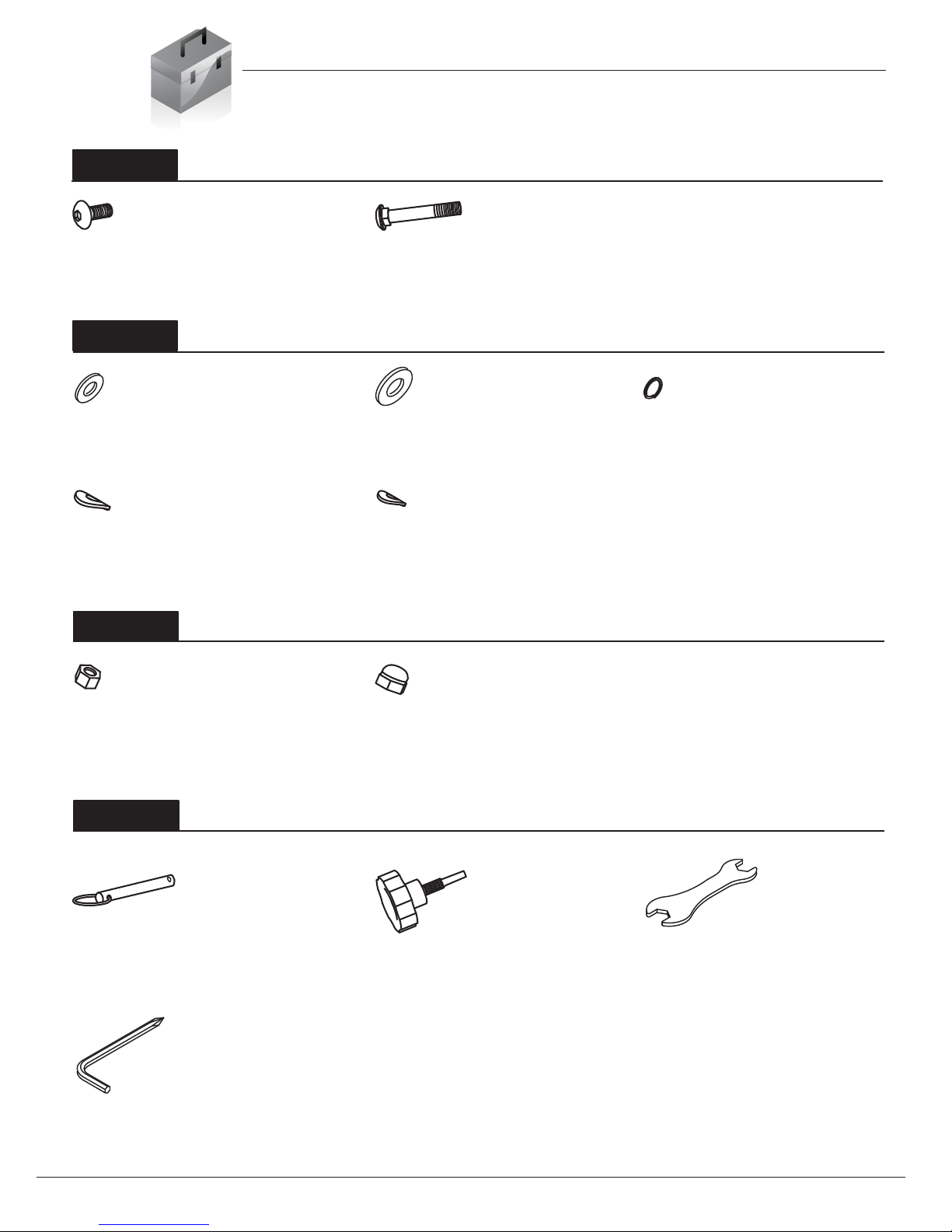
Hardware List
The following hardware is used to assemble your unit. Please take a moment to familiarize yourself with these
items. Please note some of this hardware is already pre-assembled on the machine. Do not be alarmed if you
see parts on this page that are not included in your hardware packet
#17. Bolt (M6x12 mm)
[4 Pieces]
#20. Carriage Bolt (M8x60 mm)
[4 Pieces]
#22. Washer (M6)
[2 Pieces]
#25. Washer (M8)
[3 Pieces] Pre-assembled
#26. Spring Washer (M6)
[4 Pieces]
#27. Arc Washer (M8)
[4 Pieces]
#28. Arc Washer (M6)
[2 Pieces]
#29. Nylon Nut (M8)
[3 Pieces] Pre-assembled
#30. Nut (M8)
[4 Pieces]
#15. Pop Pin (M8x70 mm)
[1 Piece]
#32. Knob Bolt (M12x45.5 mm)
[1 Piece]
#43. Wrench 1
[1 Piece]
#44. Wrench 2
[1 Piece]
Bolt
Others
Nut
Washer

Page 3
Parts Listing
The following parts list describes all of the parts illustrated on the
exploded diagram on the following page. Please note, most of
these parts are already pre-assembled on your unit.
XRB 271
Part# Description Part# Description
01 Shroud Frame 28 Arc Washer (M6)
02 Main Frame 29 Nylon Nut (M8)
03 Seat Post 30 Nut (M8)
04 Handlebar 31 Flange Nut (M10)
05 Stabilizer 32 Knob Bolt (M12x45.5 mm)
06 Left Crank 33 Wire Plug (φ20)
07 Right Crank 34 Bumper
08 Left Pedal 35 Adhesive
09 Right Pedal 36 Bushing
10 Axis 37 Seat Post Sleeve (38-30)
11 Seat 38 Crank Cover (M22)
12 Monitor 39 Round Outer End Cap (50 mm)
13 Monitor Base 40 Handlebar Foam
14 Tension Controller 41 Round Inner End Cap (25 mm)
15 Pop Pin (M8x70 mm) 42 Wire Plug (φ12)
16 Screw (M8x15 mm) 43 Wrench 1
17 Bolt (M6x12 mm) 44 Wrench 2
18 Screw (M5x8 mm) 45 Monitor Wire (Upper)
19 Screw (ST4.2x20 mm) 46 Monitor Wire (Lower)
20 Carriage Bolt (M8x60 mm) 47 Hand Pulse Wire (Upper)
21 Screw (M5x20 mm) 48 Hand Pulse Wire (Lower)
22 Washer (M6) 49 Handle Pulse Sensors
23 Washer (M5) 50 Left Shroud
24 Washer (M8) 51 Right Shroud
25 Washer (M8) 52 Shroud Cover
26 Spring Washer (M6)
27 Arc Washer (M8)

Page 4
Exploded Diagram
The following diagram is provided to help you familiarize yourself with the parts and
hardware that will be used during the assembly process. Please note that not all of the
parts and hardware you see here will be used while you are assembling the machine
because some of these items are already pre-installed. Please continue to the next
page to begin the assembly process and use this page only as a reference guide for
parts and hardware.
XRB 271
Assembly Instructions
Page 5
Hardware Required
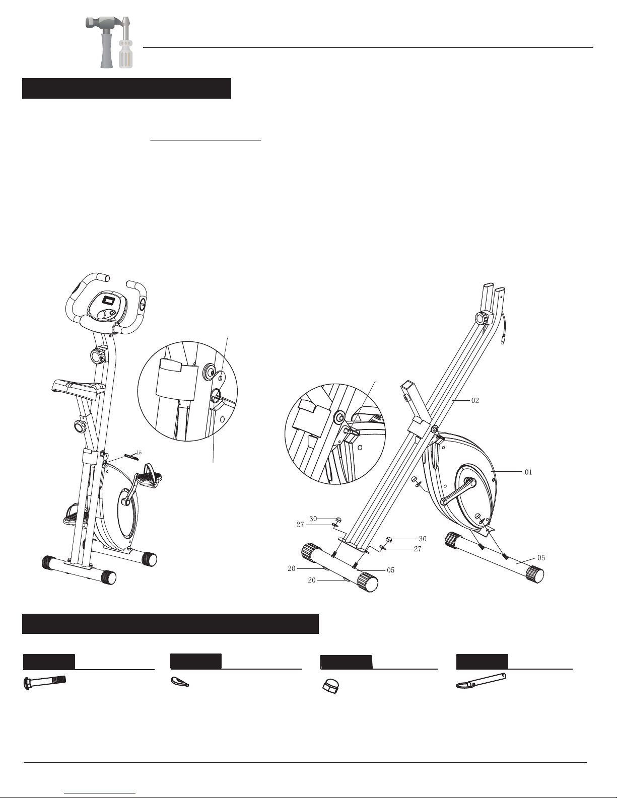
A.) Remove the Pop Pin (#15) that is pre-assembled through the lower hole of the Shroud Frame (#01). Then,
insert it into the upper hole located on the Shroud Frame (#01) until it passes through and clicks into place. For your
safety, thisPop Pin (#15) MUST remain inserted whenever the unit is in use OR if it is left unfolded and/or unattended.
After you complete proper assembly, you will be able to fold the unit for storage. Please follow the instructions below
for more details:
FOLDING INSTRUCTIONS (to store the unit):
To fold your unit simply remove the Pop Pin (#15) from the upper hole on the Shroud Frame (#01), fold the unit and
then insert Pop Pin (#15) to the lower hole of the Shroud Frame (#01) until pass through, ensuring the Pop Pin (#15)
locks into place.
B.) Attach the two Stabilizers (#05) to the Shroud Frame (#01) and Main Frame (#02) with four Carriage Bolts (#20),
four Arc Washers (#27) and four Nuts (#30).
Note:
Prior to beginning assembly, it is
necessary to remove the Pop Pin
(#15) from the Shroud Frame
(#01) in order to open the Frame
as illustrated below.
#20. Carriae Bolt (M8x60 mm)
[4 Pieces]
#27. Arc Washer (M8)
[4 Pieces] #30. Nut (M8)
[4 Pieces]
#15. Pop Pin (M8x70 mm)
[1 Piece]
Bolt Others
Nut
Washer
A s s e m b l y S t e p 1
XRB 271
NOTE: Folding your unit is inteded to allow you to store it when not in use.
UPPER HOLE
PIN SHOWN LOCKED IN
LOWER HOLE
PIN SHOWN LOCKED IN
UPPER HOLE
Page 6
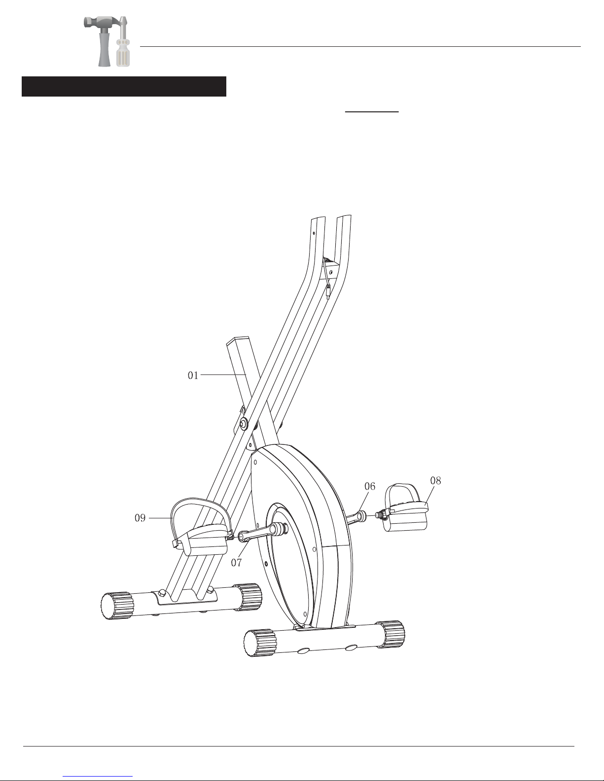
A.Secure Left Pedal (#08) onto the Left Crank (#06) by turning it COUNTER-CLOCKWISE.
You will need to use a Wrench to tighten if necessary.
B.Secure Right Pedal (#09) onto the Right Crank (#07) by turning it CLOCKWISE.
You will need to use a Wrench to tighten if necessary.
A s s e m b l y S t e p 2
XRB 271
Assembly Instructions

Page 7
A s s e m b l y S t e p 3
Hardware Required
Remove the Washers (#25) and Nylon Nuts (#29) that are pre-assembled on the Seat (#11), and set them aside
for now.
Attach the Seat (#11) to the Seat Post (#03) using a total of three Washers (25) and three Nylon Nuts (#29) that were
previously removed and set aside.
Slide the Seat Post (#03) into the Shroud Frame (#01) with the holes facing each other. Screw Knob Bolt (#32)
through the Shroud Frame (#01)
and through the hole located on the Seat Post (#03) that best accommodates
XRB 271
#25. Washer (M8)
[3 Pieces]
#29. Nylon Nut (M8)
[3 Pieces]
#32. Knob Bolt (M12x45.5 mm)
[1 Piece]
Others
Nut
Washer
Assembly Instructions
your height and screw snugly.

Page 8
A s s e m b l y S t e p 4
A.) Attach Handlebar (#04) to the Main Frame (#02), AND secure them together by using two Bolts (#17),
two Spring Washers (#26) and two Washers (#22) from the sides, and two Bolts (#17), two Spring
Washers (#26) and two Arc Washers (#28) from the front.
B.) Connect the Monitor Wire (Upper) (#45) to the Monitor Wire (Lower) (#46) as shown in the
illustration below. ASSEMBLY IS NOW COMPLETE. HOWEVER, PLEASE READ ALL SAFETY
GUIDELINES & WARNING LABELS BEFORE USING THE UNIT TO AVOID SERIOUS INJURY.
Hardware Required
XRB 271
#17. Bolt (M6x12 mm)
[4 Pieces]
#22. Washer (M6)
[2 Pieces] #26. Spring Washer (M6)
[4 Pieces] #28. Arc Washer (M6)
[2 Pieces]
Bolt
Washer
Assembly Instructions

Safety Instructions / Computer Operation
Page 9
SAFETY INSTRUCTIONS
•Make sure all nuts/bolts are securely (but not over) tightened.
•Check for loose parts and components prior to each use.
•Check to see if there are any tears or bends in the welding or metal. Do NOT use the unit if any are
present. Please call our Customer Service Department for assistance.
•Be sure that all adjustment and locking devices and safety devices are properly engaged prior to use!
MODE SPECIFICATIONS:
XRB 271
TIME…………………………………………………………………………… 0:00 - 99:99 (Minutes)
SPEED………………………………………………………………..………. - 99.9 (Miles Per Hour)
DISTANCE…………………………..….……………………………......... 0 - 999.9 (Miles)
CALORIES .……………...…….….............………………................ - 9999 (Calories)
PULSE ……………......……………………………………………………....40 - 240 (Beats Per Minute)
OPERATION PROCEDURES:__________________________________________________
0
0
1. Auto On/Off:
The system will turn on when the main BUTTON is pressed or when mo on on the unit is detected
The system will turn offautoma er approximately 4 minutes if the main BUTTON is not pressed or
no on the unit is detected.
2. Reset: The unit can be reset by either changing
3. Display: To choose between "SCAN" or “(locked) MODE”, press the main BUTTON
every 4 seconds.
MODES:
1. TIME:
2. SPEED(RPM):
3. DISTANCE:
4. CALORIE:
S:
5. ODOMETER:
6. PULSE:
7. SCAN:
Pr
displaying once the unit detects pedaling.
COMPUTER MONITOR INSTRUCTIONS
will display on the screen.
display once the unit detects pedaling.
hands on the pulse sensors on the handlebar. Grip the pulse sensors lightly and hold for about 30 seconds for an
accurate reading. A number will display, showing your pulse reading.
Baeries may be replaced at the back of the Computer Monitor.
Thanks for choosing
XRB 271
version: 2-10-2012
Store Location:
XRB 271

Body Flex Sports, Inc. • 21717 Ferrero Parkway, Walnut, CA 91789 • Telephone: (888) 266 - 6789 • Email: info@bodyexsports.com
This manual suits for next models
1
Table of contents
Other Body Rider Exercise Bike manuals


Popular Exercise Bike manuals by other brands


Sunny Health & Fitness
Sunny Health & Fitness SF-B121021 user manual

Monark
Monark 827E instruction manual

Stamina
Stamina 1310 owner's manual

American Fitness
American Fitness SPR-BK1072A owner's manual
 Service manual")
Cateye
Cateye CS-1000 (CYCLO SIMULATOR) Service manual

BH FITNESS
BH FITNESS H9158H Instructions for assembly and use