Body Rider XRB3535 User manual

BODYR~
[*
VIP
Access
Pass
]
LEISA
HART
flTNESS
HUB
FREE Trio Trainer
Workouts
Hart
DVD
Library
Access
Lifestyle
Tips & Recipes
Email &
Chat
Support
Enjoy yourVIP Benefits in
the
HART FITNESS HUB!
Scan
QR Code Now!
OR
Visit:
www.LeisaHart.com/cardiocycle
All you need
is
A
FREE
"QR Code Reader"
App
or
your phone ordevice!
1. Go
to
yourApp Store
2. Choose & download
FREE
App
3. SCAN CODE &
GET
STARTED!
This product
is
intended for indoor, home use only and
is
not to
be
used
in
a commercial setting.
~~--,\~
..
oWNER'S
MANUAL
'<Lt!.~1'{~-"'..
. .

PLEASE KEEP THESE I
NSTRUCT
I
ONS
FOR
FUTURE USE & REFERENCE.
DO NOT DISCARD.
WARNING: SERIOUS INJURIES AND EVEN DEATH CAN OCCUR
IF
THE PROPER SAFETY PRECAUTIONS
ARE NOT FOLLOWED.
The diagram below highlights and reviews many of the important Safety and Warning labels also found
on
the unit.
XRB3535
Please ensure any user of the unit familiarizes themselves
with
these Safety and Warning guidelines before use.
WARNINGI
DO
NOT
REMOVE
T
HE
SEAT
FOR
ANY
REASON
Ex
er
cisi
ng
on
th
is
un
it
w
ith
out
the
sea
t
in
sta
ll
edc
an
res
ult
in
S
ERI
OUS
INJUR
Y.
En
s
ur
et
he
seat
is
full
y
loc
k
ed
in
pl
a
ce
byt
igh
te
nin
g
th
e
kn
obs
pr
io
r
to
use.
WARNINGI
T
he
u
se
of
th
is
exe
rcisee
quipm
ent
in
v
olv
es
a
RI
SK
OF
PHY
SI
CAL
INJU
RY
as
we
ll
as
p
rop
erty
damage,
wh
i
ch
can
be
m
in
imize
dby
observi
ngthe
fo
l
lowi
ng
gu
id
eli
n
es:
1.
AL
W
AYS
wear
com
f
ortab
le 8.
NEV
ER
use
the
equi
pm
ent
cl
ot
h
ing
and
sh
oes
w
it
h
good
if
you
are
in
ju
r
ed
or
have
a
tr
act
ion.
physic
al
condition
that
impairs
2.
A
LW
AYS
ma
ke
su
re
a
ll
you
r
balance.
DO
NOT
exerc
i
se
nuts
and
bo
l
ts
are
secure
d un
de
rthei
nf
l
ue
n
ce
of
b
ef
ore
u
se.
TI
GH
TE
N
PE
DA
L
medicat
i
on
or
al
co
ho
l.
HIN
GE
BO
L
TS
EVERY
30
DAYS
.
9.
Keep
all
children
away
from
3.
STO
P
EX
ERC
IS
ING
if
you
this
equ
ip
men
t.
NEVER
a
ll
ow
bec
om
edi
zzy
,
na
u
se
ou
s,
h
ave
sma
ll c
hi
l
dr
enorp
ets
to
ir
reg
u
lar
hea
rb
eats
or
approach
the
equi
pme
n
t.
It
is
br
ea
thi
ng
di
ff
i
cu
l
ties
.
Contact
no
t a
toy.
yo
ur p
hys
iciani
mm
e
diat
ely.
10.
NEVER
use
the
eq
uip
men
t
4.
A
LWA
YS
keep
a
la
r
ge
m
at
if
yo
u
excee
dits
weig
ht
li
mit
of
unde
rthee
qu
ipmen
t
to
pro
t
ect
250
lbs
.
thef
lo
ororc
arp
e
t.
11.NE
VER
u
se
t
he
equ
ip
ment
5.A
LWAY
Su
se
yo
ur
if it
d
oes
not
function
pro
per
ly.
eq
uipm
e
nt
in
a
warm
,
dry,
12.
Th
is
equipme
nt
mee
ts
leve
l,w
ell
-
lit
a
nd
ve
ntil
ated
AS
TM
F1
7
49
standa
rd
s
for
in
door
area.
fi
tness
e
quipm
e
nt.
6.
ALWAYS
k
ee
pbodyand
13
.Refer
to
the
Owne
r
's
clo
thin
g
free
and
cle
ar
of
Man
ualfora
ddit
iona
l
warni
n
gs
m
ovi
ng
pa
rt
s.
an
ds
af
ety
i
nformat
ion.
7.
ALWAYS
ke
epy
our
14
.
The
p
ossibil
i
ty
of
ser
ious
equ
ipm
ent cl
ea
n
an
dfr
ee
of
inj
uri
es
or
d
eat
h,or
bot
h(if
d
ust,
mo
i
st
u
re,
d
eb
r
is
an
d
ap
p
licab
l
e)
if
ca
ut
ion
isn
ot
loo
se
obj
e
cts.
u
sed.
Page 1

General Information
Safety
Before you undertake
any
exercise program, please be sure to
consult
with
your
doctor.
Frequent
strenuous
exercise should be
approved
by
your
doctor
and
proper
use
of
your
product is essential.
Excessive
or
incorrect training
may
result to health injuries.
Please read this
manual
carefully before
commencing
the
assembly
of
your
product
or
starting to exercise.
Please keep all children
away
from
this item
when
in
use.
Do
not
allow
children to climb
or
play on this item
when
it
is
not
in use.
Supervise
teenagers
while
they
use this unit.
For
your
own
safety, always ensure that there is
at
least
3 feet
of
free
space
in
all directions around
your
product
while you are exercising.
Regularly
check
to
see
that all nuts, bolts and fittings are
securely
tightened. Periodically
check
all moving parts
for
obvious
signs
of
wear
or
damage.
Any
adjustment
devices that could interfere with
the
user
's
movement
on this unit should
not
be left projecting.
Clean only with a
damp
cloth,
do
not
use solvent
cleaners. Lubricate the moving parts
of
your
unit every 30
days
with a silicone-based
grease
or
product.
If you are
in
any
doubt, do not
use
your
product; contact
CUSTOMER
SUPPORT.
Before use,
always
ensure that
your
product is positioned
on a solid, hard-flaLsurface.
Do
not
place on carpet. If
necessary
, use a
rubber
mat
underneath
to reduce the possibility
of
slipping.
Always
wear
appropriate clothing and
footwear
such as
training
shoes
when
exercising. Do
not
wear
loose clothing
that
could
become
caught
in
moving parts during exercise.
Do
not
use this unit
if
it is not functioning properly
or
if
it is
not fully
assembled
.
Do
not
use this unit
for
commercial
purposes
. This unit is
for
home
use only.
Before use, you
must
read and understand all instructions
& warnings stated
in
this
Owner's
Manual
as well as post-
ed on
the
equipment.
It is
the
facility
owner
's responsibility
to
properly instruct
users on the
proper
operation
of
the
equipment
and to
warn them
of
the
potential hazards.
If at
any
time
during exercise you feel faint,
dizzy
or
experience pain, stop and consult
your
physician.
Assembling Tools
-Ruler with both Metric and English
measurements
- 2 x Adjustable
Wrenches
- 1 x Phillips ("Cross-head") Screw Driver
Weight Limit
Your
product
is suitable
for
users weighing :
250
pounds
or
less
XRB3535
Storage and Use
Your
product
is intended
for
use
in
clean
dry
conditions. You
should avoid
storage
in
excessively
cold
or
damp
places as
this
may
lead to corrosion and
other
related
problems
.
Warranty
Hupa
International warrants
your
product
for
a period
of
1
year
for
the
frame
and 90
days
on all parts
if
the item is used
for
the intended purpose, properly maintained and not used
commercially.
Any
alterations
or
incorrect
assembly
of
the
product
will void
this
warranty
.
Proof
of
purchase
must
be presented for
any
warranty
validation (no exceptions).
This
warranty applies to the original
purchaser
only
and is
not
transferable.
This
warranty
does
not
cover
abuse
or defects
caused
during
use, storage
or
assembly. During the warranty period, Hupa
International reserves
the
right to:
1. provide replacement parts
to
the
purchaser
in an effort to
repair
the
item.
2. repair
the
product returned to
our
warehouse
(at the
purchaser
's cost).
3. replace the
product
if neither
of
the
two
previously
mentioned
actions effect repair. This
warranty
does
not
cover
normal
wear
and
tear
on upholstery.
Questions
If you
have
any
questions
concerning the
assembly
of y
our
item
or
if
any
parts are missing, please DO NOT RETURN
THE ITEM TO THE STORE OR CONTACT THE
RETAILER.
Our
dedicated
customer
service staff can help you with
any
questions
you
may
have
regarding the
assembly
of
this
unit and can also mail you replacement parts.
Customer Support
Customer
Support
is open 9:00 a.m. to 5:00 p.m. (Pacific
Time)
Monday
through Friday.
Please
contact
us
by
any
of
the
following
means
:
Hupa International, Inc.
21717 Ferrero
Parkway
,
Walnut
,
CA
91789
Telephone: 1 (888)
266
-
6789
Fa
x:
1 (
909)
598 -
6707
Email:
Page 2
Before Assembly
A WARNING
1.
Take a few minutes
to
familiarize yourself with the parts and hardware included with your product.
2. Assembly may require two people.
3. Check the frame for any damage and check any wiring (if present) for rips or tears. If you detect damage, rips, or
tears, please contact our Customer Support Team before beginning any assembly.
4.
Make sure all the hardware needed
is
included.
5. It
is
very important to follow the assembly instructions correctly and to make sure all parts are attached correctly and
firmly tightened when the assembly process
is
complete.
6.
Parts that are not tightened correctly will seem loose and can cause irritating noises and will cause damage to the
equipment.
PLEASE NOTE : Many of the parts and hardwares listed
on
the parts list are already pre-assembled or
installed
on
the unit.
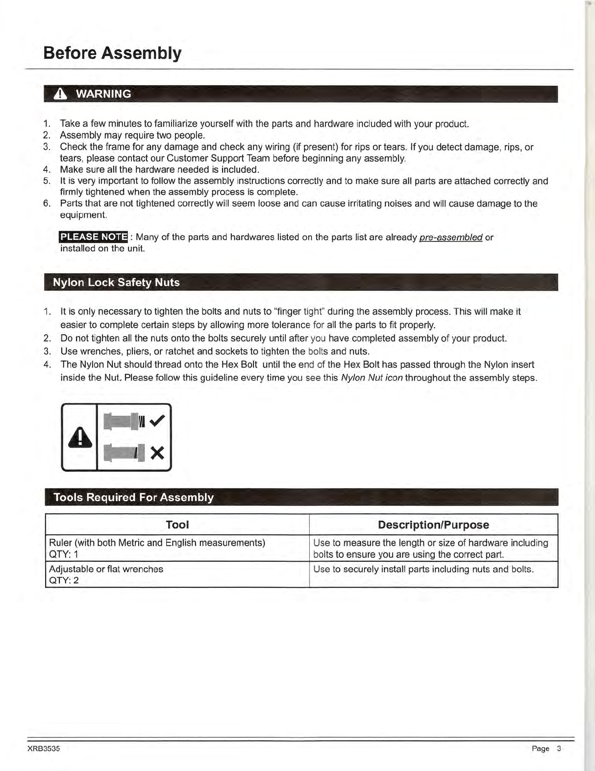
Nylon Lock Safety Nuts
1.
It
is
only necessary
to
tighten the bolts and nuts to "finger tight" during the assembly process. This will make it
easier to complete certain steps by allowing more tolerance for all the parts to
fit
properly.
2.
Do
not tighten all the nuts onto the bolts securely until after y
ou
have completed assembly of your product.
3.
Use wrenches, pliers, or ratchet and sockets to tighten the bolts and nuts.
4. The Nylon Nut should thread onto the Hex Bolt until the end of the Hex Bolt has passed through the Nyl
on
insert
inside the
Nut
Please follow
th
is guideline every time you see this Nylon Nut icon throughout the assembly steps.
Tools Required For Assembly
Tool Description/Purpose
Ruler (with both Metric and English measurements) U
se
to measure the length or size of hardware including
QTY:
1 bolts to ensure you are using the correct part.
Adjustable or flat wrenches Use to securely install parts including nuts and bolts.
QTY: 2
XRB3535 Page 3

Part Listing
The following parts list describes all of the parts illustrated on the exploded diagram
on
the following page.
PLEASE NOTE : most of these parts are already pre-assembled on your unit.
# Description # Description
01
Shroud Frame 27 Screw (M5x20 mm)
02 Main Frame 28 Washer (M5)
03 Front Stabilizer 29 Bolt (M8x15 mm)
04 Rear Stabilizer 30 Washer (M8)
05 Seat Cushion Tube
31
Bushing
06 Handlebar 32 Axle
07 Cushion Support Tube 33 Nylon Nut (M8)
08 Backrest Cushion Tube 34 Carriage Bolt (M8x50mm)
09 Rear Handlebar 35 Square End Cap
10 Sleeve 36 Bolt (M8x75 mm)
11
Knob Bolt 37 Square End Cap
12
Arc Washer (M8) 38 Bolt (M8x45 mrii)
13 Cap Nut (M8) 39 Spring Washer (M8)
14L/R End Cap for Front Stabilizer 40 Backrest Cushion
15 Screw (ST4
.2
x18 mm)
41
Monitor Wire
16 Bolt (M6x10 mm) 42L/R Left/Right Crank
17 Spring Washer (M6) 43L/R Left/Right Pedal
18 Handlebar Foam 44L/R Left/Right Nylon Nut
19 Round End Cap 45 Lock-pin
20 End Cap for Rear Stabilizer 46 Bushing
21
Monitor 47 Cell Phone Base
22 Seat Cushion 48 Bolt (M8x40 mm)
23 Washer (M8) 49 Rear Handlebar Foam
24 Nylon Nut 50 Bump
25 Wire Plug
51
Pulse Sensor
26 Tension Controller
XRB3535 Page 4
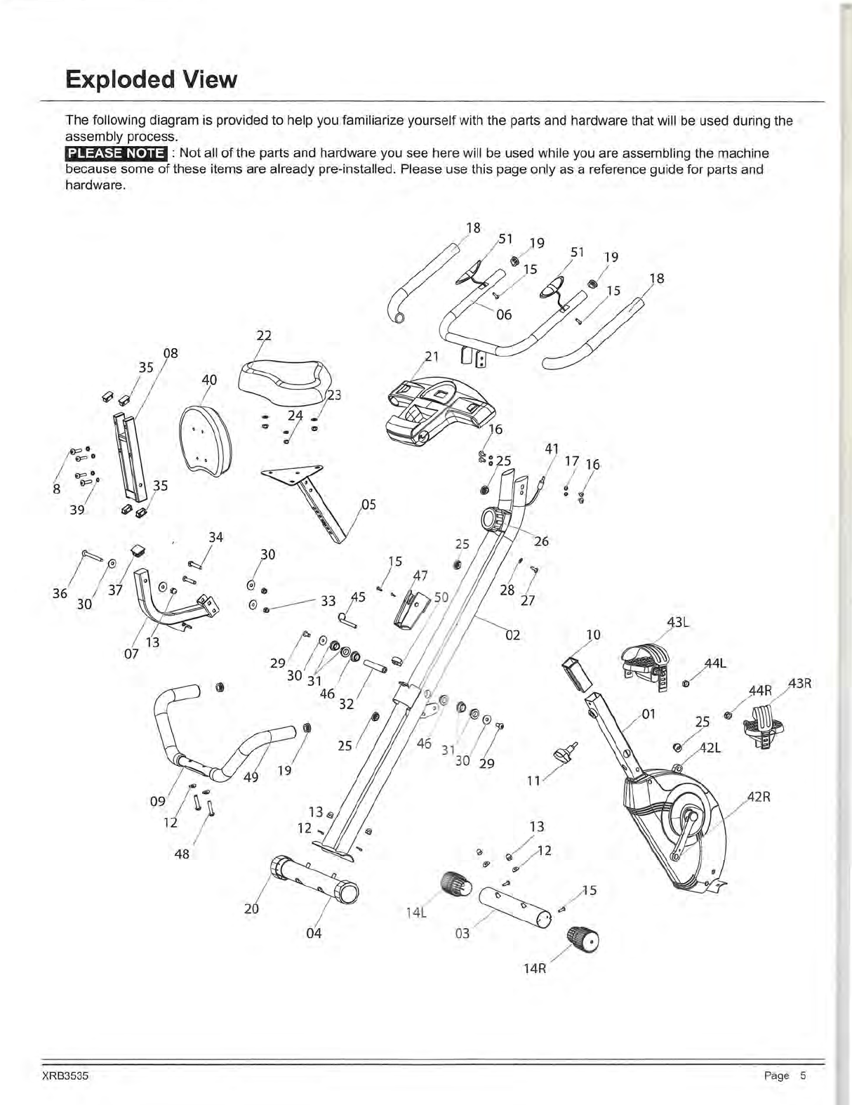
Exploded View
The following diagram is provided to help you familiarize yourself with the parts and hardware that will
be
used during the
assembly process.
PLEASE NOTE : Not all of the parts and hardware you see here will be used while you are assembling the machine
because some of these items are already pre-installed. Please use this page only as a reference guide for parts and
hardware.
18
18
8
40
]____,,_
I
~
3
CJ
=Jf
4
35
(J
I
17 16
(/
'{j
' 34
/;
®~
J
36
1
37
~©
~
30
••
13
07
20
14L
04
XRB3535 Page 5

Hardware and Tool List
The following hardware
is
used to assemble your unit. Please take a moment to familiarize yourself with these items.
~!:f!\.i:W~t•)i#I
:
Most of these parts are already pre-assembled
on
your unit.
Do
not
be
alarmed if you see parts on this
page that are not included
in
your hardware packet.
Bolt
#48 Bolt (M8x40 mm)
[2
pieces]
Pre-assembled
Washer
@
#17 Spring Washer (M6)
[4
pieces]
Pre-assembled
Nut
#44L Left Nylon Nut
(with BLACK inner nylon ring)
[1
piece]
Pre-assembled
Others
Tools (Included)
XRB3535
#38 Bolt (M8x45 mm)
[4
pieces]
Pre-assembled
#39 Spring Washer
(MS)
[4
pieces]
Pre-assembled
#44R Right Nylon Nut
(with WHITE inner nylon ring)
[1
piece]
Pre-assembled
#11
Knob Bolt
[1
piece]
S5xSOxSO
[1
piece]
#34 Carriage Bolt (M8x50mm)
[2
pieces]
Pre-assembled
#16 Bolt (M6x10 mm)
[4
pieces]
Pre-assembled
#23 Washer
(MS)
[3
pieces]
Pre-assembled
#13 Cap Nut
(MS)
[4
pieces]
Pre-assembled
#12 Arc Washer
(MS)
[4 pieces]
Pre-assembled
#24 Nylon Nut
[3
pieces]
Pre-assembled
#45 Lock-pin
[1
piece]
#30 Washer (MS)
[2
pieces]
Pre-assembled
#33 Nylon Nut (MS)
[2
pieces]
Pre-assembled
S13
-1
5-19
[1
piece]
Page 6
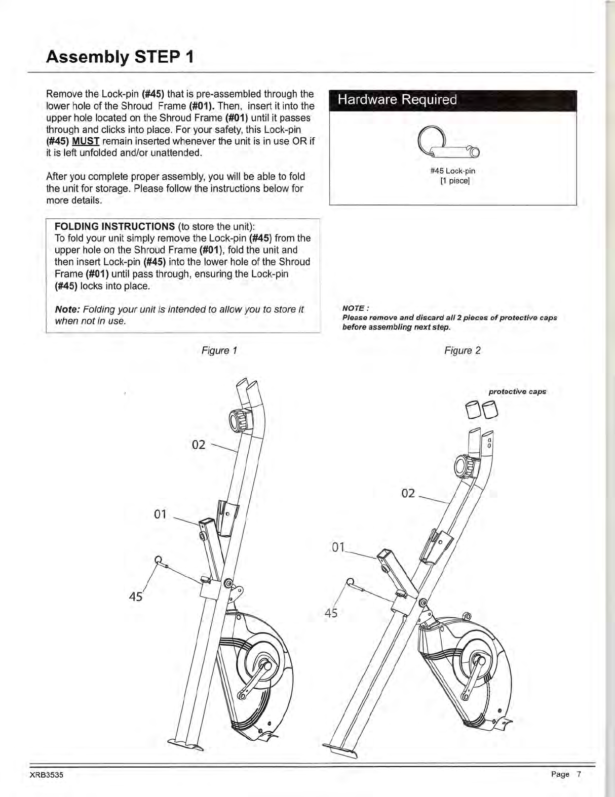
Assembly STEP 1
Remove the Lock-pin (#45) that
is
pre-assembled through the
lower hole of the Shroud Frame (#01). Then, insert it into the
upper hole located
on
the Shroud Frame (#01) until it passes
through and clicks into place. For your safety, this Lock-pin
(#45) MUST remain inserted whenever the unit
is
in
use OR if
it
is
left unfolded and/or unattended.
After you complete proper assembly, you will be able to fold
the unit for storage. Please follow the instructions below for
more details.
FOLDING INSTRUCTIONS (to store the unit):
To
fold your unit simply remove the Lock-pin (#45) from the
upper hole
on
the Shroud Frame (#01), fold the unit and
then insert Lock-pin (#45) into the lower hole
of
the Shroud
Frame (#01) until pass through, ensuring the Lock-pin
(#45) locks into place.
Note: Folding
your
unit is intended to allowyou to store it
when not in use.
Figure 1
45
XRB3535
Hardware Required
NOTE:
#45 Lock-pin
(1
piece]
Please
remove
and
discard
all
2
pieces
of
protective
caps
before
assembling
next
step.
Figure 2
protective
caps
00
Page 7

Assembly STEP 3
Remove the Washers (#23) and Nylon Nuts (#24) that are
pre-assembled
on
the Seat Cushion (#22), and set them aside
for now.
Attach the Seat Cushion (#22) to the Seat Cushion Tube (#05)
using a total of three Washers (#23) and three Nylon Nuts (#24)
that were previously removed and set aside.
Slide the Seat Cushion Tube (#05) into the Shroud Frame (#01)
with the holes
on
the Seat Cushion Tube (#05) facing downward
to
allow for alignment with the hole
on
the Shroud Frame (#01).
Next, screw the Knob Bolt (#11) through the hole
on
the Shroud
Frame (#01) and through the hole
on
the Seat Cushion Tube
(#05) that best accommodates your height and body, and screw
snugly.
22
-
t:3
05
23
WARNING!
Do not remove the Seat Cushion
(#22) for any reason after you
have installed it.
Exercising on this unit without the
Seat Cushion (#22) can result
in
SERIOUS INJURY.
Ensure the seat
is
locked
in
place
by tightening the knob prior to
use.
XRB3535
24
--
--""
151
01
,,
_ef
Hardware Required
#23 Washer (MB)
[3
pieces] #24 Nylon Nut
[3
pieces]
#11
Knob Bolt
[1
piece)
Page 9
I
J
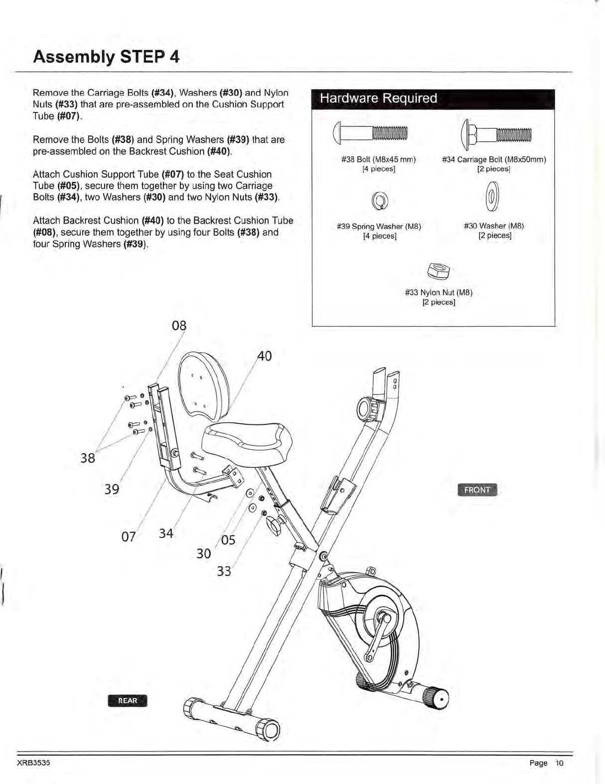
Assembly STEP 4
Remove the Carriage Bolts (#34), Washers (#30) and Nylon
Nuts (#33) that are pre-assembled
on
the Cushion Support
Tube (#07).
Remove the Bolts (#38) and Spring Washers (#39) that are
pre-assembled
on
the Backrest Cushion (#40).
Attach Cushion Support Tube (#07) to the Seat Cushion
Tube (#05), secure them together by using two Carriage
Bolts (#34), two Washers (#30) and two Nylon Nuts (#33).
Attach Backrest Cushion (#40) to the Backrest Cushion Tube
(#08), secure them together by using four Bolts (#38) and
four Spring Washers (#39).
08
XRB3535
Hardware Required
a-
#3B
Bolt
(MB
x45 mm)
[4
pieces]
#39 Spring Washer (MB)
[4
pieces]
#34 Carriage Bolt
(MB
x50mm)
[2
pieces]
#30 Washer (
MB)
[2
pieces]
#33 Nylon Nut (MB)
[2
pieces]
1g.m1
Page 10
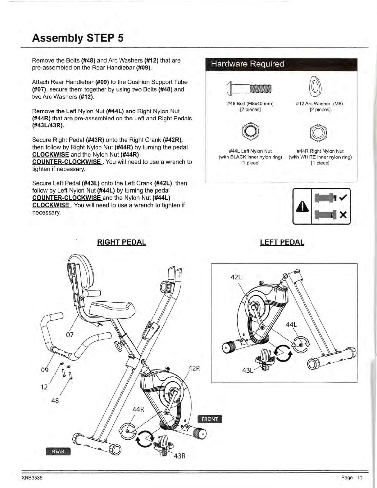
Assembly STEP 5
Remove the Bolts (#48) and Arc Washers (#12) that are
pre-assembled on the Rear Handlebar (#09).
Attach Rear Handlebar (#09) to the Cushion Support Tube
(#07), secure them together by using two Bolts (#48) and
two Arc Washers (#12).
Remove the Left Nylon Nut (#44L) and Right Nylon Nut
(#44R) that are pre-assembled on the Left and Right Pedals
(#43L/43R).
Secure Right Pedal (#43R) onto the Right Crank (#42R),
then follow by Right Nylon Nut (#44R) by turning the pedal
CLOCKWISE and the Nylon Nut (#44R)
COUNTER-CLOCKWISE .
You
will need to use a wrench to
tighten if necessary.
Secure Left Pedal (#43L) onto the Left Crank (#42L), then
follow by Left Nylon Nut (#44L) by turning the pedal
COUNTER-CLOCKWISE and the Nylon Nut (#44L)
CLOCKWISE .
You
will need to use a wrench to tighten if
necessary.
RIGHT PEDAL
oji)
12 I
48
XRB3535
Hardware Required
a____,.,_._.
#48 Bolt (M8x40 mm)
[2
pieces]
#44L Left Nylon Nut
(with BLACK inner nylon ring)
[1
piece)
#12 Arc Washer (M8)
[2
pieces)
#44R Right Nylon Nut
(with WHITE inner nylon ring)
[1
piece]
A
••
•<./
•i
x
LEFT PEDAL
Page
11

~
I
I
Assembly STEP 6
Remove the Bolts (#16) and Spring Washers (#17) that are
pre-assembled
on
the Handlebar (#21).
Attach Monitor (#21) to the Main Frame (#02), secure them
together by using four Bolts (#16) and four Spring Wash-
ers (#17). Connect the Monitor Wire (#41) to the Monitor's
(#21) jack socket to finish the assembly steps.
XRB3535
21
Hardware Required
#16 Bolt (M6x
10
mm)
[4
pieces]
#17 Spring Washer (M6)
(4
pieces]
Tension A
djustment
To
increase the te
nsion(+
higher level
of
intensity), turn
the Tension Controller (#26) in a clockwise direction.
To
decrease the tension
(-lower
level
of
intensity
),
turn
the Tension Controller (#26)
in
a counter-clockwise
direction.
"1" is the lowest level
of
tension (easiest level for
workout); "8" is the highest level of tension (most difficult
level for workout).
THE
ASSEMBLY
PROCESS IS
NOW
COMPLETE.
However, for your own safety, please make
sure to read this entire Owner's Manual which
includes safety instructions and warnings, as
well as any safety/warning labels affixed to the
product before use.
For your safety , please visually and function-
ally inspect and test the unit after assembly
is
complete.
Page 12
--
-
---
-
Computer Operation
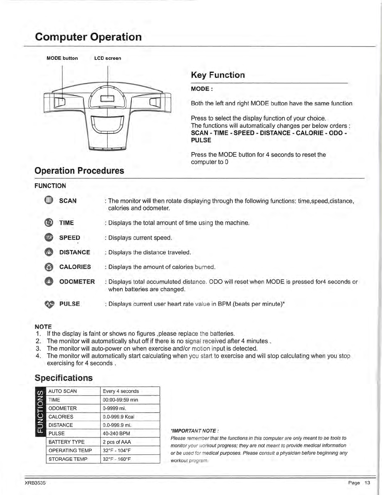
MODE button LCD screen
Key Function
MODE:
Both the left and right MODE button have the same function
Press to select the display function of your choice.
The functions will automatically changes per below orders :
SCAN -TIME -SPEED -DISTANCE -CALORIE -ODO -
PULSE
Press the MODE button for 4 seconds to reset the
computer to 0
Operation Procedures
FUNCTION
G>
SCAN
® TIME
•SPEED
e DISTANCE
(!) CALORIES
0 ODOMETER
t(/' PULSE
NOTE
: The monitor will then rotate displaying through the following functions: time,speed,distance,
calories and odometer.
: Displays the total amount of time using the machine.
: Displays current speed.
: Displays the distance traveled.
: Displays the amount of calories burned.
: Displays total accumulated distan
ce
. ODO will reset when MODE
is
pressed for4 seconds or
when batteries are changed.
: Displays current user heart rate value
in
BPM (beats per minute)*
1. If the display
is
faint or shows no figures ,please replace
th
e batteries.
2.
The monitor will automatically shut off if there
is
no
signal received after 4 minutes .
3.
The monitor will auto-power
on
when exercise and/or
mo
ti
on
input
is
detected.
4.
The monitor will automatically start calculating when you start to exercise and will stop calculating when you stop
exercising for 4 seconds .
Specifications
AUTO
SCAN
TIME
ODOMETER
CALORIES
DISTANCE
PULSE
BATTERY TYPE
OPERATING
TEMP
STORAGE
TEMP
XRB3535
Every 4 seconds
00:00-99:59 min
0-9999 mi.
0.0-999.9
Kcal
0.0-999.9 mi.
40-240 BPM
2 pcs
of
AAA
32°
F-104
°F
32°F - 160°F
*IMPORTANT
NOTE
:
Please remember that the functions in this computer are
only
meant
to be tools to
monitor
you
r work
out
progress; they are not
meant
to
provide medical information
or
be used ·or medical purposes. Please consult a physician before beginning
any
workout program.
Page 13
Computer Operation
NOTES
(Regardi
ng
the Computer Monitor
):
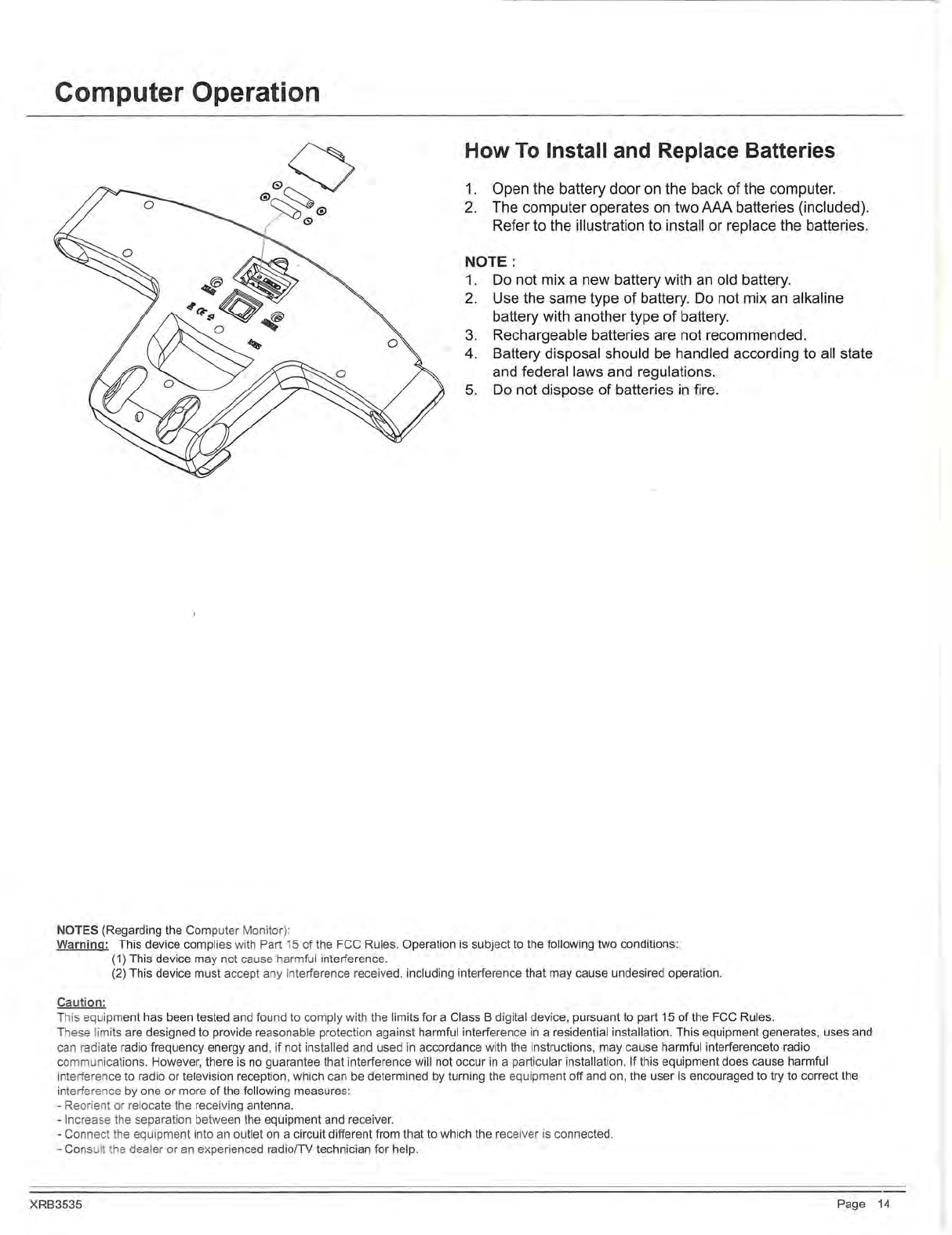
How
To
Insta
ll
and Replace Batteries
1.
Open the battery door
on
the back
of
the computer.
2. The computer operates
on
two AAA batteries (included).
Refer to the illustration to install or replace the batteries.
NOT
E:
1.
Do not mix a new battery wi
th
an
old battery.
2.
Use the same type
of
battery.
Do
not mix
an
alkaline
battery with another type
of
battery.
3.
Rechargeable batteries are not recommended.
4. Battery disposal should be handled according to all state
and federal laws and regulations.
5.
Do
not dispose of batteries
in
fire.
Warning: T
hi
s device complies with
Pa
rt
15 of t
he
F
CC
R
ul
es.
Operation
is
subject to the fo
ll
owi
ng
two condition
s:
(1) This device
ma
y not cause harm
ful
in
terference.
(2) This devi
ce
must accept any interference received, includi
ng
in
terference that may cause
un
desired opera
ti
on.
Caution:
Th
is equipment h
as
be
en tested
and
found to comply
wi
th
the limits for a Class B digital devi
ce,
pursuant to part 15 of the F
CC
Rules.
These limits are designed to provide
re
asonable protection against harmful interference
in
a residential insta
ll
atio
n.
This e
qui
pment generates, uses and
can radiate
rad
io frequency energy and, if not instal
le
d and used
in
accordance with the instruc
ti
ons, may cause harmful
in
terferenceto radio
communications. However, there is no guarantee that interference wi
ll
not occur
in
a particular
in
sta
ll
ation. If th
is
equipment does
ca
use harmful
interference
to
radio or television reception, which can
be
determined by turning the equipment off and
on
, the user is encouraged to try to correct the
interference by one or more
of
the
fo
ll
ow
in
g measures:
-
Re
orient or relocate the receiving ante
nn
a.
-Increase t
he
separation between the eq
ui
pment and
re
ce
i
ver.
-Connect t
he
equipment
in
to
an
outlet on a circuit different from that to which the receiver
is
connected.
-Co
ns
ult the dealer or
an
experienced radio/TV technici
an
for help.
XRB3535 Page 14

Safety and Maintenance
Safety & Warning
Make sure all nuts, bolts, and screws are tightened prior to use.
Be
sure that all adjustment locking devices and safety devices are properly engaged prior to use!
Never over-tighten the above-mentioned devices and parts to avoid damage to the unit.
Check for loose parts and components and make proper adjustments prior to use.
Check to see if there are any tears or bends
in
the welding or metal prior to use. Iftears or bends are found,
DO NOT use the unit and contact our CUSTOMER SUPPORT.
Extreme care must
be
taken to not allow your feet, fingers, hair, clothing, and/or any loose items to be snagged into
any portion
of
the bike when the unit
is
in
motion. Failure to follow these instructions could result
in
serious injury,
including the loss offingers.
Always wait for the pedals and other moving parts (which can gain great momentum during riding) to come to a
complete stop before dismounting the unit to avoid serious injury.
How
To
(Emergency) Stop
NOTE : Always wait for the pedals and/or any other moving parts (which can gain great momentum during riding)
to come to a complete stop before dismounting the unit to avoid serious injury.
To
reduce speed
on
the bike, you may use the combinations of your feet
on
the Left/Right Pedals (#43L/R) to gently
and safely apply counter-momentum.
Wait for the pedals
to
come to a complete stop.
Now you may safely dismount the unit
How
To Move/Transport The Bike For
NO
TE:
To
safely move, transport, and/or store the unit, please seek the
he
lp
of
capable assistants (minimum of 2 people).
The unit has integrated End Cap (#14L/R) purposely intended to h
el
p ease this process.
Position one person
on
each side at the front of the bike toward t
he
handle Bar
(one person
on
the left, and one
on
the right).
Have each person use both hands to grip the correspo
nd
ing
Fo
am
Grip for Handle Bar (#06).
(These are the safest areas to avoid injury during this p
ro
cess.)
Have both people simultaneously lift the rear end of the
un
it, leaving the weight and pressu
re
into the front of the unit
and onto the End Cap (#14L/R) to move/transport the
un
it
to
th
e desired area.
Maintenance & Care
XRB3535
Please review all safety instructions and warnings
in
th
is
entire Owner's Manual, as well as any safety/warning labels
affixed to the product before use.
Do
not use solvent cleaners. If you are
in
any doubt, do not
us
e your cleansing produc
t;
contact
CUSTOMER SUPPORT.
The specific parts
on
your unit which may see possible s
ig
ns of wear after prolonged use are listed
as
follows
(please check these parts before each use):
Tension Controller (#26); Pedals (#43L/
R);
Handleba
rs
(#06).
For any replacement warning label
s,
please contact
ou
r CUSTOMER SUPPORT at
1 (888) 266-6789
or
1 (909) 598-9876, or mail
in
a writte request to:
Hupa International Inc.
21717 Ferrero Parkway
Walnut, CA 91789
More detailed information about how to reach our
CU
S
TO
ER
SUPPORT may be found
on
Page 2 of the
Owner's Manual under the "CUSTOMER SUPPOR
T"
se
c io
n.
Page
15

Troubleshooting
(AFTER COMPLETE ASSEMBLY)
TROUBLESHOOT AREA SOLUTION
Hand Pulse Signal If the computer
is
not picking up your hand pulse signal (or you are
getting inaccurate readings), please adjust the following:
1.
Slightly moisten/dampen the palms with water
so
the sensors can detect a pulse
signal.
.,
I 2.
Do
not grip the sensors too tightly. Only moderate pressure need
be
applied.
3.
Gripping the sensors too tightly restricts and seizes detection of your pulse.
4.
Remove any rings orjewelry to prevent interference.
5. Check to ensure all pulse sensor wires are properly connected and are not dam-
aged.
6.
You
may need to refer to installation/assembly directions for the pulse sensor
wires
in
this manual.
Calories/Distance/ Ifthe computer
is
not displaying the CALORIES/DISTANCE/TIME/(ETC.)
Time (Etc.) functions (or you are getting inaccurate readings), please adjust the following:
1.
Check to ensure all computer sensor wires are properly
connected and are not damaged.
2.
You
may need to refer to installation/assembly directions for the sensor wires
in
this manual.
Computer Display Ifthe computer display is blank & not displaying any data (or does not appear to
power on), please adjust the following:
1.
Check to ensure all sensor wires are all properly connected and are not dam-
aged.
2.
Check to ensure the AC Adapter* or Batteries* are properly plugged
in
or fully
charged.
3. Check your product manual to determine if your model uses eitherAC Adapter or
batteries to power your unit.
XRB3535 Page
16

Warm-Up Instructions
Before use, you must read and understand all instructions & warnings stated
in
this Owner's Manual as well as posted
on the equipment. Before beginning any exercise program including the following flexibility exercises, please consult with
your physician.
The following flexibility exercises are provided to you as a means to prevent injury while you are exercising. A proper
warm-up routine decreases the chance of injuring your muscles while you are exercising. Please take the time to do these
flexibility exercises before and after each time you exercise.
Groin Stretch
1.
Sit with your knees flexed and
soles of feet together.
2.
Hold your ankles and bend
at your hips (keep your back
straight) as you press your
knees toward the floor with your
elbows.
Groin Stretch
1. Lie on your back and raise
your right leg as you clasp both
hands under the back of the
knee. Keep your left leg straight.
2.
Gently pull your right leg toward
your trunk without
XRB3535
raising your upper body. Switch
leg positions and repeat.
Hamstring Stretch
1. Sit with your le
ft
l
eg
extended
and bend your right l
eg
at the
knee as you place
th
e sole of
your right foot agai
ns
t the inner
thigh
of
your extend
ed
leg.
2. Flex the foot of your extended
leg (toes pointed oward
ceiling) and gently b
en
d forward
from your hips;
ke
ep your back
straight.
3. Reach your
ha
n s on your
extended leg as ar
as
possible
and then switch legs a
nd
repeat.
Trunk
Fl
exion, Prone
Trunk Twister
1. Sit with your leg extended and
bend your right knee as you
cross your right leg over your
left leg. Your right foot
of
your
extended leg foot should
be
flat
on the floor alongside your left
knee.
2. Place your left arm on the
outside
of
your right leg and
pu
ll
against that leg while twisting
your trunk as far as possible to
the right. Place your right hand
on the floor behind your but-
tocks. Reverse leg positions and
repeat.
1.
Assume the depi ed position
on
your hands and knees. Stretch your
hands out
in
fro f you and then slowly start to pull them back
in
toward
your body as you ck your chin and arch your back upward.
2.
Return to the sta ·ng position slowly.
Page 17

Warm-Up Instructions
Shoulder Stretch
1. Bring your right hand over your
right shoulder to the
upper back and bring your left
hand under your left shoulder to
the upper back.
2.
Try to reach your fingertips. If
you are not able to reach your
fingertips, use a towel
as
an
extension of your hands and
gently pull one hand toward the
other.
Reverse arm positions and
Quadriceps Stretch
1.
Stand
on
your left leg and hold
onto a support with your left
hand.
2.
Flex your right leg behind you,
grasp your ankle or foot with
your right hand and pull your
foot toward your buttocks. Keep
your back straight and right
knee pointed down.
Repeat
on
the other leg.
Calf Twister
1. Place both hands against a wall
to aid your balance. Press the
ball of your left foot against the
wall and keep the heel
of
the
same foot rested
on
the floor
(make sure your left knee
is
bent).
2.
Slowly start to straighten your
left knee and you will feel the
muscles
in
your left calf stretch.
Switch
leg
positions and repeat.
Page 18

THANK YOU FOR YOUR PURCHASE
MODEL NO.: XRB3535
Please fill
in
the information below and keep this manual
along with your sales receipt as proof
of
purchase.
Serial Number :
Date
of
Purchase :
Retailer:
Hupa International Inc.
21717 Ferrero Parkway
Walnut, CA 91789
Phone: 1 (888) 266-6789
Fax : 1 (909) 598-6707
Email : [email protected]
Ver. 09/07/2017 Printed in China
Table of contents
Other Body Rider Exercise Bike manuals


