Boehringer Miditron Junior II User manual

Service Manual Miditron®
Junior
II / ID 1997491 / MJ / 1.0 - June 1998 / Page 1
Miditron®
Junior
II
Service Manual

Service Manual Miditron®
Junior
II / ID 1997491 / MJ / 1.0 - June 1998 / Page 2
Table of contents
Short operating instructions .......................................................................6
1. General Note .................................................................................................7
1.1 Limitations .............................................................................................................7
1.2 Mailing / telephone address ................................................................................7
1.3 Security advice ......................................................................................................8
1.4 Confirmation declaration ....................................................................................10
2. Documentation ...........................................................................................11
2.1 Update service for this manual ..........................................................................11
2.2 Instrument code for service ...............................................................................11
3. Introduction.................................................................................................12
3.1 System description .............................................................................................12
3.1.1 Function Elements ............................................................................................ 13
3.1.2 Measuring Principle .......................................................................................... 15
3.1.3 ConcentrationTable (Program I) ...................................................................... 17
3.1.4 Changing Range Remisson Bordes ................................................................ 18
3.2 System Specification ..........................................................................................19
3.3 Service Concept ..................................................................................................20
3.3.1 Service level ...................................................................................................... 20
3.3.2 Handling of warranty and repairs .................................................................... 20
4. Installation ..................................................................................................25
4.1 Checking for Damage inTransit .........................................................................25
4.2 Unpacking ............................................................................................................25
4.3 Proper Setting......................................................................................................25
4.4 Setting Up.............................................................................................................25
4.5 Inserting Printer Paper........................................................................................27
5. Calibration...................................................................................................28
6. Operation ....................................................................................................31
6.1 Overview ..............................................................................................................31
6.2 Normal Mode........................................................................................................32
6.3 Accelerated Mode................................................................................................32
6.4 Fast Mode.............................................................................................................32
6.5 Principle movement of the Miditron® Junior II.................................................33
7. Service mode and adjustment ..................................................................34
7.1 How to make adjustments ..................................................................................34

Service Manual Miditron®
Junior
II / ID 1997491 / MJ / 1.0 - June 1998 / Page 3
Table of contents
7.2 General .................................................................................................................35
7.3 Procedure.............................................................................................................35
8. Adjustment / Dismantling ..........................................................................40
9. Mechanics ...................................................................................................41
9.1 Mechanical moduls .............................................................................................41
9.1.1 Transport arm .................................................................................................... 41
9.1.2 Tray..................................................................................................................... 41
9.1.3 Top of housing .................................................................................................. 42
9.1.4 PCB Main ........................................................................................................... 43
9.1.5 PCB Interface .................................................................................................... 44
9.1.6 Display ............................................................................................................... 45
9.1.7 Printer ................................................................................................................ 46
9.1.8 Status LED......................................................................................................... 47
9.1.9 Keyboard............................................................................................................ 48
9.1.10 PCB Measuring Head........................................................................................ 49
9.1.11 LED Measuring Head Home Position............................................................... 50
9.1.12 LED Home Position ........................................................................................... 51
9.1.13 Motor Belt Drive CrossTransport .................................................................... 52
9.1.14 Motor Measuring Head Unit.............................................................................. 53
9.1.15 Tooth Bar Measuring Head Unit ....................................................................... 54
9.1.16 Carrier for tray ................................................................................................... 55
9.1.17 Reference Field Carrier..................................................................................... 56
9.1.18 Crossbar complete............................................................................................ 57
9.1.19 CrossTransport ................................................................................................. 58
10. Electronics ................................................................................................59
10.1 Overview Electronics ..........................................................................................59
10.2 Power supply .......................................................................................................60
10.3 Electronic modules .............................................................................................62
10.3.1 PCB Main ........................................................................................................... 62
10.3.2 PCB Interface .................................................................................................... 65
10.3.3 Display ............................................................................................................... 67
10.3.4 Printer ................................................................................................................ 67
10.3.5 Status LED......................................................................................................... 67
10.3.6 Keyboard............................................................................................................ 68
10.3.7 PCB Measuring Head........................................................................................ 68
10.3.8 LED Measuring Head Home Position............................................................... 69
10.3.9 LED Home Position ........................................................................................... 69

Service Manual Miditron®
Junior
II / ID 1997491 / MJ / 1.0 - June 1998 / Page 4
Table of contents
10.3.10 LED reference position..................................................................................... 70
10.3.11 Motor Belt Drive CrossTransport .................................................................... 70
10.3.12 Motor Measuring Head Drive............................................................................ 71
10.4 Circuit diagram ....................................................................................................72
10.4.1 PCB Main ........................................................................................................... 72
10.4.2 PCB Interface .................................................................................................... 77
10.4.3 PCB Measuring Head........................................................................................ 81
11. Software ....................................................................................................82
11.1 Overview ..............................................................................................................82
11.2 Flow Diagram of Menu Selection .......................................................................83
11.2.1 Flow Diagram of theWorklist Menu ................................................................. 84
11.2.2 Flow Diagram of theWorking Mode Menu....................................................... 85
11.2.3 Flow Diagram of the Reprint Menu .................................................................. 86
11.2.4 Flow Diagram of the Setup Menu..................................................................... 87
11.2.4.1 Flow Diagram of Color Setup ........................................................................... 89
11.2.4.2 Flow Diagram of Clarity Setup ......................................................................... 90
11.2.4.3 Flow Diagram of Parameter Setup ................................................................... 91
11.3 Service/Status Software .....................................................................................92
11.4 Software update ..................................................................................................92
11.4.1 Software update via chip cards........................................................................ 92
11.4.2 Software update via printer interface .............................................................. 93
11.5 Loading instrument settings via Download......................................................97
11.5.1 Specification of the INI-file ............................................................................... 98
11.6 Saving instrument settings via Upload ...........................................................100
12. Interface ..................................................................................................101
12.1 Host Interface.....................................................................................................101
12.2 Character definitions, representation conventions .......................................102
12.3 Protocols ............................................................................................................103
12.4 Upload timing and handshake .........................................................................106
12.5 Download timing and handshake ....................................................................108
12.6 Protocol structure .............................................................................................110
12.6.1 Protocol "/REP/": Repeat request .................................................................. 110
12.6.2 Protocol "/SPM/": Start Communication ....................................................... 110
12.6.3 Protocol "/MOR/":Receipt confirmed/Request for next set ......................... 110
12.6.4 Protocol "/END/": End of communication ..................................................... 110
12.6.5 Protocol "/SPE-D/ + Data": Data protocol color + turbidity ......................... 111

Service Manual Miditron®
Junior
II / ID 1997491 / MJ / 1.0 - June 1998 / Page 5
Table of contents
12.6.6 Protocol "/SPE-E/ + Data": Data protocol results ....................................... 111
12.6.7 Protocol "/SPE-A/ + Pat-Id.": Data protocol Pat-Id. ...................................... 112
12.7 Format of results-data : ....................................................................................112
12.7.1 Structure of results-data Programm-1 (International) :................................ 112
12.8 Procedures for checking test bytes .................................................................114
12.8.1 European language variations of Miditron® software: LRC test bytes ....... 114
12.8.2 American/Canadian language version of Miditron® Junior II software: ..... 115
12.8.3 Automatic adaption to the test procedure used by the host ....................... 116
13. Troubleshooting ...................................................................................... 117
13.1 Error at self-test.................................................................................................117
13.2 Repairable errors during normal mode ...........................................................118
13.3 Non-repairable errors during normal mode (Major Error) .............................119
13.4 Errors during INI-file Download .......................................................................120
13.5 List of all error codes........................................................................................121
14. Spare Parts .............................................................................................127
14.1 Complete spare part list ...................................................................................127
14.2 Part identification ..............................................................................................128
14.3 Exploded view Miditron® Junior II...................................................................131
15. Instrument, Strips, Accessories............................................................133
15.1 Complete list......................................................................................................133
16. Interface Assignment.............................................................................134
16.1 Host/PC interface...............................................................................................134
16.2 External Printer interface..................................................................................135
16.3 Barcode reader interface ..................................................................................135
17. Routine Care and Cleaning ...................................................................136
17.1 General ...............................................................................................................136
17.2 Cleaning .............................................................................................................136

Service Manual Miditron®
Junior
II / ID 1997491 / MJ / 1.0 - June 1998 / Page 6
Short operating instructions
Directions in Brief
Please read carefully the sections marked with this symbol in the margin!
Miditron®
Junior
II is designed for ease of use.To carry out routine strip measurements in Normal Mode
(sequential reading with automatic consecutive numbering), proceed as follows:
Switch on Miditron®
Junior
II.You see displayed:
Please empty the waste tray.
Once the waste tray is empty and the self-check has finished, the analyzer is
ready.You see displayed.
1. Press <Start> and follow the display messages:
2. When the status LED flashes green and the beep tone sounds ("Dip Strip 1" is displayed), briefly dip
the test strip in the urine sample (for about 1 second) and then remove it again, drawing the edge of
the strip over the rim of the specimen container to wipe off excess urine.
3. While the status LED is green, you may insert the test strip, reagent zones upwards, into the insertion
area between the two guides on the leading edge of the strip receiving tray.
The end of the test strip must be supported by the rear inside edge of the strip receiving tray
(Fig.10).
WARNING:To prevent injury, keep hands away from the analyzer when it is transporting
test strips!
4. After about 20 seconds the first test strip will be transported from the waiting position to the
measuring position and "PleaseWait" will be displayed.When the display shows "Dip Strip 2", repeat
the procedure for the second and any subsequent test strips.
5. The first test strip will be measured 60 seconds after it was dipped and the result will be automatically
printed as long as the internal printer was not disabled in the SETUP menu.When a strip is no longer
detected at the measuring position, Miditron®
Junior
II automatically returns to the initial state
("READY - <START>" is displayed).
IMPORTANT:
Before operating Miditron®
Junior
II for the first time, you have the option of entering various
settings in the SETUP menu.
For your own safety, and to avoid operator errors, please read the following operating
instructions carefully.
Please refer to the relevant sections of the Operator’s Manual for information on selection of SET-
UP menu options, calibration, working with Patient ID’s,cleaning and maintenance.
"Please empty the waste tray"
Empty Waste Tray
"The analyzer is ready to
measure"
READY - <START>

Service Manual Miditron®
Junior
II / ID 1997491 / MJ / 1.0 - June 1998 / Page 7
1.1 Limitations
The data and information provided in this manual
correspond to the state of knowledge existing at the time of
introducing the Miditron®
Junior II
on the market.Any
important changes will be taken into account in the next
edition of this manual.
The packaging leaflet should be regarded as authoritative.
This service manual was created for the telephone service
and technical service staff.
The operation manual contains special information for the
telephone service.
1.2 Mailing / telephone address
Service department, DA-ST
Telephone: +49 (0) 621 / 759 / 4116
Fax: +49 (0) 621 / 759 / 3985
Hot-line logistic (RA)
Telephone: +49 (0) 621 / 759 / 8094
Fax: +49 (0) 621 / 759 / 8093
When calling from outside Germany, add the international
dialing code at the beginning and omit the first‘0’.
1. General Note

Service Manual Miditron®
Junior
II / ID 1997491 / MJ / 1.0 - June 1998 / Page 8
1. General Note
1.3 Security advice
Please carefully read the paragraphs marked by a
warning triangle!
This instrument was constructed in accordance with
DINVDE 0750, Part 1/DIN IEC 601, Part 1,“Medical
Electrical Equipment; Part 1: General Requirements for
Safety”and checked to meet all technical demands on
safety before leaving the factory.
The instrument received the „GS“ (Geprüfte Sicherheit =
safety-tested) label for meeting the safety requirements of
theVDE (Verein Deutscher Elektronik-Hersteller = Society
of German Electronics Manufacturers) and meets the
requirements of the MedGV (Medizinische Geräte-
verordnung = Medical Instrument Regulation).
To maintain these conditions and guarantee safe operation,
the operator should read this information and observe the
warnings given in these operating instructions.
The instrument should be used only with the external power
supply included in the delivery.
This instrument belongs to Protection Class I (protective
conductor).
Do not insert the plug into any type of AC outlet other than a
shock-proof outlet.Do not use an extension cord without a
protective conductor to prevent that the protective effect is
circumvented.
Interrupting the earth conductor inside or outside of
the instrument or disconnecting the earth conductor
lug may create a hazardous situation for the operator.
Do not open the covers or remove parts that cannot be
opened or removed by hand, as this can expose live parts.
Connectors may also be live.Any adjustment, maintenance
or repair on an opened instrument with the power on should
be carried out only by trained personnel authorized by
Boehringer Mannheim who are aware of the danger
involved.
If you suspect that the instrument can no longer be
operated safely, turn it off and take steps to ensure that it
cannot be turned on accidentally.Make certain that the
Miditron®
Junior
II is operated by trained personnel only.
To prevent injury, keep hands away from the analyzer
when it is transporting a strip.

Service Manual Miditron®
Junior
II / ID 1997491 / MJ / 1.0 - June 1998 / Page 9
1. General Note
A personal computer or printer connected to the analyzer
must meet the regulations of EN 60950, UL 1950 or CSA
C22.2 No.950.
General Information:
The data and information contained in this manual are
current as of issue.Any basic changes will be included in
subsequent editions.In case of uncertainty, the package
insert included with the product in question shall prevail.
The instrument meets the requirements of Overvoltage
Class 2 and Pollution Class 2.
Medical Instrument Regulation („MedGV“)
MedGV is a safety regulation for technical medical
instruments (effective only in Germany).
According to the MedGV of 01/14/85, the Miditron®
Junior
II
is classified in Group 3.The user must follow the proper
guidelines for Group 3.
Reference:
Regulation on Safety ofTechnical Medical Instruments.
Author:Adolf Krebs, ISBN 3-921958-41-S, 1985 Bibliomed.
Published by:MedizinischeVerlagsgesellschaft mbH,
Melsungen.
Miditron®
Junior
II should be used by qualified persons
only.

Service Manual Miditron®
Junior
II / ID 1997491 / MJ / 1.0 - June 1998 / Page 10
1. General Note
1.4 Confirmation declaration
Confirmation declaration for electromagnetic compatibility
according to the laws of the European Union.

Service Manual Miditron®
Junior
II / ID 1997491 / MJ / 1.0 - June 1998 / Page 11
2. Documentation
2.1 Update service for this manual
New information and modifications will be sent viaTechnical
News.Please send us your name and address to ensure
you receive updates automatically.
Update Service:
Fax this page toTechnical Service-Boehringer Mannheim
+49 (0)621 759 3985
Name:......................................................
Address:..................................................
..................................................................
..................................................................
FAX No. + ____ _____________________
You will find the version identification in the bottom line of
every page.
Explanation of the index:
Service Manual Miditron®
Junior
II / ID 1702602 / MJ /
Vers.1.0 - June 1998 / Page 5
Instrument: Miditron®
Junior
II
Order- number: 1702602
Instrument code: MJ
Version: 1.0
Date of edition: June 1998
Page: 5
2.2 Instrument code for service
The service code of Miditron®
Junior
II is: MJ

Service Manual Miditron®
Junior
II / ID 1997491 / MJ / 1.0 - June 1998 / Page 12
3. Introduction
3.1 System description
Urine test strips simplify laboratory diagnosis through their
ease of use, sensitivity and specificity.These benefits allow
you to identify pathological changes in the urine quickly and
reliably.
Automated urinalysis with Miditron®
Junior
II assures that
the reading of results is standardized by eliminating
potential sources of error associated with visual reading of
test strips (such as unfavourable lighting conditions at the
workplace, differences in operators’ability to discriminate
between colours and keep to prescribed times, etc.).The
test strips used are multi-parameter strips for measuring
specific gravity, pH, leukocytes, nitrite, protein, glucose,
ketone, urobilinogen, bilirubin and erythrocytes in urine.
Service Manual Miditron®
Junior
II / ID 1997491 / MJ / 1.0 - June 1998 / Page 13
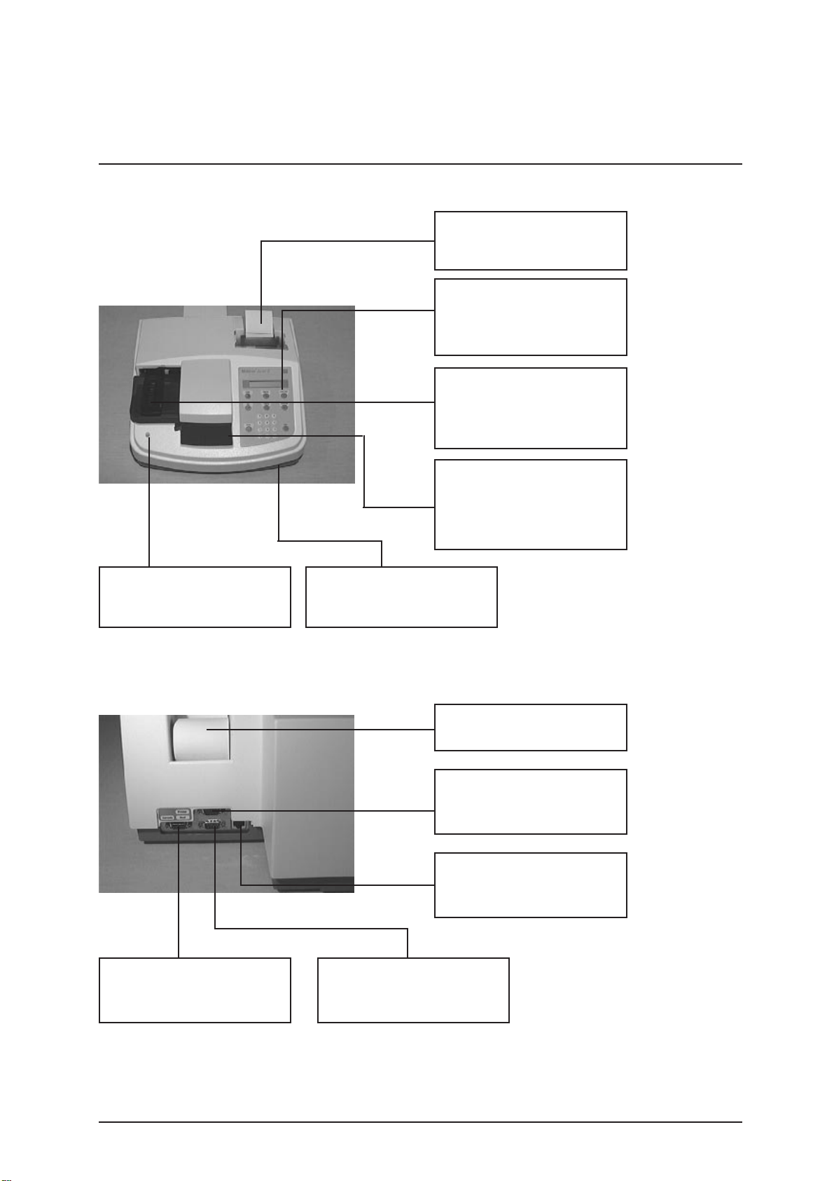
3.1.1 Function Elements
3. Introduction
Built in printer with lid
for documentation of the
results
Transport arm
Transports test strip from
wait position into measuring
position
Waste tray
Three functional areas, test
strip insertion, incubation/
measurement area and
waste container
Status LED
3 different colours indicates
the status of the instrument
DC- socket
To connect the external
power supply
Serial interface
Used to connect to external
printer
Serial interface
Used to connect to a
barcode reader
Serial interface
Used to connect to a host,
PC
Printer paper
Thermal paper
Keyboard/ Display
Contains 6 function keys, 10
num.keys and liquid crystal
display
Program chip card
Contains program for SW
update

Service Manual Miditron®
Junior
II / ID 1997491 / MJ / 1.0 - June 1998 / Page 14
3. Introduction
Color
For manually selecting
colour and clarity for
inclusion with results.
ç
Backspace key for correcting
input, scrolling backwards or
jumping back one
External power supply,
provides the instrument with
+5V DC and +12V DC
Reprint
Reprints the patient report(s)
as defined in the Reprint
menu.
Display
The display consists of 1 line
of 16 characters.
Enter
Used to terminate keyboard
input, e.g.<0-9> and to
confirm an option or a
procedure.
Set
Used to select a menu
option.
<0-9> and <.>
Used to enter (alpha)
numeric values.
Line Feed
advances paper one line at a
time or advances
continously while key is
depressed
Calibrate
Starts the calibration
procedure.
Paging
Used to scroll forwards
vertically through menus
without branching to menu
options and without saving
settings.
Start
Used to start test strip
measurement, also to
escape from menus back to
"READY - <Start>", "ACC
MODE Start" or "FAST
MODE <START>", to stop
printing during Reprint, and
to acknowledge warning
messages and prompts.
Power cord
(Country specific)
Service Manual Miditron®
Junior
II / ID 1997491 / MJ / 1.0 - June 1998 / Page 15
3. Introduction
3.1.2 Measuring Principle
Miditron®
Junior
II is a semi-automated reflectance
photometer for in-vitro semi-quantitative reading of urine
test strips from Boehringer Mannheim.The light sources
(light-emitting diodes, LED’s for short) and reading times
are optimized for the reaction chemistry and colour
development occurring on the test pads.
The measuring head of Miditron®
Junior
II contains 3 LED’s
of differing wavelengths.The test strip is held stationary at
the measuring position and the measuring head moves over
each test pad in turn, starting from a "Reference position"
used to test the optical system.
During measurement, Miditron®
Junior
II checks that the
test strip is properly positioned under the measuring head
by carrying out a plausibility check on the light that is
reflected.If the strip is not properly positioned under the
measuring head, Miditron®
Junior
II prints an error
message.
Reading is done electro-optically, as follows:
An LED (1) flashes light of a defined wavelength at an
optimum angle onto the surface of the test pad (2).The light
hitting the surface is reflected with an intensity that is
dependent on the colour of the test pad, and is received by
a photodiode detector (3) positioned directly above the test
pad.The detector sends an analogue electrical signal to the
analogue-to-digital converter (4), which converts it to a digi-
tal figure.The microprocessor (5) corrects the digital figure
based on a value from an internal reference pad and
converts it to a relative value by scaling to a calibration
standard, and then computes the absolute reflectance
value.
5
3
1
Detector Analog-to-Digital Converter Microprocessor
Test Area
LED
Concentration Result
4
2

Service Manual Miditron®
Junior
II / ID 1997491 / MJ / 1.0 - June 1998 / Page 16
The semi-quantitative concentration result is determined by
comparing the absolute reflectance value with the so-called
range boundaries ( = constant, parameter-specific
reflectance values stored in the analyzer).
Results can be printed out, saved in memory, and sent to a
computer.
The wavelengths of the LED’s used to measure each of the
urine test strip parameters are listed in the table below.The
results of certain parameters are improved through the use
of two different wavelengths.The third LED is for future
options
The photometric reflectance measurement for all of the
parameters is carried out after an incubation time of 60
seconds.As with earlier urine analyzers from Boehringer
Mannheim, allowance for intrinsic urinary colour, which is a
recognized interfering factor, is made through measurement
of a blank reagent pad, the so-called "compensation pad".
Upon immersion into the urine sample, the compensation
pad absorbs the sample liquid and assumes the intrinsic
colour of the urine.Measuring the compensation pad helps
prevent false positives when the urine sample is strongly
coloured.
In strongly alkaline urine samples, Miditron®
Junior
II
automatically corrects the result obtained when the test pad
for specific gravity is read.
Miditron®
Junior
II reads the strip and determines urine
colour by evaluating the compensation pad.The settings
necessary for this are selected in the Setup menu.Whether
the colour is to be printed together with the results is also
defined in the Setup menu.
3. Introduction
Parameter Measuring Wave length [nm]
Specific Gravity 620
pH 557 and 620
Leukocytes 557
Nitrite 557
Protein 557
Glucose 557
Ketone 557
Urobilinogen 557
Bilirubin 557
Erythrocytes 557 and 620
Color 557 and 620

Service Manual Miditron®
Junior
II / ID 1997491 / MJ / 1.0 - June 1998 / Page 17
3. Introduction
3.1.3 ConcentrationTable (Program I)
Miditron®
Junior
II prints the test results in the following
concentration ranges:
Parameter Conventional SI Arbitrary (Standard)
Specific Gravity 1.000 1.000 1.000
(SG) 1.005 1.005 1.005
1.010 1.010 1.010
1.015 1.015 1.015
1.020 1.020 1.020
1.025 1.025 1.025
1.030 1.030 1.030
pH 5 5 5
666
6.5 6.5 6.5
777
888
999
Leukocytes neg. neg. neg.
(LEU) 25 /µl 25 /µl +
100 /µl 100 /µl ++
500 /µl 500 /µl +++
Nitrite neg. neg. neg.
(NIT) pos. pos. pos.
Protein neg. neg. neg.
(PRO) 25 mg/dl 0.25 g/l +
75 mg/dl 0.75 g/l ++
150 mg/dl 1.5 g/l +++
500 mg/dl 5 g/l ++++
Glucose norm. norm. neg.
(GLU) 50 mg/dl 3 mmol/l +
100 mg/dl 6 mmol/l ++
300 mg/dl 18 mmol/l +++
1000 mg/dl 56 mmol/l ++++
Ketone neg. neg. neg.
(KET) 5 mg/dl 0.5 mmol/l +
15 mg/dl 1.5 mmol/l ++
50 mg/dl 5 mmol/l +++
150 mg/dl 15 mmol/l ++++
Urobilinogen norm. norm. neg.
(UBG) 1 mg/dl 17 µmol/l +
4 mg/dl 68 µmol/l ++
8 mg/dl 135 µmol/l +++
12 mg/dl 203 µmol/l ++++
Bilirubin neg. neg. neg.
(BIL) 1 mg/dl 17 µmol/l +
3 mg/dl 50 µmol/l ++
6 mg/dl 100 µmol/l +++
Erythrocytes neg. neg. neg.
(ERY) 10 /µl 10 /µl +
25 /µl 25 /µl ++
50 /µl 50 /µl +++
150 /µl 150 /µl ++++
250 /µl 250 /µl +++++

Service Manual Miditron®
Junior
II / ID 1997491 / MJ / 1.0 - June 1998 / Page 18
3. Introduction
3.1.4 Changing Range Remisson Bordes
The boundaries of the reflectance ranges used by
Miditron®
Junior
II to compute and output the test results
were derived from rigorous comparative tests carried out by
Boehringer Mannheim with native urine.If required, the
factory-set default ranges for Miditron®
Junior
II may be
changed to suit individual laboratories’requirements.
Results obtained based on individually modified ranges are
flagged with an asterisk * under the "Urinalysis" headline on
the patient report.
The ranges for the parameters pH and SG cannot be
modified;nor can the thresholds for wavelength changes for
pH and ERY.
Operator´s Manual outlines how ranges can be selected.
Boehringer Mannheim can give no guarantee as
to the accuracy of results when range
boundaries have been changed.

Service Manual Miditron®
Junior
II / ID 1997491 / MJ / 1.0 - June 1998 / Page 19
3. Introduction
3.2 System Specification
Dimensions: Height: 195 mm
Width: 349 mm
Depth: 470 mm
Weight: 7.45 kg
Interfaces: 3 serial RS 232 C interfaces
(host/PC, barcode reader, external printer)
PowerSupply: External Universal Power Supply Model No.78-095-0300
with integral ON/OFF switch
Input: 110V - 240V;50-60 Hz;0.4-0.2 A
Output: 5 V 2.0 A
12V 2.0 A
Power Consumption: Operation: 30 W
Standby: 15W
System Description: Type: reflectance photometer
Light source: LED’s (light emitting diodes)
Wavelengths: 557 nm, 620 nm
(the 656 nm LED is for future options)
Measuring head: 1 measuring head with 3 LED’s
Work flow: approx.36 seconds (Normal Mode)
approx.20 seconds (Accelerated Mode)
approx. 12 seconds (Fast Mode)
Incubationtime: 60 seconds
Printer: Seiko thermal line printer
Display: liquidcrystal display,1line,16characters
Environmentalconditions: Operating Non-Operating
Temperature: +15°C - +34°C -20°C - +60°C
Relativehumidity: 20 % 80 % 20 % 95 %
Optimum Opt.Temperature: +22°C - +26°C
operatingconditions: Opt. Rel. Humidity: 30 % 60 %

Service Manual Miditron®
Junior
II / ID 1997491 / MJ / 1.0 - June 1998 / Page 20
3. Introduction
3.3 Service Concept
3.3.1 Service level
From the early stage of development,Miditron®
Junior
II
was designed for simple error detection and easy
exchangeability of modules.This gives the service
workshops the possibility of a fast and easy repair of the
instrument on service level A (module level).No big stock or
expensive equipment is necessary and service technicians
are easier to train.Also, a permanent technical
improvement in layout and economic production.
SMD-technology increases reliability on better economical
basis in production. Repair costs often do not relate to
production costs for new parts with the latest improvement.
This cuts the number of repairable parts.
On repairable modules the quality and function is always
provided by the manufacturer according to the latest
technology.This keeps Miditron®
Junior
II always on the
highest quality level.
The exchange price for modules will be kept on a low level
to guarantee repairs, on economical basis.
3.3.2 Handling of warranty and repairs
Warranty period for instruments and spare parts
The warranty period for instruments is 16 months
starting with the date of shipment ex works Mannheim/
Federal Republic of Germany or 12 months starting with
the date of the first installation, whichever period is
shorter.
The warranty period for spare parts is 6 months from
installation date of the part, however not longer than 24
months after having delivered ex works Mannheim/
Federal Republic of Germany.
Hint:
In case the instrument has a remaining warranty period
of more than 6 months, the parts remain under warranty
until the warranty period of the instrument expires.
Table of contents
Other Boehringer Laboratory Equipment manuals

Popular Laboratory Equipment manuals by other brands


Quantum
Quantum Q9000VOIP Series Programming manual

EYELA
EYELA SB-1300 instruction manual

Hanna Instruments
Hanna Instruments HI 931001 instruction manual

ADInstruments
ADInstruments PowerLab owner's manual

Integra
Integra Fireboy Plus 144000 operating instructions

Nippon Genetics Europe
Nippon Genetics Europe FastGene FAS-DIGI PRO manual