Atlas SunSpray User manual
Operating Manual
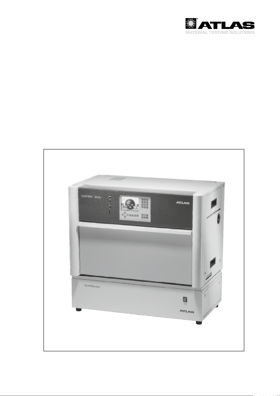
SUNSPRAY
®
SunSpray
for SUNTEST XLS+

Operating Manual SunSpray for SUNTEST®XLS+
- 2 -
Copyright
This operating manual is protected by copyright. The rights incorporated for reprinting, photomechanical or digital
further processing or any other form of reproduction, even in part, are allowed only with the written permission of
Atlas Material Testing Technology GmbH. This does not apply to reproduction for company internal purposes. The
contents of the operating manual are subject to change at any time without notice. The German version of this oper-
ating manual is binding for translations into foreign languages.
Atlas Material Testing Technology GmbH • 63589 Linsengericht • Germany
Trademarks
SUNTEST®XLS+ is a registered trademark of Atlas Material Testing Technology GmbH.
All other trademarks used in this operating manual are the exclusive property of the manufacturers concerned.

- 3 -
Operating Manual SunSpray for SUNTEST®XLS+
Contents Page
1 Instructions for safe operation ..................................................................................................................... 5
1.1 Explanation of the symbols ......................................................................................................................... 7
1.2 General safety instructions .......................................................................................................................... 8
2 Delivery ......................................................................................................................................................... 10
2.1 Packaging ................................................................................................................................................. 10
2.2 Scope of delivery ....................................................................................................................................... 10
3 Requirements for installation ...................................................................................................................... 11
3.1 Room climate ............................................................................................................................................ 11
3.2 Room ventilation ....................................................................................................................................... 11
3.3 Dimensions / Set up .................................................................................................................................. 11
3.4 Water supply ............................................................................................................................................. 12
3.5 Transport ................................................................................................................................................... 12
3.6 Installation and space requirements ......................................................................................................... 13
4 Product Description ..................................................................................................................................... 14
4.1 View from the front and right ..................................................................................................................... 14
5 Functional description ................................................................................................................................. 15
5.1 Equipment function ................................................................................................................................... 15
5.2 Safety devices ........................................................................................................................................... 15
6 Start up .......................................................................................................................................................... 16
6.1 Starting the device for the rst time ........................................................................................................... 16
6.2 Checking the device components ............................................................................................................. 16
6.3 Filling the water tank ................................................................................................................................. 17
6.4 Emptying the water tank ............................................................................................................................ 18
6.5 Mounting the protective plate .................................................................................................................... 18
6.6 Inserting the sample table ......................................................................................................................... 18
6.7 Inserting the water deector plate ............................................................................................................. 18
6.8 Incoming power connection ...................................................................................................................... 19
7 Operation ...................................................................................................................................................... 20
7.1 Menu structure of the device control ......................................................................................................... 20
7.2 Setting options .......................................................................................................................................... 21
8. Shut down ..................................................................................................................................................... 21
8.1 Turning off the device ................................................................................................................................ 21
8.2 Turning off the device in an emergency .................................................................................................... 21
9. Troubleshooting ........................................................................................................................................... 22
9.1 Error messages and troubleshooting ........................................................................................................ 22
10. Maintenance .................................................................................................................................................. 23
10.1 Inspection .................................................................................................................................................. 23
10.2 Repair ........................................................................................................................................................ 23
10.3 Cleaning .................................................................................................................................................... 24
11. Technical data ............................................................................................................................................... 25
12. Notes ............................................................................................................................................................. 26
13. Declaration of conformity ............................................................................................................................ 27

Operating Manual SunSpray for SUNTEST®XLS+
- 4 -
Fig. 1 Installation and space requirements .................................................................................................... 13
Fig. 4.1 View from the front and right ................................................................................................................ 14
Fig. 5.1 Equipment function ............................................................................................................................... 15
Fig. 6.0 Filling the water tank ............................................................................................................................. 17
Fig. 6.1 Inserting the sample table ..................................................................................................................... 18
............................................................................................. 18
Fig. 6.3 Incoming power connection ................................................................................................................. 19
Fig. 7.1 Menu structure ....................................................................................................................................... 20
Fig. 8.1 Turning off the device ............................................................................................................................ 21

- 5 -
Operating Manual SunSpray for SUNTEST®XLS+
Instructions for the user:
This operating manual describes the SunSpray accessory (spraying unit) for the SUNTEST®XLS+ weathering instru-
ment.
The following persons can be considered properly qualied:
• Persons who have gained their knowledge in special training courses
• Persons who have been trained for the operation and operating possibilities of the SUNTEST XLS+ instrument
and the accessory based on this operating manual
• Persons who are able to assess the activity that they perform based on work experience and instruction in the
relevant safety conditions and recognize possible hazards
Service:
• Work on the electrical components may only be carried out by qualied personnel
Cleaning:
• Cleaning work on the accessories may only be carried out by trained personnel with instruction based on this
operating manual
to use the existing scope of functions and to avoid possible damage to the accessory.
If special problems occur which are not explained in enough detail in this operating manual, please contact
your supplier for your own safety.
1Instructions for safe operation

Operating Manual SunSpray for SUNTEST®XLS+
- 6 -
1Instructions for safe operation
Instructions for the user:
The SunSpray accessory incorporates state-of-the-art design features and is safe to operate. Nevertheless, this in-
strument could still be hazardous, especially when it is operated by insufciently trained personnel used improperly,
or for a use which it was not intended.
Installation and maintenance work:
• Installation may only be performed by a qualied electrician
• Further replacement of electrical components may only be done by a qualied electrician
Instruction and prevention of accidents:
• For personnel who work on and with this instrument, the owner must create written instructions in a comprehensible
form and in the language of the employees based on this operating manual (FRG: Directive for the Prevention of
Accidents, UVV BGV A1)
• The work health and safety regulations of the trade cooperative associations (BGV A 3) must be observed
• Instruct the operating and cleaning personnel in the operation and care of the instrument based on these
instructions
• Unauthorized modications to the instrument are not permitted for safety reasons
Warranty:
Atlas MTT GmbH guarantees the safety and functional capability of the instrument only on condition that:
• Only original spare parts or accessories approved by Atlas MTT are used
• Inspections and maintenance work are performed according to given intervals
Validity of the contents of the manual:
• The contents of the operating manual are subject to change at any time without notice
• The German version of this operating manual is binding for translations into foreign languages
Keep this operating manual in a safe place near the instrument to be able to consult safety instructions and
important operating information at all times.
Atlas Material Testing Technology GmbH
Vogelsbergstr. 22
63589 Linsengericht / Germany
(p) + 49-6051-707-140
(f) + 49-6051-707-149
email: [email protected]
www.atlas-mts.com
- 7 -
Operating Manual SunSpray for SUNTEST®XLS+
1Instructions for safe operation
Symbols in the operating manual:
WARNING
Failure to heed this warning may lead to severe and even fatal injury!
CAUTION
Failure to observe this may lead to moderate to minor injury or
material damage.
NOTE
Gives tips for use and useful information.
Warning against electric shock!
Symbols on the instrument:
CE conformity mark
REFERENCE TO DISPOSAL DIRECTIVE (WEEE)!
The disposal of this product must comply with the EC Directive
2002/96/EG with regard to the used electrical and electronic
equipment (WEEE).
1.1 Explanation of the symbols

Operating Manual SunSpray for SUNTEST®XLS+
- 8 -
1Instructions for safe operation
1.2 General safety instructions
Use for the intended purpose:
• The SunSpray device serves as an accessory for the SUNTEST®XLS+ for sample spraying and may only be used
in combination with the SUNTEST XLS+
• The SunSpray sprays water and provides the possibility of implementing wet cycles in weathering tests (see
installation instructions for data on water quality)
• The device is suitable for continuous operation
• The SunSpray device is tested for electromagnetic compatibility and suitable for installation in an industrial
environment
Improper use
• The SunSpray device may not be operated in rooms which do not meet the installation requirements
• No other spraying liquids apart from puried water may be used
This device meets the following safety requirements:
• DIN EN 61010, Part 1 Edition 2002-08
Safety regulations for electrically operated measuring, control, regulating and laboratory instruments.
General requirements
Equipping of high voltage systems with electronic equipment
• DIN EN 60204 (DIN VDE 0113): Part 1 Edition 1998-11
Electrical equipping of industrial machines
• DIN EN 60947-1 Edition 1999-12
Low-voltage switchgear
• DIN EN 60947-3 Edition 2001-12
Low-voltage switchgear
• DIN EN 50274 Edition 2002-11 and DIN EN 60529-1 Edition 2000-09
Finger safety, back of hand safety
• DIN EN 61326 EMC
• DIN EN 61000 EMC
- 9 -
Operating Manual SunSpray for SUNTEST®XLS+
1Instructions for safe operation
1.2 General safety instructions
Safety devices
The SunSpray device is equipped with a safety switch which monitors the function of the unit.
• A oat switch turns off the unit as soon as the ll level of the water reservoir drops below a minimum level
After the instrument turns off due to a fault, operation cannot continue until the error message is conrmed. An
interrupted test continues at the point at which it was interrupted.
Incoming power connection
The device can be operated with the following voltages:
• 230 V ± 10 %, 50 / 60 Hz
The device is manufactured for the power supply network according to the conrmed sales order.
Disposal:
Since March 24, 2006 the manufacturer is obliged to take back the product
according to the European directive 2002/96/EG WEE (Waste Electrical and
Electronic Equipment) in the corresponding national version.
Compliance with the RohS directive:
The SUNTEST® XLS+ meets the requirements of the 2002/95/EG RohS directive (restriction of the use of certain
hazardous substances in electrical and electronic equipment) for equipment class 9.
Disposal of the packaging:
Please dispose of the packaging materials according to any local disposal regulations. A list of used packaging
materials can be found in chapter 2, section 2.1, “Packaging”.
Operating Manual SunSpray for SUNTEST®XLS+
- 10 -
2Delivery
2.1 Packaging
The SunSpray device is delivered in a stable packaging
crate as an accessory. All packaging materials can be
separated and are recyclable.
• Outer packaging of corrugated cardboard
• Polyethylene lm (PE)
• Polyethylene foam (PE)
• Plastic hooping bands (PP)
The following sensitive components are packed separately:
• Connecting parts
• Sample table and rain rod
• Water deector plate for BST sensor
2.2 Scope of delivery
The SunSpray spraying system for the SUNTEST®XLS+
instrument is not delivered ready for operation. Separately
packed components must be installed before operating.
This assembly may only be performed by an authorized
Atlas MTT service technician to to ensure correct instal-
lation of the unit.
The scope of delivery includes:
Functional parts of the unit:
• Spraying system (water reservoir) with the function
units
• A sample table for spraying
• Coupling for reservoir lling and hose for connecting
the pump to the spray rod
• Spray rod with attaching screws
• Water deector plate for BST sensor
Technical documentation:
• Operating manual
Table of contents
Other Atlas Laboratory Equipment manuals


Popular Laboratory Equipment manuals by other brands


Agilent Technologies
Agilent Technologies 5800 ICP-OES user guide

Endress+Hauser
Endress+Hauser Cleanfit CPA875 operating instructions

NI
NI PXI-5422 CALIBRATION PROCEDURE

Collomix
Collomix Aqix operating instructions

SPEX SamplePrep
SPEX SamplePrep 6875 Freezer/Mill Series operating manual

Ocean Insight
Ocean Insight FLAME-NIR+ Installation and operation manual

Parker
Parker ALIGN-MG-NA Installation, operation and maintenance manual

BD
BD 644787 user guide

DENTAURUM
DENTAURUM Compact Megaplus Instructions for use

Biuged Laboratory Instruments
Biuged Laboratory Instruments BGD 626 instruction manual

VWR
VWR SAS Super IAQ instruction manual

illumina
illumina MiSeqDx reference guide