Boekel 642E User manual

642E
Operator’s Manual

TABLE OF CONTENTS
Symbols.................................................................................................................................................................... 1
Caution and Warning Statements ........................................................................................................................... 2
Model Description ................................................................................................................................................... 3
Intended Use ........................................................................................................................................................... 3
Supplied Equipment ................................................................................................................................................ 3
Features ................................................................................................................................................................... 3
Warranty .................................................................................................................................................................. 3
General Specifications ............................................................................................................................................. 4
Setup Location ......................................................................................................................................................... 4
Initial Setup Procedure ............................................................................................................................................ 5
Control Panel ........................................................................................................................................................... 6
Verifying Preset Time and Brake ............................................................................................................................. 6
Changing Preset Time and Brake ............................................................................................................................. 6
Operation ................................................................................................................................................................. 7
Spinning Balanced Loads ......................................................................................................................................... 7
Rotor Removal And Installation ............................................................................................................................... 7
To remove the rotor ............................................................................................................................................ 8
To install the rotor ............................................................................................................................................... 8
Care And Preventative Maintenance ....................................................................................................................... 8
Cleaning and Disinfection ........................................................................................................................................ 9
Troubleshooting ...................................................................................................................................................... 9
Emergency Rotor Chamber Entry ............................................................................................................................ 10
Calibration Testing ................................................................................................................................................... 10
Safety ....................................................................................................................................................................... 10
Replacement Parts ................................................................................................................................................... 11
Available Accessories ............................................................................................................................................... 11

Drucker Diagnostics – Customer Service: +1-814-692-7661 – CustomerService@DruckerDiagnostics.com | Page 1
SYMBOLS
Symbol Definition Use
Caution
Caution to safety hazard.
Potential risk of personal injury or damage to the
instrument if improperly handled. Consult the manual
before proceeding.
Manufacturer Manufacturer of record
Electrical and electronic
products recycling
symbol
Recycle only as electronic waste. Do not dispose in normal waste
RoHS Compliant Compliance with RoHS environmental standards
MET Listing Denotes conformity to specific safety standards and regulations.
CE Mark Denotes conformity to specific European directives and
regulations.
FDA LISTED FDA Listed Denotes that the product has been properly listed with the FDA.
ISO Certification Denotes conformity to quality standards and quality management
systems.

Drucker Diagnostics – Customer Service: +1-814-692-7661 – CustomerService@DruckerDiagnostics.com | Page 2
CAUTION AND WARNING STATEMENTS
This device is intended to be operated by properly trained personnel who have carefully read the operating
manual and are familiar with the function of the device. [Refer to the clinical laboratory method specified by
the specimen receptacle manufacturer or established by the medical technology for the products
applications.]
WARNING: For the safety of both the operator and service personnel, care should be taken when using this
centrifuge if handling substances that are known to be toxic, radioactive or contaminated with pathogenic
microorganisms. When Risk Group II materials are used, (as identified in the World Health Organization
“Laboratory Bio-Safety Manual”), a Bio-Seal should be employed. The Bio-Seal accessory for the model is the
non-aerosol shield cap with appropriate tube holders (contact Drucker Diagnostics to purchase). In the event
that materials of a higher risk group are being used, more than one level of protection must be provided.
The use of flammable or explosive materials as well as those materials which have a vigorous chemical
reaction is prohibited.
For your safety and the durability of your machine, never transport or store centrifuge with tube holders
inside machine.
Inspect centrifuge for cracks or physical damage to cabinet, lid, rotor, or tube holders. Damage may result in
unsafe operation. Discontinue use until repairs have been performed

Drucker Diagnostics – Customer Service: +1-814-692-7661 – CustomerService@DruckerDiagnostics.com | Page 3
MODEL DESCRIPTION
The Model 642E is a continuous-duty, electronically-controlled horizontal centrifuge with a lid safety interlock
system. The unit is controlled by an electronic push–button timer that has been preset for ten (10) minutes, for
precise spin times and ease of use. Samples can be safely viewed through the transparent lid. Entry into the
machine is restricted during operation by the safety interlock system. The Model 642E features a lighted control
panel that displays the status of the machine, easily viewable from a distance.
This general-purpose laboratory centrifuge may also be used to spin approved containers with biologics, chemicals
(non-flammable, non-explosive, non-volatile, and non-highly reactive), and environmental samples.
INTENDED USE
General purpose laboratory centrifuge, intended for the density-based separation of fluids through centripetal
acceleration.
SUPPLIED EQUIPMENT
One (1) six–place horizontal rotor
P/N 7786061
Six (6) universal 75-100 mm tube
holders
P/N 7713079
The rotor and accessories are rated for a rotation frequency of 4,000 RPM.
For optional accessories, see the last page of this manual.
FEATURES
Swing–out horizontal rotor design, incorporating a unique tube holder that produces horizontally
separated samples and spins both 75 and 100 mm tubes
Cool–Flow air flow design that prevents overheating of samples
Heavy gauge steel construction for safety and durability
Lid safety switch that prevents the centrifuge from operating unless the lid is closed and latched
Automatic safety lid lock, engaged anytime the rotor is in motion
Removable rotor for easy cleaning
Brushless permanent split capacitor AC motor
Clear lid for safe observation of samples and optical calibration of speed
Electronically controlled timed operation (see pg. 6)
Push-button operation
Indicator lights:
Color Status
‘RUNNING’ Green Power is applied to the motor
‘LATCHED’ Yellow Lid is closed and latched
‘UNLOCKED’ Red Lock system is deactivated
WARRANTY
Drucker Diagnostics warranties that this centrifuge is free from defects in workmanship and parts for 2 years.

Drucker Diagnostics – Customer Service: +1-814-692-7661 – CustomerService@DruckerDiagnostics.com | Page 4
GENERAL SPECIFICATIONS
Nominal Speed (Horizontal) 3,380 (+/- 100) RPM
Nominal RCF (Horizontal) 1,600 (+/- 90) xg
Maximum capacity (Horizontal) 60 mL (6 x 10 mL)
Overall Dimensions (H x W x D) 9 in. x 12 in. x 14 in.
Centrifuge Motor: 1/30 HP, p.s.c. motor
Maximum Acceleration Time 10 seconds
Protection Breaker 4 Amp. re–settable
Timer electronic, 1 to 30 minutes
preset to 10 minutes, +/– 1%
Current Requirement 1.5 Amps
Voltage Requirement 115 (+/- 10) Volts
Frequency 60 Hz
Weight 11 lbs
Any use other than those specified by the Manufacturer is explicitly prohibited.
Maximum sample density is 1.15 grams / mL, (water density = 1.0 grams / mL)
SETUP LOCATION
1. Unpack the centrifuge and verify that all of the supplied equipment is present.
2. Choose a setup location which meets the following criteria:
a. A clearance height of 20” (50.8cm) is required to open the lid.
b. The clearance envelope is the space around the centrifuge which is required for safety. Choose a
setup location which will allow for a clearance envelope of at least 24” x 24”, (with the centrifuge at
the center). No person or hazardous material shall be permitted in the clearance envelope during
operation. The operator time within the envelope shall be limited to the time necessary for loading,
unloading and centrifuge operation only.
c. Proper ventilation is necessary to prevent the overheating of samples as well as premature failure of
the centrifuge. Choose an area which will allow unencumbered air flow.
d. The centrifuge is designed to secure to the operating surface by four suction feet. No adjustment is
necessary for leveling the centrifuge; however, the surface should be flat and level.
e. Be sure the outlet is always within reach as the line cord is the means of emergency disconnection!

Drucker Diagnostics – Customer Service: +1-814-692-7661 – CustomerService@DruckerDiagnostics.com | Page 5
INITIAL SETUP PROCEDURE
If any problems are found during the initial setup procedure, refer to the troubleshooting section on page 13.
For further assistance, contact Drucker Diagnostics at 814-692-7661.
1. Plug the centrifuge in to an approved electrical outlet. For electrical safety, the unit must always be
properly grounded.
2. For safety purposes, the locking system is always activated. To deactivate the lid lock to insert or retrieve
samples, press the ‘OPEN / STOP’ button on the control panel. The ‘UNLOCKED’ indicator light should
illuminate. If it does not, refer to page 13 on troubleshooting. The lid will be unlocked for 15 seconds after
pushing the ‘OPEN / STOP’ button.
3. Turn the latch 1/4 turn counterclockwise and open the lid.
4. Spin the rotor by hand; check for free and level rotation. If the rotor does not spin freely, refer to page 13
on troubleshooting.
5. Place the six test tube holders inside the rotor and verify that they are seated properly.
6. Close the lid. Rotate the lid knob clockwise to its complete stop position. The ’LATCHED’ indicator light
should be illuminated. If it is not, make sure that the lid is latched properly. The centrifuge will not run
unless the lid is latched and that the ’LATCHED’ light is on.
7. Turn the centrifuge on by pushing the ‘START’ button.
8. The ‘RUNNING’ indicator light will illuminate.
9. The test tube holders will slide up into the horizontal position and the unit will accelerate to full speed.
10. Listen to the sound of the centrifuge. A smooth whirring sound should be heard. If there are any loud or
unusual sounds, stop the centrifuge by pushing the ’OPEN / STOP’ button immediately and refer to page 13
on troubleshooting.
11. While the machine is running, try to turn the latch counterclockwise. Power may be cut to the motor, but
you should be unable to fully turn the latch. If it is possible to turn the latch and open the lid while the unit
is running, contact Drucker Diagnostics for assistance. Close and latch the lid.
12. Push the ‘OPEN / STOP’ button. The ‘RUNNING’ indicator light should go out and the motor should slow to
a stop.
13. The lid should remain locked until the rotor has nearly stopped. If the machine unlocks prematurely,
contact Drucker Diagnostics for assistance.
14. Once the rotor has stopped, the interlock system will become disengaged for sixty (60) seconds. The
‘UNLOCKED’ indicator light will illuminate during this time.
15. To gain entry into the centrifuge after this period has ended, simply press the ‘OPEN / STOP’ button. The
lid will unlock for fifteen (15) additional seconds.
After the centrifuge has passed this procedure it is ready for operation.

Drucker Diagnostics – Customer Service: +1-814-692-7661 – CustomerService@DruckerDiagnostics.com | Page 6
CONTROL PANEL
‘RUNNING’
Lights up when the
machine is in operation,
(power is being applied to
the motor).
‘START’
Begins a new run, (the lid
must be closed, see pg. 9).
‘LATCHED’
Lights up when the lid has
been closed and latched
properly.
‘OPEN/STOP’
A
llows for access into the
rotor chamber by
disengaging the locking
mechanism. Entry is only
permitted when the rotor is
stopped. Pressing this
button during operation will
terminate the run and
unlock the lid after the rotor
has come to a stop.
“UNLOCKED’
Lights up to
indicate that
the locking mechanism
has been deactivated,
allowing access to the
rotor chamber.
VERIFYING PRESET TIME AND BRAKE
NOTE: Your centrifuge must be plugged in.
a. Push the OPEN / STOP button to disengage the lock and then open the lid.
b. Push and hold the START button for approximately three (3) seconds. The Yellow LATCHED indicator light
will begin to flash, indicating program mode.
c. When you release the START button, the RUNNING indicator light will begin to flash. Each flash represents
one minute of run time.
d. Press the START button to verify the brake setting. When you release the START button, the RUNNING
indicator light will begin to flash. Each flash represents the brake setting, from 1 to 10.
CHANGING PRESET TIME AND BRAKE
NOTE: Your centrifuge must be plugged in.
a. Push the OPEN / STOP button to disengage the lock and then open the lid.
b. Push and hold the START and OPEN buttons for approximately three (3) seconds. The yellow LATCHED
indicator light will begin to flash slowly, indicating that you can now program run time.
c. Press START one time for each minute of run time desired, from a minimum of 1 minute to a maximum of
30 minutes. The green START indicator light will flash each time you press the START button.
d. Press OPEN to enter the run time. You will now begin to adjust the brake setting.
e. Press START to adjust the brake setting, from a minimum of 1 to a maximum of 10. The green START
indicator light will flash each time you press the start button.
f. When you are finished, press the ‘OPEN’ button to exit. Use the above procedure to verify the run time
and brake setting change.

Drucker Diagnostics – Customer Service: +1-814-692-7661 – CustomerService@DruckerDiagnostics.com | Page 7
OPERATION
NOTE: Follow the initial setup procedure on page 6 before initial operation.
1. Plug the centrifuge into an approved 115 Volt A.C., 60 Hz. outlet.
2. Push the ‘OPEN / STOP’ button and then open the lid.
3. Place the test tube samples into the tube holders. Be sure to follow the rules for balanced loads.
4. Close the lid and turn the lid knob clockwise to its complete stop position. The ’LATCHED’ indicator light
should turn on to indicate that the latch is closed properly. If the lid knob is not completely latched, the
‘LATCHED’ indicator light will not turn on and the centrifuge will not operate!
5. The timer has been set to a preset time of ten (10) minutes. To display or change this time setting, refer to
page 8.
6. Turn on the machine by pushing the ‘START’ button on the control panel.
7. The centrifuge should begin to spin. The ‘RUNNING’ indicator light should illuminate.
IF A PROBLEM IS FOUND DURING A SPIN THAT REQUIRES THE CENTRIFUGE TO SHUT DOWN, PRESS THE
‘OPEN / STOP’ BUTTON!
8. The ‘RUNNING’ indicator light will begin to flash when one minute remains.
9. After time has elapsed, the ‘RUNNING’ indicator light will extinguish and the rotor will slow to a complete
stop.
10. The ‘UNLOCKED’ indicator light will illuminate and the locking mechanism will disengage allowing entry
into the rotor chamber. If it does not, refer to page 13 on troubleshooting.
11. Turn the lid knob counterclockwise and open the lid.
12. Remove the samples.
13. If the machine re–locks before the samples are removed, press the ‘OPEN/STOP’ button to unlock the lid
for an additional fifteen (15) seconds.
SPINNING BALANCED LOADS
Your centrifuge must contain a balanced load in order to work properly.
Use the following rules when loading the rotor.
Spinning balanced loads will extend the life of the machine and produce better results.
1. Opposing tube holders must be identical
2. Opposing tube holders must be empty or loaded with equally weighted samples.
3. If an odd number of samples is to be spun, fill a tube with water to match the weight of the unpaired
sample and place it across from this sample.

Drucker Diagnostics – Customer Service: +1-814-692-7661 – CustomerService@DruckerDiagnostics.com | Page 8
ROTOR REMOVAL AND INSTALLATION
TO REMOVE THE ROTOR
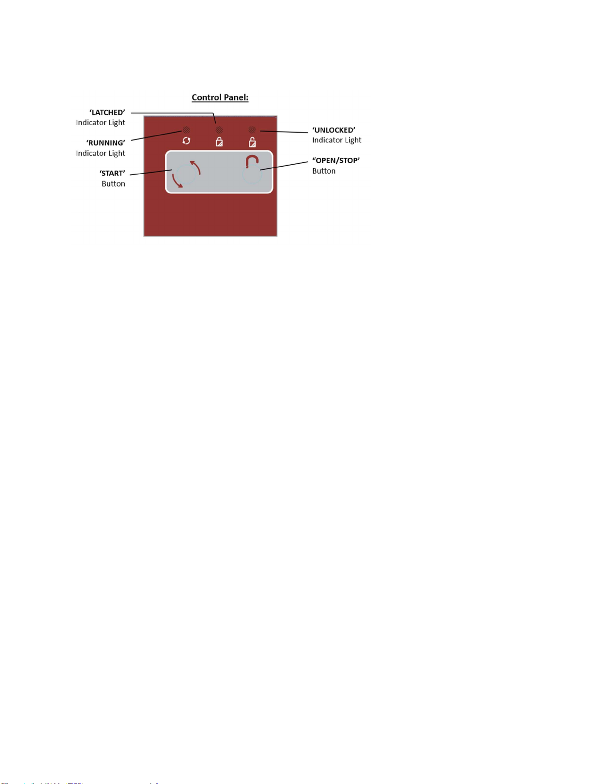
1. Unlock the centrifuge by pushing the ‘OPEN / STOP’ button and unlatch and open the lid.
CAUTION: Unplug the centrifuge from the electrical outlet to eliminate the possibility of electrical shock
or other injury.
2. Remove the test tube holders.
3. Remove the nut in the center of the rotor by turning it counterclockwise (a tool may be required).
4. The rotor is sitting on a cone-shaped adapter. Pull the rotor up and off of this adapter.
TO INSTALL THE ROTOR
1. Place the rotor back onto the cone-shaped adapter. You may need to turn the rotor slightly to line it up
properly.
2. The rotor should slide onto the rotor cone freely.
3. Once a proper fit has been achieved, replace the nut and turn it until it is hand-tight, (a tool may be
required).
4. Replace the tube holders and verify that they are seated properly.
5. It is recommended that the initial setup procedures be performed to ensure that the rotor has been
installed correctly and that no damage has been done to the centrifuge during either the rotor installation
or possible rotor chamber cleaning. See page 6 for this procedure.
CARE AND PREVENTATIVE MAINTENANCE
With proper care and maintenance your centrifuge will provide years of laboratory service. For proper care, the
following steps should be taken:
1. Provide Adequate Ventilation: For cooling purposes, the Model 642E draws in ambient air through the air
intake cover on the top of the lid and exhausts this air in the rear of the base. The centrifuge should be
placed on a hard smooth surface for good air circulation.
2. Always Spin Balanced Loads: Make certain that you are always spinning a balanced load. The Model 642E
has a unique counter balanced motor mounting design which, along with its rubber suction feet, produces
excellent vibration dampening. However, out–of–balance loads may break glass test tubes and may
produce unsatisfactory separation results. Proper load balancing will improve sample separation and
extend the life of the centrifuge. Refer to page 10 on balanced loads for additional information on
balancing the load.
3. Keep the Tube Holders Clean: NOTE: Always follow the safety guidelines of your laboratory to properly
clean up and/or dispose of materials in the event that a substance known to be potentially toxic,
radioactive or contaminated with a pathogenic microorganism is spilt in or on the centrifuge. Small glass
fragments left in the tube holder after a tube breakage may adhere to the next test tube inserted in that
holder. When this tube is handled, these fragments may puncture protective gloves and lacerate the
operator’s fingers or hand. Remaining fragments may provide stress points on subsequent tubes and
result in additional breakage. If a tube breakage occurs, carefully remove the tube holder. Properly
dispose of the sample and tube fragments and thoroughly clean both the inside and outside of the tube
holder.
4. Motor and Electrical Maintenance: The Model 642E uses a brushless permanent split capacitor AC motor.
It should not need routine servicing for the life of the centrifuge. The electrical components are selected
for high reliability and should not need routine service.
5. Tube Holder Replacement: It is recommended that the tube holders be replaced after 24 months of use.
Inspect tube holders regularly for cracks. If cracks are discovered, replace immediately.
6. Remove Accessories Before Moving: All tube holders, samples, and caps must be removed from the rotor
chamber before transporting or storing the centrifuge to prevent damage and injury.

Drucker Diagnostics – Customer Service: +1-814-692-7661 – CustomerService@DruckerDiagnostics.com | Page 9
CLEANING AND DISINFECTION
To prolong the life of the centrifuge cleaning and disinfection is recommended every six months, or whenever
there is a spillage or tube breakage. Contaminants must be removed immediately, or corrosion and premature
degradation of components can occur.
1. Unplug the centrifuge before cleaning.
2. Apply cleaning solutions with a towel or cloth. Do not submerge the centrifuge in water or other cleaning
solutions as this will cause damage and void the warranty.
3. ONLY isopropyl alcohol, soap and water, or a 10% (5500 PPM) bleach solution should be used for cleaning
and disinfection of the centrifuge and accessories.
4. All surfaces must be dried immediately after cleaning and disinfecting.
5. TBQ Germicidal products shall not be used, as they will cause damage to the centrifuge and void the
warranty.
6. The use of fully/partially halogenated hydrocarbons, ketones, esters, ethers, benzyls, ethyl benzenes, and
all other chemicals not prescribed by the manufacturer shall not be used as they may cause damage to
the rotor chamber, rotor, tube holders, accessories and centrifuge exterior and void the warranty.
7. It may be necessary to remove the rotor and clean the rotor chamber. Follow the instructions on page 8
to remove and reinstall the rotor.
TROUBLESHOOTING
Note: The latch must be turned completely clockwise to its stop position in order for the centrifuge to operate.
Problem: The rotor does not spin freely.
Solution:
o Make sure nothing has fallen into the rotor chamber
o If there is nothing obstructing the rotor, the rotor may be damaged. Contact Drucker Diagnostics for
further assistance.
Problem: Excessive noise when the machine is running.
Solution:
o Check to see that the load is balanced.
o Make sure that nothing has fallen into the rotor chamber.
o Make sure that the nut in the center of the rotor is tight.
o Have a technician test the motor and replace it if necessary.
Problem: The Centrifuge does not spin.
Solution:
o Check the electrical outlet
o Make sure the lid latch is turned completely clockwise to its stop position. When the lid is closed properly,
the latch light on the control panel will illuminate.
o Check the circuit breaker switch at the bottom left of the machine. If the switch is white, the breaker has
tripped. Contact Drucker Diagnostics for further assistance.
o The printed circuit board may be damage. Have a technician test and replace the circuit board if
necessary.
Problem: The latch light does not come on when the lid is closed.
Solution:
o Make sure that the unit has power.
o Make sure the lid latch is turned completely clockwise to its stop position. The latch makes contact with a
switch underneath the front top of the cabinet. If this switch is not activated. The light will not tur on the
machine will not run

Drucker Diagnostics – Customer Service: +1-814-692-7661 – CustomerService@DruckerDiagnostics.com | Page 10
Problem: The machine does not unlock after a run has completed.
Solution: The lid should remain locked until the rotor has nearly come to a complete stop and then unlock for 60
seconds. If additional unlock time is needed, press the ‘OPEN / STOP’ button with the machine plugged in and the
rotor stopped. If the lid remains locked after this and will not unlock, the electronics may have been damaged.
Contact Drucker Diagnostics for further assistance. To access the rotor chamber, follow the procedure on Page 14,
“Emergency Rotor Chamber Entry”.
Problem: The run time is not set to the desired length.
Solution: Check the run preset by following the instructions on page 8. If the preset is not the desired length,
follow the procedure on the same page to change the run preset time.
EMERGENCY ROTOR CHAMBER ENTRY
In the event of power failure, it may be impossible to unlock the lid by conventional means. In this case, entry into
the rotor chamber may be made by removing the latch label and using a pen to manually disengage the locking
mechanism (see photo). Pull the mechanism towards the control panel and then
unlatch and open the lid. If the unit is damaged, contact your authorized dealer or
Drucker Diagnostics.
CALIBRATION TESTING
It is recommended that the top speed be tested every two years for continued safe
operation. Contact Drucker Diagnostics for further information or testing availability.
SAFETY
The Model 642E complies with US, Canadian, and European Safety standards.
Lid Safety Switch: The Model 642E lid is secured to the top of the cabinet by a latching knob and pawl system.
When the knob is rotated clockwise, the pawl grips the underside of the cabinet opening and prevents the lid from
opening. A mechanical stop positions the pawl and prevents it from rotating completely. When rotated to the stop
position, the pawl makes contact with a micro–switch mounted underneath the cabinet top. The lid safety switch
prevents the centrifuge from operating while the lid is open. An indicator light on the front of the machine will
light up when the lid has been latched properly.
Lid Safety Interlock System: In addition to the Lid Safety Switch, the Model 642E has a true “0 RPM” lid locking
system. The lid safety locking system keeps the lid locked at all times when the rotor is in motion (even during
power failure). The centrifuge will not allow entry into the rotor chamber unless the centrifuge has power and the
rotor is stopped. To open the lid, make sure that the centrifuge is plugged in and, with the rotor stopped, press the
‘OPEN / STOP’ button.
Note: After the centrifuge has started spinning, it may be possible to rotate the lid knob enough to cause
the pawl to lose contact with the lid safety switch. If this happens, the centrifuge motor may lose power,
but the lid will still remain locked. If the knob is accidentally moved and this situation should occur, rotate
the knob fully clockwise to its stop position and the centrifuge will resume operation.
Circuit Breaker: The Model 642E is protected with a 4 Amp circuit breaker located at the rear of the machine
mounted to the base. Any electrical short circuit will cause the breaker to cut power to the machine.

Drucker Diagnostics – Customer Service: +1-814-692-7661 – CustomerService@DruckerDiagnostics.com | Page 11
REPLACEMENT PARTS
Part No. Description
7724037K Foot, rubber (Pack of 4)
7751068 Switch, lid safety
7786061 Rotor, six-place, horizontal
7735049 Motor, 1/30 H.P., 115 V.A.C. permanent split
capacitor
7729006 Capacitor, 4uF, 250V A.C.
7717051 Electronic timing and locking board
7751043 Circuit Breaker
7760002 Power cord
03-1-0008-0016 Pawl, latch, lid
03-1-0008-0009 Knob, latch, lid
7724071K Hinge, friction (Pack of 2)
7732018 Seal, lid gasket
7713079K Universal Tube Holder for all tubes 75-100 mm
(Pack of 6)
02-002-1-0024 Lid Assembly
03-0-0003-0813 Front Panel Label, Boekel
00-100-100-009 6 Series Soft Button Replacement Kit
AVAILABLE ACCESSORIES
0.5 to 1 mL Tube
Adapter (Pack of 6)
p/n 7713068K
1.5 to 2 mL Tube
Adapter (Pack of 6)
p/n 7713065K

Drucker Diagnostics – Customer Service: +1-814-692-7661 – CustomerService@DruckerDiagnostics.com | Page 12
This operator’s manual is part number 03-0-0002-0267 Rev. B
To access previous manuals, please click on relevant link below.
Revision A
FDA LISTED
INSTRUCTIONS FOR DISPOSAL OF WEEE BY USERS IN THE EUROPEAN UNION
This product must not be disposed of with other waste. Instead, it is the user’s responsibility to dispose of
their waste equipment by handing it over to a designated collection point for the recycling of waste
electrical and electronic equipment. The separate collection and recycling of your waste equipment at the
time of disposal will help to conserve natural resources and ensure that it is recycled in a manner that
protects human health and the environment. For more information about where you can drop off your
waste equipment for recycling, please contact your local city office, waste disposal service, or where you
purchased the product.
Designed, built, and supported in the USA
200 Shady Lane, Suite 170 • Philipsburg, PA 16866
+1-866-265-1486 (U.S. only) • +1-814-692-7661 • www.druckerdiagnostics.com
Protected by U.S. Patents #6,811,531, & #D718463 Other Patents Pending

Drucker Diagnostics – Service clientèle : +1-814-692-7661 – CustomerService@DruckerDiagnostics.com | Page 13
642E
Manuel d’utilisation

Drucker Diagnostics – Service clientèle : +1-814-692-7661 – CustomerService@DruckerDiagnostics.com | Page 14
TABLE DES MATIÈRES
Symboles............................................................................................................................................................. 15
Mise en garde et Avertissements de Sécurité .................................................................................................... 16
Description du modèle ....................................................................................................................................... 17
Utilisation prévue ............................................................................................................................................... 17
Équipement fourni .............................................................................................................................................. 17
Caractéristiques .................................................................................................................................................. 17
Garantie .............................................................................................................................................................. 18
Caractéristiques Générales ................................................................................................................................. 18
Emplacement installation ................................................................................................................................... 18
Procédure D'installation Initiale ......................................................................................................................... 19
Panneau de configuration .................................................................................................................................. 20
Vérification de la Durée et du Frein Préréglés .................................................................................................... 20
Modification de la Durée et du Frein Préréglés .................................................................................................. 21
Fonctionnement ................................................................................................................................................. 21
Centrifugation de charges équilibrées ................................................................................................................ 22
Retrait et Installation Du Rotor .......................................................................................................................... 22
Retirez le rotor ............................................................................................................................................... 22
Installation du rotor ....................................................................................................................................... 22
Entretien préventif ............................................................................................................................................. 23
Nettoyage et Désinfection .................................................................................................................................. 24
Dépannage .......................................................................................................................................................... 24
Entrée D'urgence de la Chambre du Rotor ......................................................................................................... 25
Tests d'étalonnage .............................................................................................................................................. 25
Sécurité ............................................................................................................................................................... 25
Pièces de Rechange ............................................................................................................................................ 26
Accessoires Disponibles ...................................................................................................................................... 26

Drucker Diagnostics – Service clientèle : +1-814-692-7661 – CustomerService@DruckerDiagnostics.com | Page 15
Symboles
Symbole Définition Utilisation
Mise en garde
Mise en garde pour les risques liés à la sécurité.
Risque potentiel de blessures corporelles ou de dommages à l'instrument
s'il est mal manipulé. Consultez le manuel avant de continuer.
Fabriquant Fabriquant de référence.
Symbole de recyclage
des produits électriques
et électroniques
Recycler uniquement comme déchets électroniques. Ne pas jeter avec
les autres déchets
Conforme à la
norme RoHS Conforme aux normes environnementales RoHS
Homologation MET Indique la conformité avec les normes et les réglementations de sécurité
spécifiées.
Marquage CE Indique la conformité avec les directives et les réglementations
européennes spécifiées.
HOMOLOGUÉ
PAR LA FDA Homologué par la FDA Indique que le produit a été correctement homologué auprès de la
FDA.
Certification ISO Indique la conformité avec les normes de qualité et les systèmes de
gestion de la qualité.

Drucker Diagnostics – Service clientèle : +1-814-692-7661 – CustomerService@DruckerDiagnostics.com | Page 16
MISE EN GARDE ET AVERTISSEMENTS DE SÉCURITÉ
Cet appareil est destiné à être utilisé par un personnel correctement formé qui a lu attentivement le manuel
d’utilisation et maîtrise le fonctionnement de l’appareil. [Reportez-vous à la méthode de laboratoire clinique
définie par le fabricant du récipient à échantillons ou établie par la technologie médicale pour connaître les
utilisations prévues du produit.]
AVERTISSEMENT : Pour la sécurité de l’utilisateur et du personnel de service, il convient d’être prudent lors de
l’utilisation de cette centrifugeuse si vous manipulez des substances connues comme étant toxiques,
radioactives ou contaminées par des micro-organismes pathogènes. Lorsque des matériaux du groupe de
risque II sont utilisés (tels qu’identifiés dans le « Manuel de sécurité biologique en laboratoire » de
l’Organisation mondiale de la Santé), un BioSeal doit être utilisé. L'accessoire Bio-Seal pour le modèle est le
bouchon de protection non aérosol avec les porte-tubes appropriés (contactez Drucker Diagnostics pour
l'achat). Dans le cas où des matériaux d’un groupe de risque plus élevé sont utilisés, il est nécessaire d’assurer
plus d’un niveau de protection.
Il est interdit d’utiliser des matériaux inflammables ou explosifs ainsi que de matériaux qui ont une réaction
chimique vigoureuse.
Pour votre sécurité et la durabilité de votre machine, ne transportez jamais de centrifugeuse avec des porte-
tubes et la stockez jamais à l'intérieur de la machine.
Inspectez la centrifugeuse pour vérifier que le boîtier, le couvercle, le rotor, ou les portes-tubes ne présentent
pas de fissures ou de dommages physiques. Tout dommage peut entraîner un fonctionnement dangereux.
Cessez d’utiliser l’appareil tant que les réparations nécessaires n'ont pas été effectuées.

Drucker Diagnostics – Service clientèle : +1-814-692-7661 – CustomerService@DruckerDiagnostics.com | Page 17
DESCRIPTION DU MODÈLE
Le modèle 642E est une centrifugeuse horizontale à commande électronique à fonctionnement continu avec un
système de verrouillage de sécurité du couvercle. L'appareil est contrôlée par une minuterie électronique à
bouton-poussoir qui a été préréglée pendant dix (10) minutes, pour des durées de rotation précises et une facilité
d'utilisation. Vous pouvez visualiser les échantillons en toute sécurité à travers le couvercle transparent. Pendant
le fonctionnement, le système de verrouillage de sécurité limite l'entrée dans la machine. Le modèle 642E dispose
d'un panneau de commande éclairé qui affiche l'état de la machine, facilement visible à distance.
Cette centrifugeuse de laboratoire à usage général est conçue pour faire fonctionner également d’autres récipients
approuvés remplis de produits chimiques (ininflammables, non explosifs, non volatils et non hautement réactifs
uniquement) et des échantillons environnementaux
UTILISATION PRÉVUE
Centrifugeuse de laboratoire à usage général destinée à la séparation des fluides en fonction de la densité à
travers l'accélération centripète.
ÉQUIPEMENT FOURNI
Un rotor (1) horizontal à six places
P/N 7786061
Six (6) porte-tubes 75-100 mm
universels
P/N 7713079
Le rotor et les accessoires sont prévus pour une fréquence de rotation de 4 000 T/M.
Pour les accessoires en option, voir la dernière page de ce manuel.
CARACTÉRISTIQUES
Conception de rotor horizontal pivotant incorporant un porte-tube unique qui produit des échantillons
séparés horizontalement et fait tourner des tubes de 75 et 100 mm
La conception du flux d'air Cool–Flow empêche la surchauffe des échantillons
Construction en acier de gros calibre pour la sécurité et la durabilité
L'interrupteur de sécurité du couvercle empêche la centrifugeuse de fonctionner si le couvercle n’est pas
fermé et verrouillé
Verrouillage automatique du couvercle de sécurité, enclenché chaque fois que le rotor est en mouvement
Rotor amovible pour un nettoyage facile
Moteur CA à condensateur divisé permanent sans balais
Un couvercle transparent permet l’observation sécurisée des échantillons et l’étalonnage optique de la
vitesse.
Fonctionnement temporisé à commande électronique (voir p. 6)
Fonctionnement par bouton-poussoir
Témoins lumineux :
Couleur Statut
« EN COURS DE
FONCTIONNEMENT »
Vert Le moteur est mis sous
tension
« VERROUILLÉ » Jaune Le couvercle est fermé
et verrouillé
« DÉVERROUILLÉ » Rouge Le système de
verrouillage est désactivé

Drucker Diagnostics – Service clientèle : +1-814-692-7661 – CustomerService@DruckerDiagnostics.com | Page 18
GARANTIE
Drucker Diagnostics garantit que la fabrication et les pièces de cette centrifugeuse sont exempts de défauts
pendant deux ans.
CARACTÉRISTIQUES GÉNÉRALES
Vitesse nominale (horizontale) 3 380 (+/- 100) T/M
FCR nominale (horizontale) 1 600 (+/- 90) xg
Capacité maximale (horizontale)
60 mL (6 x 10 mL)
Dimensions globales (H x L x P) 9 po. x 12 po. x 14 po.
Moteur de la centrifugeuse: Moteur p.s.c., 1/30 HP
Durée de démarrage maximum 10 secondes
Disjoncteur de protection 4 A. réinitialisable
Minuteur électronique, 1 à 30 minutes
réglé sur 10 minutes, +/– 1%
Exigence actuelle 1,5 A
Tension requise 115 (+/- 10) Volts
Fréquence 60 Hz
Poids 11 lbs
Toute utilisation autre que celle spécifiée par le Fabricant est expressément interdite.
La densité maximale de l'échantillon est de 1,15 grammes/mL (densité de l'eau = 1,0 grammes/mL)
EMPLACEMENT INSTALLATION
1. Déballez la centrifugeuse et vérifiez que tout l'équipement fourni est présent.
2. Sélectionnez un emplacement de configuration qui répond aux critères suivants :
a. Une hauteur intérieure de 20 po (50,8 cm) est nécessaire pour ouvrir le couvercle.
b. L'enveloppe de dégagement est l'espace autour de la centrifugeuse qui est requis pour la
sécurité. Sélectionnez un emplacement de configuration qui permettra une enveloppe de
dégagement d'au moins 24po x 24 po (avec la centrifugeuse au centre). Aucune personne ou
matière dangereuse ne doit être autorisée dans l'enveloppe de dégagement pendant le
fonctionnement. La durée passé par l’utilisateur à l’intérieur de l’enveloppe doit être limité au
durée nécessaire au chargement, au déchargement et au fonctionnement de la centrifugeuse
uniquement.
c. Une ventilation adéquate est nécessaire pour éviter la surchauffe des échantillons ainsi que la
défaillance prématurée de la centrifugeuse. Choisissez un endroit qui permet une circulation
libre de l’air et où la température demeure entre et °C.
d. La centrifugeuse est conçue pour être fixée à la surface de fonctionnement par quatre pieds-
ventouse. Aucun réglage n'est nécessaire pour niveler la centrifugeuse ; cependant, la surface
doit être plane et horizontale.
e. Assurez-vous que la prise est toujours à portée de main car le cordon d'alimentation est le
moyen de déconnexion d'urgence !
Table of contents
Languages:
Other Boekel Laboratory Equipment manuals

Boekel
Boekel RapidFISH 240200 User manual

Boekel
Boekel 302000 User manual

Boekel
Boekel Bambino 230301 User manual

Boekel
Boekel Rocker II User manual

Boekel
Boekel Slide Moat 240000 User manual

Boekel
Boekel InSlide Out 241000 User manual

Boekel
Boekel Tap Dancer User manual

Boekel
Boekel DASH Flex 24 User manual

Boekel
Boekel FLASK DANCER User manual

Boekel
Boekel UV CROSSLINKER User manual