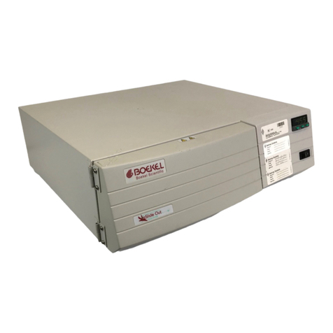
Boekel RapidFISH 240200 User manual

N2400362 Rev. 1 04/16
RapidFISH
Models 240200 and 240200-2
Operating Instructions

Page 2 of 13
Table of Contents
1.0 Safety ...................................................................................... 3
2.0 Intended Use of Product........................................................ 4
3.0 Installation .............................................................................. 4
3.1 Unpacking the Unit.........................................................................4
3.2 Set up...............................................................................................4
4.0 Control Panel Overview......................................................... 4
5.0 Operation................................................................................ 5
5.1 Turning the Unit On........................................................................5
5.2 Modes of Operation........................................................................6
6.0 Calibration.............................................................................. 7
7.0 Technical Specifications ....................................................... 9
8.0 Additional Accessories Available for Purchase ................ 10
9.0 Fault Diagnosis ..................................................................... 10
10.0 Maintenance and Service .................................................. 11
10.1 Cleaning........................................................................................11
10.2 Decontamination..........................................................................11
10.3 Replacement of Fuses..................................................................11
11.0 Contrast Adjustment ............................................................ 12
12.0 Warranty ............................................................................... 12
13.0 Service .................................................................................. 13

Page 3 of 13
1.0 Safety
The following symbols marked on the equipment mean:
Caution: Read these operating instructions fully before use and pay
particular attention to sections containing this symbol.
Attention: Suivre attentivement les instructions avant l’usage et
prêtez une attention particulière aux sections comportant ce
symbole.
Caution: Surfaces can become hot during use.
Attention: Les surfaces peuvent devenir brûlantes pendant l’usage.
Always observe the following safety precautions.
•Read this entire manual before using the slide hybridization oven.
•Use only approved accessories. Do not modify system or
components. Any alterations or modifications to your incubator
may be dangerous and will void the warranty.
•Intrinsic protection may be impaired if the unit is used in a
manner which is not specified in this manual.
•Do not position the equipment so that it is difficult to operate the
disconnecting device.
•Use only as specified by the operating instructions or the intrinsic
protection may be impaired. After transport or storage in humid
conditions, dry out the unit for 48 hours before connecting it to
the supply voltage. During drying out, the intrinsic protection
may be impaired.
•Connect only to a power supply that provides a safety ground
terminal.
•Do not check temperature by touch. Use the temperature
display or a thermometer.
•Do not touch surfaces that become hot.
•Ensure that the power supply cord plug is easily accessible
during use.
•Do not block or restrict ventilation slots. Allow at least 3”
clearance around the entire unit.
•If liquid is spilled inside the unit, disconnect it from the power
supply and have it checked by a competent person.
•This product must be used with a power supply cord that is rated
for a minimum temperature of 90°C and that complies with
National and Local certification requirements.
•Do not use with flammable, corrosive, or hazardous material.
•Never leave the unit unattended.

Page 4 of 13
•Do not mount equipment on a surface of flammable material
due to a hazard that could be caused by hot items falling from
the equipment when the door is opened.
2.0 Intended Use of Product
The Boekel Scientific RapidFISH is designed for use in slide
hybridization and to simplify Flourescent In-Situ Hybridization (FISH)
procedures for FFPE samples, cell suspensions and other tissue
preparation procedures. FISH testing is used worldwide to identify
markers in the form of DNA/RNA.
3.0 Installation
3.1 Unpacking the Unit
Remove the packing materials carefully, and retain for future
shipment or storage of the unit. Inspect for damage. Report all
shipping damage to the carrier immediately. Shipping damage is
covered by the carrier and repair/replacement for shipping
damages must be coordinated through the carrier. Complete and
return the Warranty Registration Card or you may also complete this
Warranty Card online at www.boekelsci.com.
The package should contain:
•RapidFISH
•Power line cord
•Operating Instructions
•One tray assembly
3.2 Set up
Place the RapidFISH on a flat and stable surface, preferably away
from drafts with at least 3” clearance around unit. Ensure that the
surface on which the unit is placed will withstand the radiated heat
produced by typical laboratory incubators and ovens. Units are
stackable and can be stacked without impeding airflow or
ventilation. If stacking units on top of each other, ensure
compliance with local codes and safety in doing so.
Fit the power line cord into the IEC power socket on the rear of the
unit. Plug the power cord into a power supply that matches the
voltage listed on the serial/electrical information label on the rear of
the unit.

Page 5 of 13
4.0 Control Panel Overview
A. Program –Cycles through the different programmed steps, “S1”,
“S2”, “S3”, and “HT”.
B. Set –Allows changing of time and temperature values. Used to
toggle between time adjustment and temperature adjustment.
C. Start/Stop/Reset –Starts, stops, and resets the programmed runs.
Single press of the button will start, stop, or resume the programs.
Pressing and holding will reset the sequence. (Programs follow the
sequence of S1 S2 S3.)
D. Up/Down Arrow Keys –Used to increase or decrease the selected
variable. Press and hold for rapid change.
E. LCD Display –Shows set temperature, program number, actual
temperature, time remaining, and heating indicator.
F. When the unit is in full heat mode, a white square on the far right of
the lower display line will illuminate. When the heater is maintaining
temperature, the white square will flash. When the heater is off, the
white square is no longer illuminated.
5.0 Operation
5.1 Turning the Unit On
5.1.1 Using the power cord provided with the unit, connect
the female end directly into AC socket on rear of unit.
Make sure power switch on rear of unit is off (0).
Connect male end of power cord to grounded
electrical outlet.

Page 6 of 13
5.1.2 Turn unit on by switching the power switch to the on
position (I). The unit will go through a brief startup test,
which includes displaying the software revision level.
5.1.3 After the start up test is completed, the unit will switch
to normal operation mode. The LCD display will show
the Actual Temperature of the chamber as well as the
Setpoint value. The unit will start to achieve setpoint
temperature without any operator intervention.
5.2 Modes of Operation
5.2.1 The unit can be run in Hold Temperature (HT) or
Program mode, which allows up to 3 steps of time and
temperature values to be run sequentially.
5.2.2 The Program key cycles through the different programs
(S1 S2 S3 HT S1 and so forth).
5.2.3 In HT mode, the RapidFISH will hold temperature at the
desired setpoint.
5.2.3.1 Press Set key to allow changing of
temperature setpoint.
5.2.3.2 Use Up and Down arrow keys to change
value.
5.2.3.3 Unit will maintain temperature at setpoint until
another mode is selected or the temperature
setpoint is changed.
5.2.4 In Program mode, the unit will move from step 1 (S1) to
step 2 (S2) then to step 3 (S3) in succession and beep
when the entire program has completed.
5.2.4.1 The Program key cycles through the different
programmed steps.
5.2.4.2 Press Set key to allow changing of values. Use
Up or Down key to increment or decrement
value.

Page 7 of 13
5.2.4.3 Press Set key again to toggle between
adjusting set temperature and time
remaining.
5.2.4.4 Once all program steps are entered, pressing
Start/Stop/Reset will begin the program.
Pressing Start/Stop/Reset again will pause the
program. Pressing and holding
Start/Stop/Reset will reset the program to S1.
5.2.4.5 Temperatures can be adjusted from ambient
or 18°C (whichever is greater) to 75°C.
5.2.4.5.1 S2 and S3 can be turned off in the
program by adjusting the
temperature value down to the
value below 18.0°C, which will
display the word “OFF”.
5.2.4.6 Times can be adjusted from 000:01 to 999:59
(mmm:ss).
5.2.4.6.1 S2 and S3 can be set to hold
indefinitely in the program by
adjusting the time value down to the
value below 000:01, which will
display the word “HOLD”.
5.2.4.7 Upon completion of all steps, unit will beep
and flash time as 000:00. Temperature will
remain at last set temp. Holding
Start/Stop/Reset resets the cycle and shows S1
with its time and temperature.
6.0 Calibration
6.1 Turn the unit off and allow the interior surfaces to reach
ambient temperature. Place a certified reference
thermometer in the center of the tray. Ensure the
thermometer is not touching any parts of the tray.
Boekel calibration kit part number 240550 can be used
to assist in the setup.

Page 8 of 13
6.2 Turn the unit on and simultaneously press the Up and
Down arrow keys and the Program key to enter
calibration mode.
6.3 Allow the unit 60 minutes to achieve calibration
setpoint of 40.0°C. Once the 60 minutes have elapsed,
the unit will beep once and flash the 40.0°C text on the
display. Use the Up and Down arrow keys to match the
displayed value to the temperature of the calibrated
probe. Press Set key to confirm temperature reading.
6.4 Allow the unit 60 minutes to achieve new calibration
setpoint of 60.0°C. Once the 60 minutes have elapsed,
the unit will beep once and flash the 60.0°C text on the
display. Use the Up and Down arrow keys to match the
displayed value to the temperature of the calibrated
probe. Press Set key to confirm temperature reading.
6.5 The unit will return to the main screen and can be
turned off at this point. Allow the unit to cool before
touching any internal surfaces. Once this is done, the
probe setup can be removed and normal operation of
the slide hybridization oven can be resumed.

Page 9 of 13
7.0 Technical Specifications
This equipment is for indoor use and will meet its performance
specifications within the ambient temperature range of 10°C to
30°C, with maximum relative humidity of 80%. Installation category
II (transient voltages). Pollution degree 2 in accordance with IEC
664. For operation at altitudes of up to 6500 feet (2000 meters).
Temperature Range
Ambient +5.0°C to 75°C
Stability
±0.2°C
Accuracy
±0.5°C
Temperature Display Resolution
0.1°C
Supply Ratings
Model # 240200
Model # 240200-2
115 V AC ±10%; 50/60 Hz; 2.0 Amps
230 V AC ±10%; 50/60 Hz; 1.0 Amps
Environmental Conditions for
Operation:
Intended for indoor use only.
Temperature: 10°C to 30°C
Humidity: 10% to 80% non-condensing
Atmospheric Pressure: 99.5 to 103.5kPa
Overall Dimensions (W x D x H)
11” x 16” x 8”

Page 10 of 13
8.0 Additional Accessories Available for Purchase
Item #
Description
240550
Calibration Kit
9.0 Fault Diagnosis
Symptom
Possible Cause
Action Required
Unit does not operate
a. Unit is not switched
on
b. Unit is not plugged
into a power supply
c. Fuses blown
d. Power supply failure
a. Switch the unit on
b. Plug in, switch on
c. Replace fuses (see
Section 10.2)
d. Check that other
electrical appliances on
the same circuit are
working
Chamber temperature
does not heat when
expected
a. Actual temperature
is higher than Set
temperature
b. Temperature
control circuit fault
c. Circulation Fan
failure
a. Check set temperature
b. Have unit checked by a
competent service
person
c. Have unit checked by a
competent service
person
Temperature continues
to rise when not
expected
a. Actual temperature
is lower than Set
temperature
b. Temperature
control circuit fault
c. Circulation Fan
failure
a. Check set temperature
b. Have unit checked by a
competent service
person
c. Have unit checked by a
competent service
person
Unit turns on but no text
is seen on the display
d. Contrast adjusted
too far up or down
d. Adjust contrast up or
down until text
becomes visible (see
Section 11)

Page 11 of 13
10.0 Maintenance and Service
All Boekel laboratory products are designed to comply with
IEC61010-1. No routine maintenance is required.
10.1 Cleaning
Prior to cleaning, turn power off, disengage power cord and allow
unit to return to ambient temperature, if still warm. Both the inner
chamber and outer housing can be cleaned with a cloth
dampened with water and mild soap. Do not use spray cleaners
that might leak through the chamber at the seams and damage
electrical components. Do not use chlorine-based bleaches or
abrasives, as they will damage the stainless steel interior. Do not
immerse the slide hybridization oven in water.
10.2 Decontamination
The end user shall ensure that:
•appropriate decontamination is carried out if hazardous
material is spilled onto or into the equipment,
•no decontamination or cleaning agents are used which
could cause a hazard as a result of a reaction with parts of
the equipment or with material contained in it, and
•the manufacturer is consulted if there is any doubt about the
compatibility of decontamination or cleaning agents with
parts of the equipment or with material contained in it.
10.3 Replacement of Fuses
There are two supply fuses located in the fuse drawer. To change
the fuses:
•Turn power switch to the off (O) position
•Disconnect the unit from the power supply
•Remove the line cord from the power entry module on the back
of the unit (Figure 2 –below)
•Pull back on the fuse drawer catch (located on top of power
entry module)
•Pull out the fuse drawer
•Check and replace with the correct fuses if necessary. The fuses
must be 5mm x 20mm Quick Acting, rated at 2.0amp 250V for
115V units, and 1.0amp 250V for 230V units.

Page 12 of 13
•Push the drawer back in and reconnect the unit to the power
supply.
•Verify correct voltage reading is displayed in the fuse window
located above the on/off switch (illustrated below) after fuse
replacement before connecting to the power supply.
11.0 Contrast Adjustment
The contrast of the display can be adjusted by holding the Program
key and pressing the Up or Down arrow to adjust the contrast up or
down, respectively. Care should be taken to avoid adjusting
contrast so far in one direction that the text on the display becomes
unreadable.
12.0 Warranty
When used in laboratory conditions and according to these
operating instructions, Boekel warrants this product to be free of
defective material and workmanship for a period of two years from
the date of manufacture. The liability of Boekel for any defective
equipment during the warranty period shall be limited to the repair
of such equipment or replacement thereof without charge for parts
or labor.

Page 13 of 13
13.0 Service
It is required to obtain a Returned Material Authorization (RMA)
number before any Boekel products are returned for any reason. A
Decontamination Certificate must be completed, signed by the
user, and returned to Boekel Scientific prior to receiving the RMA
number. Please consult the manufacturer or his agent if there is any
doubt about the compatibility of decontamination or cleaning
agents. Please be sure to mark the outside of the returned goods
package with this RMA number to ensure prompt handling.
Boekel Scientific
855 Pennsylvania Boulevard
Feasterville, PA 19053
Phone: (215) 396-8200 or (800) 336-6929
Fax: (215) 396-8264
This manual suits for next models
1
Table of contents
Other Boekel Laboratory Equipment manuals

Boekel
Boekel Rocker II User manual

Boekel
Boekel 642E User manual

Boekel
Boekel 302000 User manual

Boekel
Boekel Bambino 230301 User manual

Boekel
Boekel Slide Moat 240000 User manual

Boekel
Boekel UV CROSSLINKER User manual

Boekel
Boekel FLASK DANCER User manual

Boekel
Boekel Tap Dancer User manual

Boekel
Boekel InSlide Out 241000 User manual

Boekel
Boekel DASH Flex 24 User manual