8
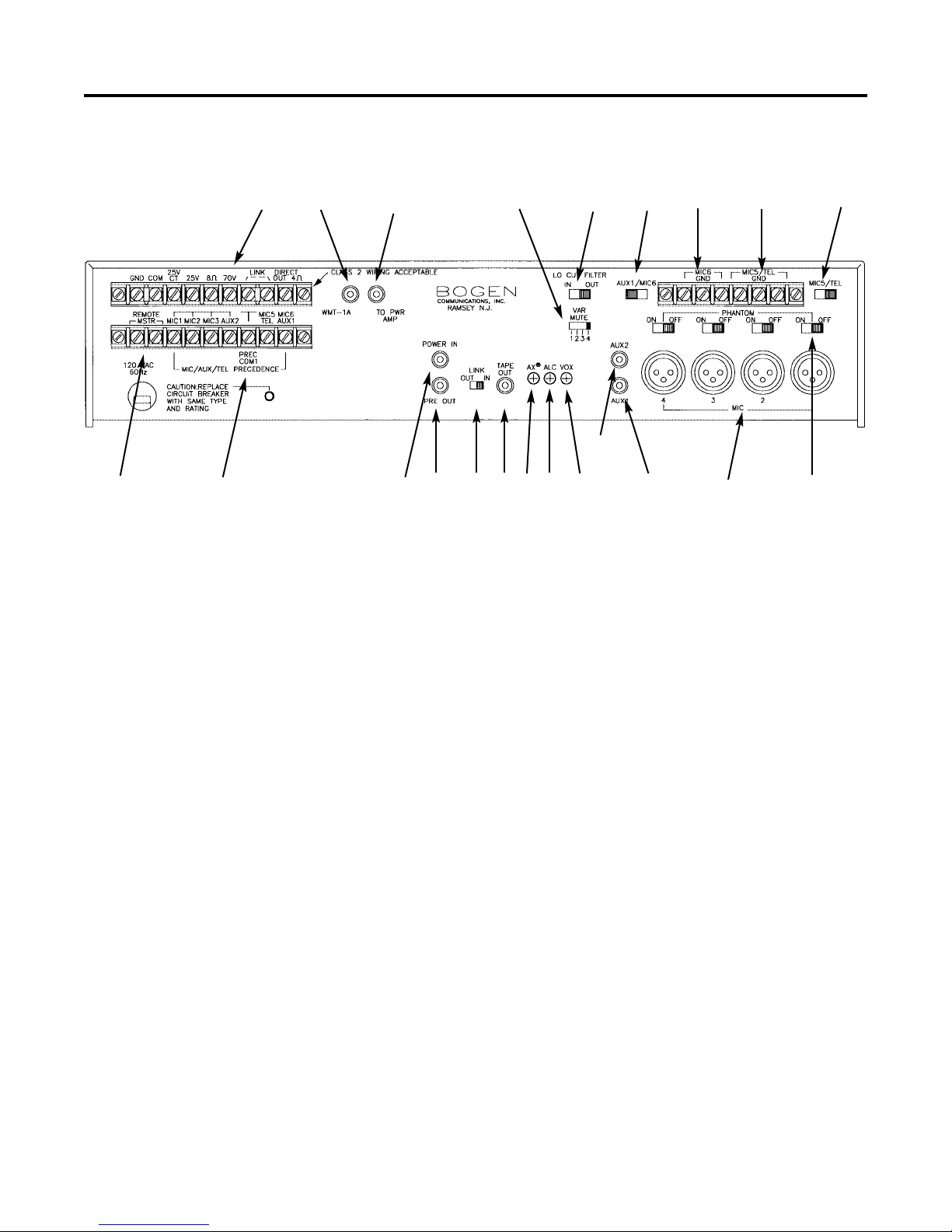
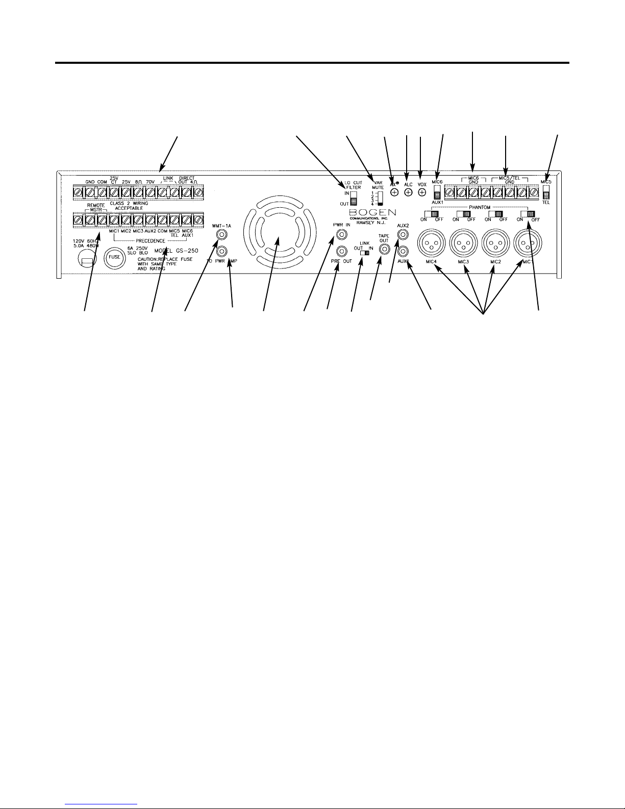
Output Terminal Strip
Speaker systems are connected directly to the speak-
er output terminals on the rear panel. Connect one
speaker lead to the COM terminal and the other to the
terminal corresponding to the impedance of the speak-
er system. Select only one of the output types.
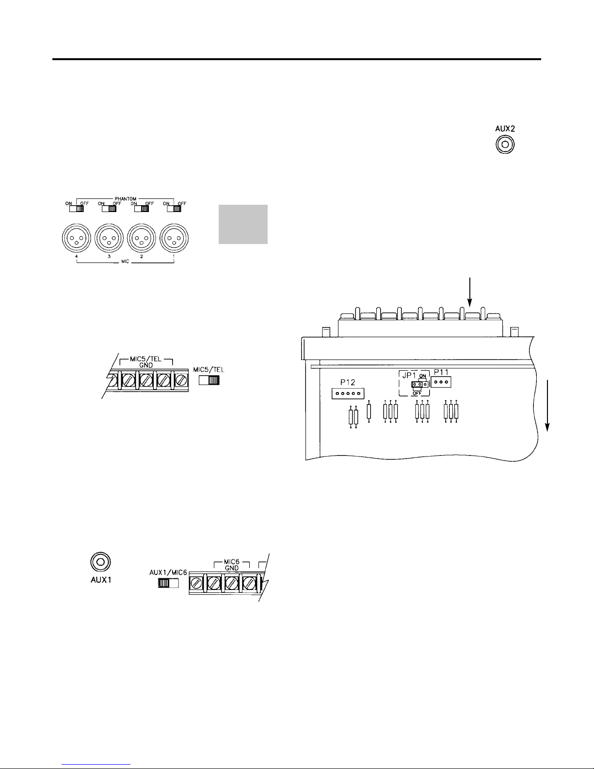
For ground-referenced output operation unbalanced
systems), leave the shorting clip between COM and
GND. For special applications that require floating out-
puts balanced systems), remove the shorting clip
between COM and GND.
To use the DIRECT OUT 4-ohm) output, remove the
shorting clip across the LINK terminals and connect
one lead to the 4Ωterminal and the other to the GND
terminal. The GND/COM shorting clip should remain in
place.
Note:The WMT-1A and TO PWR AMP outputs
cannot be used if speaker GND/COM shorting
clip is not installed.
WMT 1A
This RCA output jack, when used
with a Bogen WMT-1A Line
Matching Transformer accessory
provides a 600 ohm output to feed
a remote amplifier or a telephone
line. Refer to the instructions pro-
vided with the WMT-1A accessory
for connection information.
Note: Shorting clip between GND/COM on the
speaker output terminals strip must be installed to
use this feature.
To Power Amp
The Gold Seal Series amplifier
may be used to drive an external
power amplifier can only be
used with unbalanced high
impedance inputs).
Note: Shorting clip between GND/COM on the
speaker output terminals strip must be installed to
use this feature.
Pre Out/Power In Jacks
These jacks permit the insertion
of signal processing equipment
into the signal path between the
preamp output and the power
amp input. The LINK switch
should be in the IN position for
normal operation. When using
external signal processing
equipment, place the switch in
the OUT position and connect
PRE OUT to the signal process-
ing equipment’s input. Connect
the POWER IN to the signal
processing equipment’s output.
Tape Out
The TAPE OUT jack provides a
line level output to feed a tape
recorder. The output is not
effected by the Master volume
control or EQ, however, the Lo-
cut filter does affect the micro-
phone inputs.
Output Connections
Shorting Clip - Leave for unbalanced lines.
Remove for balanced lines
4ΩOutput LINK shorting clip