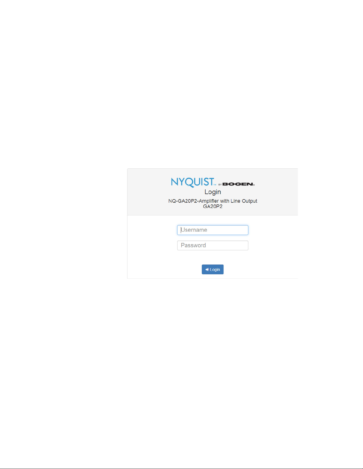
Bogen NYQUIST NQ-GA20P2 Instruction sheet

Nyquist Integrated Power Amplifier
Configuration Manual
NQ-GA20P2
2019 Bogen Communications, Inc.
All rights reserved.
740-00074A
191029


iii
Contents
List of Figures .......................................................................................................v
List of Tables .........................................................................................................vii
Configuring the Nyquist Integrated Power Amplifier.............................................. 1
1 Using the Dashboard...............................................................................3
2 Updating Firmware...................................................................................4
3 Setting Network Tab Parameters........................................................6
4 Setting Configuration Tab Parameters .............................................8
5 Accessing Log Files................................................................................ 11
6 Setting DSP Parameters....................................................................... 15
6.1 Setting the Channel Level................................................... 16
6.2 Muting a Channel .................................................................. 17
6.3 Adjusting Compression Settings...................................... 17
6.4 Setting High Pass/Low Pass Parameters....................... 19
6.5 Adjusting the Limiter ............................................................ 22
6.6 Adjusting Outputs ................................................................. 23
6.7 Adjusting Parametric Equalizer Settings....................... 24
6.8 Settings ...................................................................................... 26
6.9 Signal Present.......................................................................... 27

iv

v
List of Figures
Figure 1, Nyquist Appliance Login . . . . . . . . . . . . . . . . . . . . . . . . . . . 2
Figure 2, NQ-GA20P2 Dashboard . . . . . . . . . . . . . . . . . . . . . . . . . . . . 3
Figure 3, Firmware Update Page . . . . . . . . . . . . . . . . . . . . . . . . . . . . . 5
Figure 4, Network Settings. . . . . . . . . . . . . . . . . . . . . . . . . . . . . . . . . . 7
Figure 5, Appliance Configuration Settings. . . . . . . . . . . . . . . . . . . 10
Figure 6, Logs . . . . . . . . . . . . . . . . . . . . . . . . . . . . . . . . . . . . . . . . . . . . 12
Figure 7, DSP Page with Channel Drop-Down Menu . . . . . . . . . . 15
Figure 8, Compressor Settings. . . . . . . . . . . . . . . . . . . . . . . . . . . . . . 17
Figure 9, High/Low Pass Parameters . . . . . . . . . . . . . . . . . . . . . . . . 19
Figure 10, Limiter Settings . . . . . . . . . . . . . . . . . . . . . . . . . . . . . . . . . 22
Figure 11, Outputs . . . . . . . . . . . . . . . . . . . . . . . . . . . . . . . . . . . . . . . . 23
Figure 12, Parametric Equalizer Settings . . . . . . . . . . . . . . . . . . . . . 24
Figure 13, Settings Parameters . . . . . . . . . . . . . . . . . . . . . . . . . . . . . 26
Figure 14, Signal Present Parameters. . . . . . . . . . . . . . . . . . . . . . . . 27

vi

vii
List of Tables
Table 1, Appliance Dashboard Read-Only Fields . . . . . . . . . . . . . . . 3
Table 2, Appliance Dashboard Buttons . . . . . . . . . . . . . . . . . . . . . . . 4
Table 3, Network Settings . . . . . . . . . . . . . . . . . . . . . . . . . . . . . . . . . . 7
Table 4, Configuration Settings . . . . . . . . . . . . . . . . . . . . . . . . . . . . . 11
Table 5, Logs. . . . . . . . . . . . . . . . . . . . . . . . . . . . . . . . . . . . . . . . . . . . . 13
Table 6, DSP Page . . . . . . . . . . . . . . . . . . . . . . . . . . . . . . . . . . . . . . . . 16
Table 7, Compressor Settings . . . . . . . . . . . . . . . . . . . . . . . . . . . . . . 18
Table 8, High Pass/Low Pass Parameters. . . . . . . . . . . . . . . . . . . . . 20
Table 9, Limiter Settings . . . . . . . . . . . . . . . . . . . . . . . . . . . . . . . . . . . 22
Table 10, Signal Present Parameters. . . . . . . . . . . . . . . . . . . . . . . . . 28

viii

Configuring the
Nyquist Integrated
1
Configuring the Nyquist Integrated
Power Amplifier
The NQ-GA20P2 is a plenum-rated Nyquist 20-watt integrated power
amplifier that works as a page zone extender to facilitate voice access
to a single zone of one-way paging over the Nyquist network.
It also works in background music applications – leveraging the
exhaustive audio management and distribution capabilities of
Bogen’s Nyquist platform.
The NQ-GA20P2 appliance uses the latest in Class D amplifier tech-
nology and provides unparalleled sonic quality, exceptional reliability,
and reduced power consumption to permit standalone PoE+ opera-
tion over the local network.
You can let the Nyquist server or system controller automatically dis-
cover and configure the NG-GA20P2, or you can manually configure
it through the appliance’s web-based user interface (web UI).
A short press of the appliance’s Reset button reboots the device. If
you press the Reset button for 10 seconds, the appliance returns to
the factory default configuration settings. Returning to the default
configuration settings does not change the appliance’s firmware.
The following sections describe the process for manual configuration.
For information about using Nyquist’s automatic configuration pro-
cess, refer to the appropriate Nyquist System Administrator Man-
ual.
Note: Do not use third-party Chrome browser extensions with the
Nyquist user interface.

2
To access the appliance’s UI:
Step 1 Access the appliance’s web UI by doing one of the fol-
lowing:
a On your web browser, enter the IP address for the
appliance as the URL.
b From the Nyquist web UI navigation bar, select Sta-
tions, select Stations Status, navigate to the device
that you want to configure, and then select the Link
icon.
Step 2 At the Nyquist Appliance - Login page, enter username
and password, and then select Login.
Figure 1, Nyquist Appliance Login

3
The dashboard for the selected appliance appears.
1 Using the Dashboard
The dashboard displays the following read-only fields:
Figure 2, NQ-GA20P2 Dashboard
Table 1, Appliance Dashboard Read-Only Fields
Device Type Identifies the physical device used by the
station.
Serial Number Identifies the serial number for the device.
MAC Address Specifies the Media Access Control (MAC)
address, which is a unique identifier
assigned to network interfaces for commu-
nications on the physical network segment.
Firmware Version Provides the firmware version installed on
the station.

4
The dashboard also contains the following buttons:
2UpdatingFirmware
When you select Firmware Update from the appliance’s web UI, the
Firmware Update page appears. From this page you can determine
which Nyquist version the appliance is using and if an update is
Table 2, Appliance Dashboard Buttons
Dashboard Refreshes the dashboard.
Configuration Set-
tings
Accesses the Configuration Settings page
where you can either manually set various
options, such as the SIP Username, or
select to receive configuration settings
from the server.
Network Settings Accesses the Network Settings page where
you can view and set network settings,
such as the static IP address.
Firmware Update Accesses the Firmware Update page where
you can view the current Nyquist version,
check for updates, restore factory settings,
and reboot the appliance.
Logs Accesses log files, which record either
events or messages that occur when soft-
ware runs and are used when trouble-
shooting the appliance.
DSP Accesses the DSP page where you can view
and set parameters for Digital Signal Pro-
cessing (DSP).
Help Accesses the appliance’s online help.
Manual Displays the Nyquist Manual.
Logout Logs out of the appliance’s dashboard.

5
required. You can also use this page to restore factory settings and to
reboot the appliance.
To use the Firmware Update page:
Step 1 On the appliance web UI’s main page, select Firmware
Update to ensure you have the latest firmware version.
Step 2 Select Upload Firmware to upload firmware from the
server to the appliance.
If you select this option, a popup screen appears that
allows you to select the file that you want to upload.
You can navigate to the file’s location. After you select
the file, select Upload. If Nyquist discovers a new firm-
ware version, the Firmware Update page displays an
Update Firmware button. Select this button if you
Note: A Nyquist appliance connected to the Nyquist network receives a config-
uration file from the Nyquist server that includes the latest firmware available
from the server. If the firmware is later than the one installed on the appliance, an
automatic firmware update occurs unless the Firmware parameter for the sta-
tion is left blank. Refer to the Nyquist System Administrator Manual for more
information.
Figure 3, Firmware Update Page

6
want to update the appliance’s firmware to the new
version.
Step 3 If you want to return your appliance to its original state
(undoing firmware updates), select Restore Factory
Settings.
Step 4 Select Reboot Appliance to restart your appliance.
3 Setting Network Tab Parameters
Network settings can be configured dynamically by the Nyquist
server or manually by using the appliance’s web UI.
To manually configure network settings:
Step 1 On the appliance web UI’s main page, select Network
Settings.
Step 2 Select your desired network settings.
Step 3 Select Save.

7
Network settings are described in the following table:
Figure 4, Network Settings
Table 3, Network Settings
Static IP Identifies the fixed IP address assigned
to the appliance by a system administra-
tor.
Netmask Identifies the subnetwork subdivision of
an IP network.
Gateway Identifies the address, or route, for the
default gateway.
VLAN ID Identifies the Virtual Local Area Network
(VLAN) for this appliance. Values range
from 0 to 4094.

8
4 Setting Configuration Tab Parameters
The easiest way to configure Nyquist appliances is to obtain configu-
ration settings from the Nyquist server by selecting Get Configura-
VLAN Priority Identifies the priority of the network traf-
fic on the VLAN. Priority can range from
0 through 7.
NTP Server Identifies the IP address or the domain
name of the Network Time Protocol
(NTP) Server. This field is read only.
TFTP Server Identifies the IP address of the Trivial File
Transfer Protocol (TFTP) server. TFTP is
used by Nyquist VoIP phone and appli-
ance provisioning. A TFTP server runs on
the Nyquist server on port 69 (the stan-
dard TFTP port #).
Device provisioning files are stored on
the Nyquist server in directory: /srv/
tftp. This is the only directory
exposed by the TFTP server.
DHCP Server Over-
ride
Indicates if you want to override the
TFTP server information provided by the
Dynamic Host Configuration Protocol
(DHCP) via option_66.
DHCP supplies IP addresses to the
Nyquist server and associated devices. It
also supplies the TFTP server IP address
or name via option_66.
DHCP Enabled Indicates if the device is enabled to use
DHCP.
Reboot Appliance Allows you to save the network options
and reboot the appliance.
Table 3, Network Settings (Continued)

9
tion From Server. However, you can manually configure an
appliance through the appliance’s Web UI.
To manually configure your Nyquist appliance:
Step 1 On the appliance Web UI’s main page, select Configu-
ration Settings.
Step 2 Select your desired settings.
Step 3 Select Save.
Note: Manual configuration will be overwritten by the server once the appli-
ance is connected and discovered by the server.

10
The following table describes the Configuration tab settings:
Figure 5, Appliance Configuration Settings

11
5 Accessing Log Files
A log file records either events or messages that occur when software
runs and is used when troubleshooting the appliance. From the
appliance’s web-based UI, log files can be viewed directly or exported
Table 4, Configuration Settings
Web Username Provide a web username for this appli-
ance.
Web Password Provide a web password for logging into
the appliance.
Web Confirm Pass-
word
Re-enter the password used to log into
the appliance.
SIP Username Provide the username used for Session
Initiation Protocol (SIP) device registra-
tion.
SIP Password Provide the password used for SIP device
registration.
SIP Confirm Pass-
word
Re-enter the password used for SIP device
registration.
Server Identifies the IP address of the Nyquist
server.
Local Port Identifies the local port.
Emergency-All-Call Identifies the IP address, port number, and
volume used for emergency all-calls
pages.
All-Call Identifies the IP address, port number, and
volume used for all-calls pages.
Audio Distribution Identifies the IP address, port number, and
volume used for audio distribution.

12
via download to your PC, Mac, or Android device and then copied to
removable media or attached to an email to technical support.
To view a log file:
Step 1 On the appliance Web UI’s main page, select Logs.
Step 2 From the drop-down menu, select the log that you
want to view.
Multiple versions of the same log and zipped copies of
the log may be available.
Step 3 To export the file, select Export.
A link to a .txt file appears in the screen’s lower left.
Available logs are described in the following table:
Figure 6, Logs
Other manuals for NYQUIST NQ-GA20P2
2
Table of contents
Other Bogen Amplifier manuals

Bogen
Bogen Flex-Pak CHS-35A User manual

Bogen
Bogen ProMatrix PM-3180 User manual

Bogen
Bogen CT60B User manual

Bogen
Bogen PCM2000 User manual

Bogen
Bogen M-Class M300 User manual

Bogen
Bogen WV250 Guide

Bogen
Bogen CTM User manual

Bogen
Bogen C10 Guide

Bogen
Bogen C10B User manual

Bogen
Bogen NYQUIST NQ-P0100 Instruction sheet