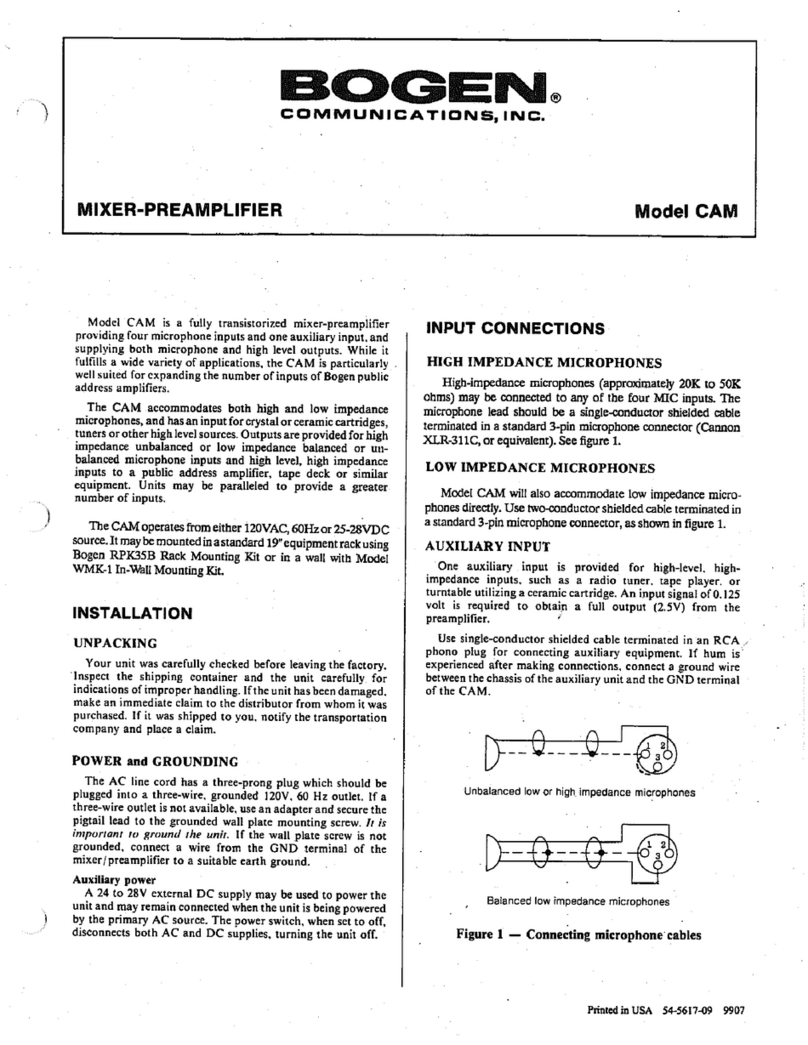
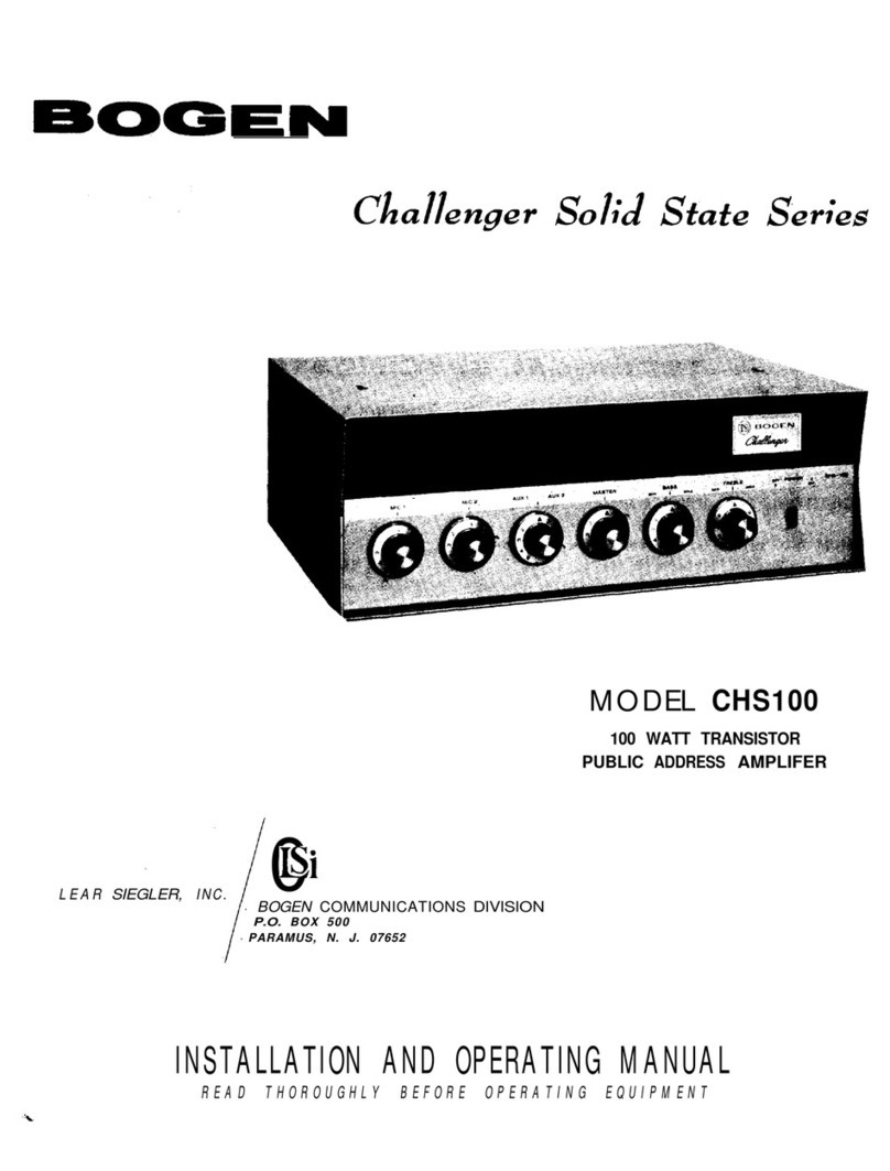
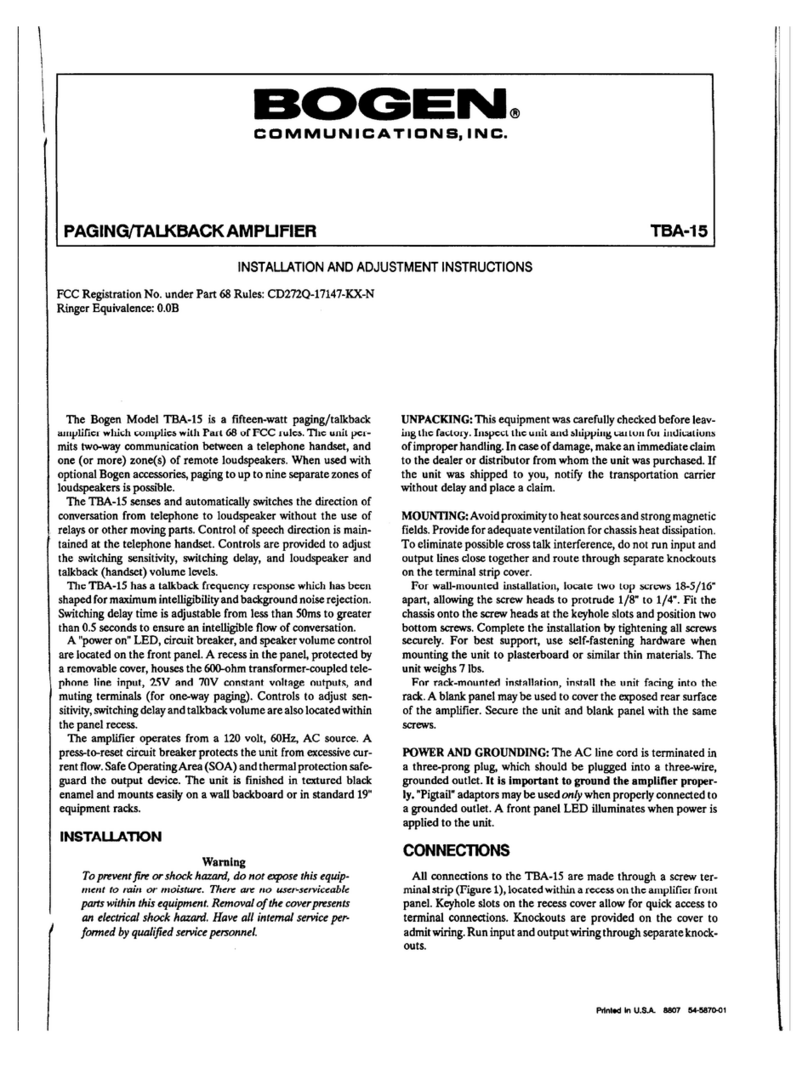
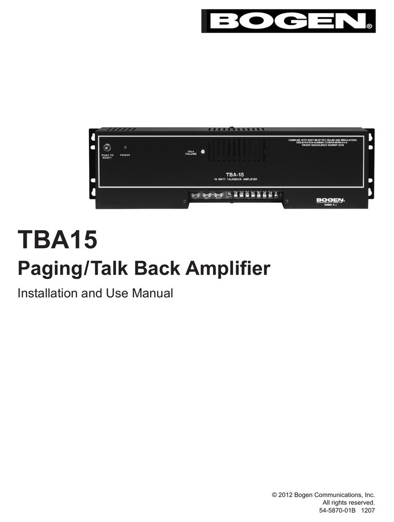
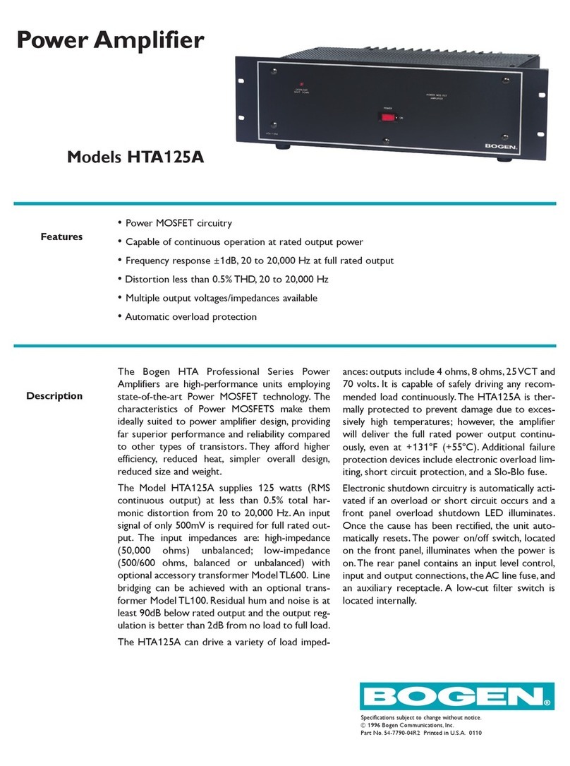
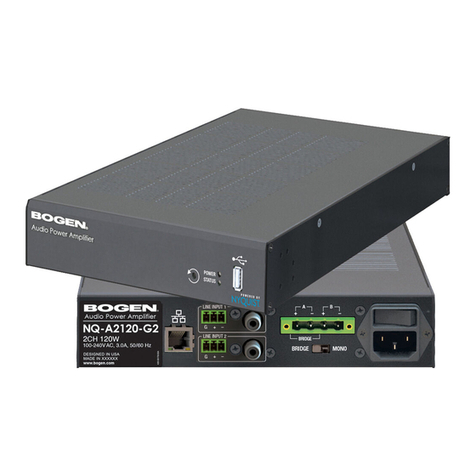
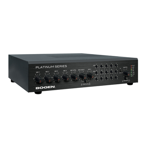
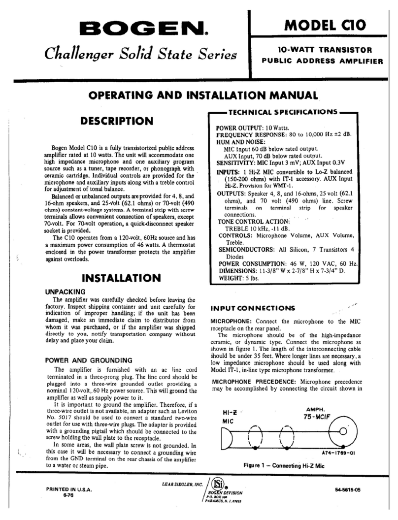
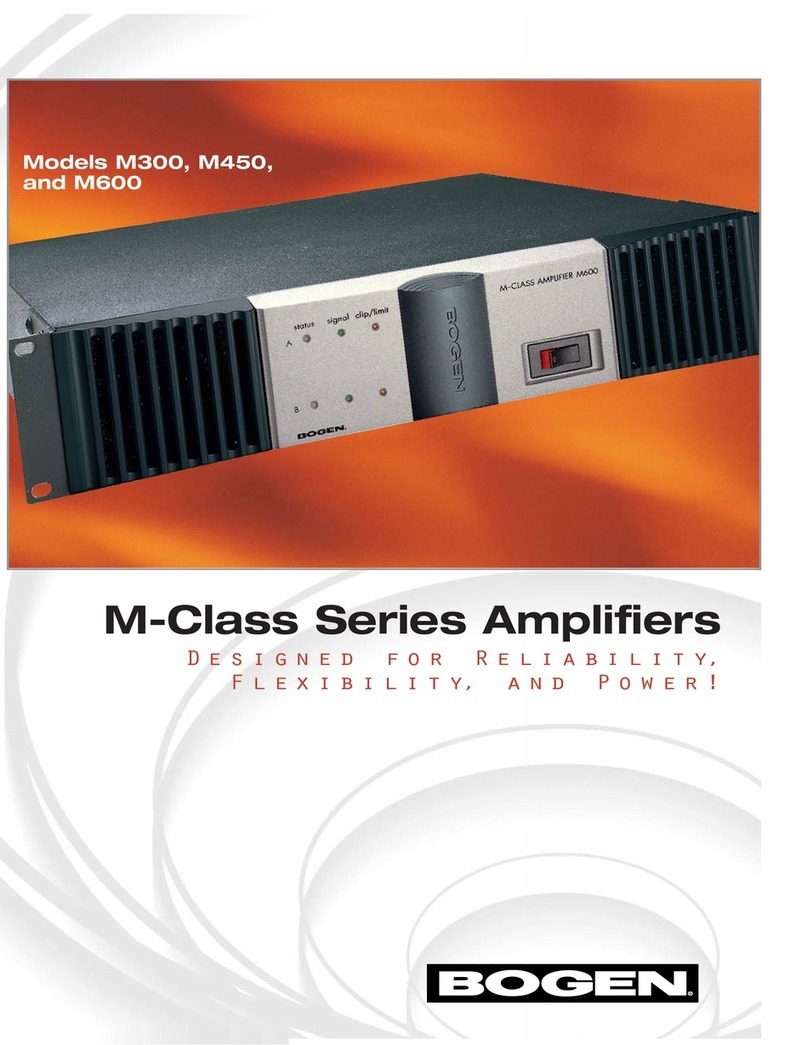
Bogen TPU-15A User manual

BOGEN
COMMUNICATIONS,
INC.
TELEPHONE
PAGING
AMPLIFIER
TPU-15A
CAUTION
Connect
only
to
POX
system
incot
punning
isulutiun
from
telecom
network.
ATTENTION
Raccorder
settlement
u
un
systeme
PBX
indeperuiam
du
reseau
de
telecommunication.
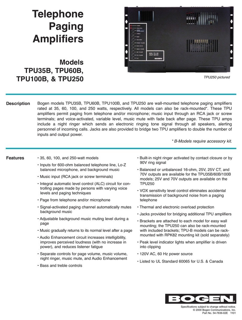
DESCRIPTION
Bogen
Model
TPU-15A
is
a
unique
fifteen-watt,
wall-mounted
amplifier,
specifically
designed
for
telephone
paging
applications.
This
compact
unit
incorporates
state-of-the-art
electronic
technology,
including
voice-activated
muting
of
music
when
paging.
The
page
channel
features
automatic
output
leveling
(ALC)
as
channel
input
varies,
which
is
particularly
advantageous
where
persons
of
varying
voice
levels
and
paging
techniques
have
access
to
the
system.
A
night
ringer
(tone
generator)
is
provided;
a
steady
ringing
tone,
indicating
incoming
calls,
can
be
transmitted
through
the
public
address
system
during
other
than
regular
business
hours.
This
alerts
security
per¬
sonnel
to
answer
the
call.
Input
terminals
are
furnished
for
a
600-ohm
balanced
telephone
line,
a
background
music
source
and
normally-open
dry
contacts
for
the
night
ringer.
Output
terminals
offer
a
choice
of
25
volts,
70
volts,
or
8
ohms
for
connection
of
various
types
of
loudspeakers.
Model
TPU-15A
features
screwdriver-adjustable
controls
for
page,
music,
and
night
ringer
level,
plus
amplifier
tone.
Protective
devices
include
an
LED
overload
indicator
and
a
low-cut
switch
for
use
with
horn
loudspeakers.
The
unit
is
professional
in
styling
and
is
finished
in
black
with
white
lettering.
It
operates
from
a
120VAC,
60Hz
source.
INSTALLATION
CAUTION
The
fallowing
installation
instructions
are
far
use
hy
qualified
service
personnel
only.
To
avoid
an
electric
shock
hazard,
do
not
perform
any
functions
requiring
the
removal
of
the
cover
of
the
amplifier
unless
you
are
qualified
to
do
so.
To
prevent
fire
nr
shock
hazard,
da
not
expose
this
unit
to
rain
or
excessive
moisture.
UNPACKING
Your
unit
was
carefully
checked
before
leaving
the
factory;
inspect
the
shipping
container
and
unit
closely
for
improper
handling.
If
the
unit
has
been
damaged,
make
an
immediate
claim
to
the
distributor
from
whom
it
was
purchased.
If
the
unit
was
shipped
directly
to
you,
save
all
shipping
ma'terial,
notify
the
carrier
immediately
and
place
your
claim.
POWER
AND
GROUNDING
The
AC
line
cord
has
a
three-prong
plug
which
should
be
plugged
into
a
three-wire,
grounded
120V,
60Hz
outlet.
It
is
important
to
ground
the
unit.
If
a
three-wire
outlet
is
not
available,
use
an
adap¬
tor
and
connect
the
grounding
pigtail
to
the
screw
securing
the
wall
plate.
If
the
wall
plate
screw
is
not
grounded,
connect
a
wire
from
the
ground
terminal
of
the
amplifier
to
a
suitable
earth
ground.
MOUNTING
Model
TPU-15A
is
designed
for
surface
wall
mounting.
When
mounting
the
unit,
consider
the
proximity
to
heat
sources
and
power
supply,
adequate
air
flow
for
chassis
heat
dissipation,
and
access
to
controls
and
terminal
wiring,
Where
possible,
secure
to
wall
studs
or
a
suitable
back
brace.
Use
self-fastening
or
molly-type
hardware
on
plasterboard
and
other
thin
materials.
INPUT
CONNECTIONS
PAGING
A
balanced
transformer-isolated
input
for
a
telephone
line
is
pro¬
vided.
One
600-ohm
telephone
line
may
be
connected
at
the
terminals
marked
TIP
and
RING
If
tuo-conductor
shielded
wire
is
used,
con¬
nect
the
shield
to
the
GND
terminal.
MUSIC
An
unbalanced
high-impedance
auxiliary
input
is
provided.
Make
connections
to
terminals
marked
MUSIC
and
GND.
NIGHT
RINGER
A
ringing
tone
can
be
transmitted
through
the
public
address
system
by
connecting
the
NIGHT
RINGER
and
GND
terminals
on
the
TPU
15A
amplifier
through
a
pair
of
normally
open
dry
contacts
(which
are
customer-supplied).
A
steady
ringing
tone
will
be
heard
as
long
as
the
dry
contacts
are
closed.
Printed
in
Korea
8801
54-5876-02

Pated
Power
Output:
Distortion*
Frequency
Response:
Sensitivity*
Inputs:
Outputs:
Signal
to
Noise
(“A”
weighted):
Controls
and
Indicators:
Tone
Control:
Low
Cut:
ALC
(Page
Channel):
Power
Consumption
(120VAC,
60Hz):
TECHNICAL
SPECIFICATIONS
15
watts
RMS
Loss
than
2%
Music—lOWz
to
12kHz
±2dB
Paging
—shaped
for
maximum
intelligibility
Music
—70mV
Paging
-20dBm,
600
ohms
Music—
Hi-Z
AUX,
25k
ohms,
unbalanced
Paging
—600
ohms
balanced,
transformer-isolated
Night
Ringer—
steady
tone
while
dry
contacts*
are
closed
15
watts
@
8
ohms;
25V
and
70V
balanced,
transformer-coupled
-70dB
Screwdriver-adjustable—PAGE
VOLume,
MUSIC
VOLume,
NIGHT
RINGER
VOLume,
and
TONE;
LO-CUT
switch
(for
horn
protection);
PEAK
LEVEL-indicating
LED
(ON
when
peak
output
exceeds
rated
output),
CIRCUIT
BREAKER
-3dB
@
2.5kHz;
6dB
per
octave
-3dB
@
350Hz;
6dB
per
octave
+1,
—3dB
output
level
change
with
15dB
input
level
change
(ref.
—20dBm
rated
input
sensitivity)
.4A,
48W
•Customer-supplied
All
specifications
subject
to
change
without
notice.
OUTPUT
CONNECTIONS
SPEAKERS
The
unit
provides
8-ohm,
25V
and
70V
transformer-coupled
out¬
puts,
balanced
or
unbalanced.
Connect
the
system
speaker
to
the
out¬
put
terminals,
with
one
lead
to
the
COM
terminal
and
the
other
to
the
iciinitial
which
corresponds
to
the
impedance
or
tne
speaker
system.
OPERATION
POWER
Once
connection
has
been
made
to
a
120VAC,
60Hz
power
source,
the
TPU-13A
will
remain
m
a
power
standpy
condition.
(See
CIRCUIT
BREAKER
information,
also.)
CONTROLS
PAGING
The
PAGE
VOLume
screwdriver-adjustable
control
is
used
to
adjust
the
volume
ot
the
page
input.
Rotate
the
control
clockwise
to
increase
volume
and
counterclockwise
to
decrease
it.
Set
the
control
to
minimum
if
the
input
is
not
used.
MUSIC
The
MUSIC
VOLume
screwdriver-adjustable
control
is
used
to
ad¬
just
the
volume
of
the
background
music
input.
Rotate
the
cunliul
clockwise
to
increase
volume
and
counterclockwise
to
decrease
it.
If
the
input
is
not
used,
set
the
control
to
minimum.
NIGHT
RINGER
CONTROL
The
NIGHT
RINGER
VOLume
is
screwdriver-adjustable
through
the
top
of
the
unit.
Rotate.
th<»
rnntml
I'lnrliuicp
to
increase
volume
and
counterclockwise
to
decrease
it.
TONE
CONTROL
The
TONE
screwdriver-adjustable
control
is
used
to
adjust
the
tonal
value
of
the
amplifier
output.
Rotate
the
control
fully
clockwise
to
provide
a
nominal,
flat
high-frequency
response
and
counterclock¬
wise
to
decrease
it.
2

H
5
Z
3
Figure
1—Schematic
Diagram,
Model
TPU-15A

LO-CUT
SWITCH
The
LO-CUT
filter
is
used
to
decrease
low-frequency
response
when
hom-type
paging
speakers
are
used.
Move
the
switch
to
the
nght
(toward
the
marking)
to
enable
this
feature.
PEAK
LEVEL
INDICATOR
A
front-panel
LED
will
illuminate
when
the
amplifier
is
driven
into
clipping.
Adjust
the
output
level
of
the
PAGE,
MUSIC,
and/or
NIGHT
RINGER
if
the
LED
remains
ON.
CIRCUIT
BREAKER
If
the
circuit
breaker
opens,
the
amplifier
output
will
cease.
Discon¬
nect
the
plug
from
the
outlet
and
momentarily
depress
the
red
circuit
breaker
reset
button.
Reapply
power;
if
the
breaker
trips
again,
do
lot
attempt
to
reset
it.
Have
the
unit
checked
by
a
qualified
technician.
MAINTENANCE
CAUTION
There
are
no
user-replaceable
parts
within
the
unit.
To
avoid
an
electric
shock
hazard,
have
all
internal
ser¬
vicing
done
by
a
qualified
technician.
The
warranty
will
become
void
if
repairs
are
made
by
other
than
the
Bogen
Service
Department
or
an
authorized
service
agency.
BOGEN
SERVICE
We
are
interested
in
the
maintenance
of
your
Bogen
equipment.
In
the
event
of
any
difficulty,
do
not
hesitate
to
ask
our
advice
or
assistance.
Information
may
be
obtained
by
writing
to
Service
Depart¬
ment,
Bogen
Communications,
Inc.,
P.O.
Box
575,
Ramsey,
NJ
07446.
When
communicating
with
us,
give
the
model
and
series
designa¬
tion
of
your
unit,
describe
the
difficulty
and
include
details
of
the
electrical
connections
to
associated
equipment.
We
will
send
you
information
if
the
remedy
appears
simple.
If
service
is
required,
we
will
send
you
the
name
and
address
of
the
nearest
authorized
Bogen
Service
Agency.
When
shipping
your
unit,
pack
it
well,
using
the
original
shipping
carton
or
a
similar
container
and
filler
material
to
prevent
damage
in
transit.
Send
the
unit,
fully
insured
and
prepaid,
via
UPS
or
any
responsible
carrier.
It
will
be
promptly
repaired
and
returned
to
you
collect
Cor
prepaid
while
in
warranty).
REPLACING
COMPONENTS
CAUTION
Improper
soldering
may
damage
components
or
the
printed
circuit
hnnrd
Such
dnmnge
c/m
void
the
warranty.
Many
semiconductor
components
are
soldered
in
place
to
ensure
maximum
reliability.
When
soldering
transistors
or
diodes,
use
a
heat
sink
(such
as
a
small
alligator
clip)
between
the
component
and
the
source
of
heat.
Unless
you
are
experienced
in
the
removal
of
IC
com¬
ponents,
do
not
attempt
to
remove
them,
since
excessive
heat
can
damage
an
IC
and/or
the
printed
circuit
board.
If
you
are
certain
that
an
IC
is
defective,
the
easiest
method
of
removal
is
to
cut
the
leads
off
close
to
the
component
and
desolder
the
leads
individually.
If
you
are
not
certain
an
IC
is
defective,
the
use
of
a
low-wattage,
vacuum-
type
desoldering
tool
(such
as
Ungar
Type
7800)
is
advised.
REPLACEMENT
PARTS
Most
components
are
standard
parts
available
through
reputable
parts
suppliers.
The
parts
listed
herein
may
be
obtained
from
the
fac¬
tory.
When
ordering
a
part,
specify
the
part
number
as
listed,
the
model
number
of
the
unit,
and
give
the
series
designation,
which
is
a
letter
followed
by
numbers,
printed
on
the
chassis.
For
parts
on
the
circuit
boards,
also
give
the
component
board
assembly
number,
which
begins
with
“45.”
Schem.
Ref.
fort
No.
Description
Component
Boards
-
45-7288-05
Component
Board
Assembly
(Main
Board)
C2,4,9,11,
17,23
79-126-055
Cap.,
Elect.,
4.7/tF,
50V
CIO
79-126-057
Cap.,
Elect.,
47,tF,
50V
C14
79-126-053
Cap.,
Elect.,
100/tF,
35V
C18
79-119-015
Cap..
Elect..
3300
mF.
63V
C19
79-126-044
Cap.,
Elect.,
IOOO/aF,
35V
CR1
96-5691-01
Diode,
Zener,
4.7V,
IN5230A
CR2,4,5
96-5430-01
Diode,
IN4148
CR3
96-5344-08
Diode.
Zener.
30V
CR6-9
96-5333-01
Diode,
400prv
@
1A
CR10.11
96-5684-02
Diode,
Zener,
2.2V,
IN4680A
CR12
96-5692-01
Suppressor,
Transient,
SCM16C
IC1
96-5690-01
IC,
LM833N
IC2
96-5649-01
IC,
LM1875T
LED1
96-5576-01
LED,
Red
Ql-3
96-5641-01
Transistor,
MPS4123
R1.13
77-001-843
Control.
500
kilohrm.
Audio
R3
77-001-817
Control,
10
kilohms,
Audio
R9
77-007-002
Trimpot,
4700
ohms
R21
76-146-109
Resistor,
1
ohm,
1/4
watt,
5%
SWI
81-003-067
Switch,
Slide
T1
83-060-000
Transformer,
Input
—
45-7351-05
Component
Board
Assembly
(Night
Ringer)
C4
79-126-069
Cap.,
Elect.,
IpF,
50V
IC1
96-5667-01
IC,
f*A78L10
IC2
96-5729-01
IC,
KA2418
R4
77-015-001
Trimpot,
100
ohme
Chassis
CB101
94-0025-03
Circuit
Breaker,
0.63A
T101
83-837-000
Transformer,
Power
T102
83-496-000
Transformer,
Output
BOGEN
50
SPRING
STREET.
P
0.
Bo*
575
RAMSEY.
NJ
07446
(201)
934-8500
Other manuals for TPU-15A
6
Other Bogen Amplifier manuals

Bogen
Bogen Challenger CHB10A User manual

Bogen
Bogen TPU-15A User manual

Bogen
Bogen C10 User manual

Bogen
Bogen TPU-15A User manual

Bogen
Bogen Gold Seal Series Guide

Bogen
Bogen WV100 User manual

Bogen
Bogen C35C User manual

Bogen
Bogen TPU-15A User manual

Bogen
Bogen CC4041 Guide

Bogen
Bogen Wall Mount Modular Amplifier WMA80 User manual
Popular Amplifier manuals by other brands

hivolt
hivolt HAR12S operating manual

Audio Note
Audio Note Mono Block 300b/2A3 instruction manual

Lehmannaudio
Lehmannaudio Silver Cube user manual

Rockford Fosgate
Rockford Fosgate punch 40X2 Operating & installation

Bryston
Bryston SP2 owner's manual

Extron electronics
Extron electronics MPA 401-70V user manual