BOLD T20 User manual

BREATHING BOLD T20
Technical Name: Breather BOLD T20
Trade Name: BreatherBOLD T20
Index
04
CHAPTER 1
NTRODUCTION
CHAPTER 2
GENERAL FEATURES 04
04
04
05
05
05
06
2.1 - GENERAL
2.2 - PHYSICAL CHARACTERISTICS
2.3 - EXTERNAL ELECTRICAL SOURCE
2.4 - INTERNAL ELECTRIC SOURCE
2.5 - ESPECIFICATIONS
2.6 – OUTLET PARAMETERS
2.7 – ALARMS 06

CHAPTER 3
PROTEÇCTION AND SECURITY 06
06
07
07
3.1 - FIO2 READING
3.2 – IP PROTECTION LEVEL
3.3 - FILTERS
3.4 – PORTABILITY 07
07
CHAPTER4
VENTILATION MODES
CHAPTER 5
INDICATORS, CONTROLS AND ALARMS 08
08
5.1 - FRONT PANEL
5.2 - POTENTIOMETERS 08
CHAPTER 6
ASSEMBLY AND OPERATION OF EQUIPMENT 09
09
10
11
12
6.1 - STEP BY STEP
6.2 – ALARM DESCRIPTION
6.3 - LCD FABRIC
6.4 - ELECTRICAL CONNECTION
6.5 - VENTILATOR CHANGABLE ACESSORIES 12
CHAPTER 7
PREVENTIVE MAINTENANCE
14
7.1 - MAINTENANCE PLAN 14
CHAPTER 8
CLEANING AND DISINFECTING 15
15
8.1- CLEANING OF THE REANIMATOR AND ITS PARTS
8.2- DISINFECTING OF THE REANIMATOR AND ITS PARTS 15
CHAPTER 9
WARRANTY 15
Breather BOLD T20

- 4 -
Breathing BOLD T20
Chapter 1
Introduction
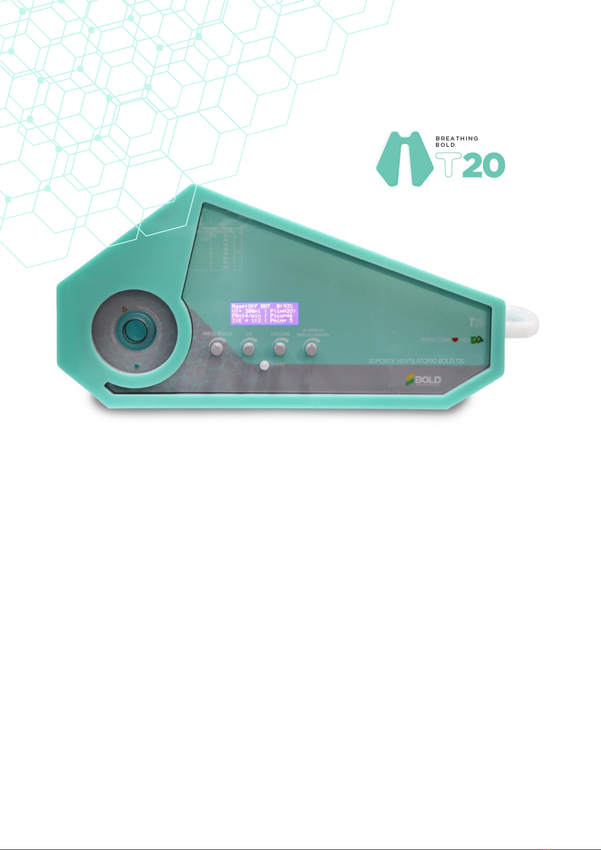
BOLD T20 pulmonary ventilator is a mechanical ventilator with a continuous cycle of a volume control, which can be
defined from the control panel.
The ventilation generator is given through the compression of a reanimator in lieu of an air compressor or pneumatic,
with integrated filter system through HEPA filters ,for non dispersion of particles / bacteria in the environment. The
equipment also has a respiratory frequency variation, which allows it to have a range that goes from bradypnea to
tachypnea.
Inspiratory volume adjustable and easy to read, being able to vary from volumes from 200 ml to 400 ml, according to the
patient's weight, allowing the device to be used in adults and children. In addition, the relationship between inspiration
and expiration can be programmed according to necessity of each case.
Chapter 2
General Features
2.1 - GENERAL
MODEL
BOLD T20
ANVISA REGISTRATION PENDING APPROVAL
MEDICAL PRODUCT CLASSIFICATION CLASS II
OPERATING MODE MANDATORY CONTINUING VENTILATION
CLASSIFICATION ACCORDING TO TYPE AGAINST SHOCK
ELECTRIC (ISOLATION)
CLASS I - INTERNALLY ENERGIZED
EQUIPMENT
PROTECTION DEGREE OF NOCIVE WATER
IP21
2.2 - PHYSICAL CHARACTERISTICS PARAMETERS VALUES
DIMENSIONS
HEIGHT 9.8 in
LENGTH 10.43 in
DEPTH 21.48 in
WEIGHT W/O PACKAGING 26.45 lbs
WEIGHT WITH PACKAGING 28.66 lbs

- 5 -
2.3 - EXTERNAL ELECTRICAL SOURCE
VOLTAGE - INPUT CURRENT
100V –240V
VOLTAGE - OUTPUT CURRENT
19V - 3,42A
FREQUENCY
50 A 60 HZ
POWER
65W
2.4 - FONTE ELÉTRICA INTERNA
NOMINAL VOLTAGE
12 V
NOMINAL CAPACITY
9 AH
AUTONOMY AUTONOMY FULL BATTERY CHARGE
77ºF (25ºC) 5 HOURS OF AUTONOMY
CHARGING TIME WITH BATTERY
FULLY DOWNLOADED 5 HOURS
2.5 - SPECIFICATIONS
VENTILATION MODE MANDATORY CONTINUING VENTILATION -
CONTROLLED AT VOLUME
RELATION I:E
1:1 1:2 E 1:3
VENTILATOR FREQUENCY
10 - 35 IRPM
CURRENT VOLUME
200 A 500 ML
PEEP
2,5 A 20 CMH2O
STAND BY MODE YES
2.6 - OUTLET PARAMETERS
CURRENT VOLUME (IN ML)
PEAK PRESSURE (CMH2O)
RESPIRATORY FREQUENCY (IRPM)
BATTERY STATUS
OPERATION STATUS

- 6 -
Breathing BOLD T20
2.7 - ALARMS
HIGH PRIORITY
BATTERY WITH 2% CHARGE
AVERAGE PRIORITY
BATTERY WITH 15% CHARGE
MINIMUM PRESSURE
MAXIMUM PRESSURE
LOW PRIORITY
MINIMUM PRESSURE
BLACKOUT
BATTERY IN USE
Chapter 3
Security and Protection
3.1 - FIO2 READING
VOLUME (L / MIN) FIO2 (%) -WITH OXYGEN RESERVATORY
0
21
1
40
2
50
3
60
4
70
5
83
6
95
7
100
IT IS NECESSARY THE INSTALATION OF OXYGEN MONITOR BY THE OPERATOR OF THE SERVICE
EQUIPMENT
THE IS A MEDICAL EQUIPMENT THAT MUST BE OPERATED BY QUALIFIED AND
TRAINED PERSONNEL , OVER A DIRECT SUPERVISION OF A MEDICAL DOCTOR.
- 7 -
Breathing BOLD T20
3.2 - IP PROTECTION LEVEL
The BOLD T20 Pulmonary Ventilator consists of IP21 protection, against solid particles with 12.5mm diameter and
drops that fall vertically, in accordance with IEC 60529 regulations - Degrees of protection provided by enclosures (IP
Code).
3.3 - FILTERS
The equipment contains an integrated filtering system, for which the bacterial filtration is carried out through a high
HEPA efficiency. With 99.999999% efficiency against bacteria and 99.9999% against viruses, this filter guarantees no
proliferation of diseases in the environment and cross infections during the treatment of patients.
3.4 - PORTABILITY
Portable equipment, with reinforced structure that guarantees that the equipment operates normally during its
handling and abrupt movements of emergencies.
Chapter 4
Ventilation Modes
Continuous mandatory ventilation controlled at volume , manually controlled by operator through the front panel.
SYNCHRONIZED VENTILATION SYSTEM AND UNUAVAILABLE VENTILATION SUPPORT
NON-INVASIVE VENTILATION SYSTEM UNAVAILABLE.
CONSTANT ATTENTION OF SPECIALIZED PERSONNEL IS REQUIRED WHEN THE PATIENT IS
CONNECTED
WHENEVER THE VENTILATOR IS IN USE, AN ALTERNATIVE VENTILATION MEANS MUST
BE AVAILABLE.
OPERATING PROBLEMS REQUIRE IMMEDIATE CORRECTIVE ACTION
- 8 -
:
Breathing BOLD T20
Chapter 5
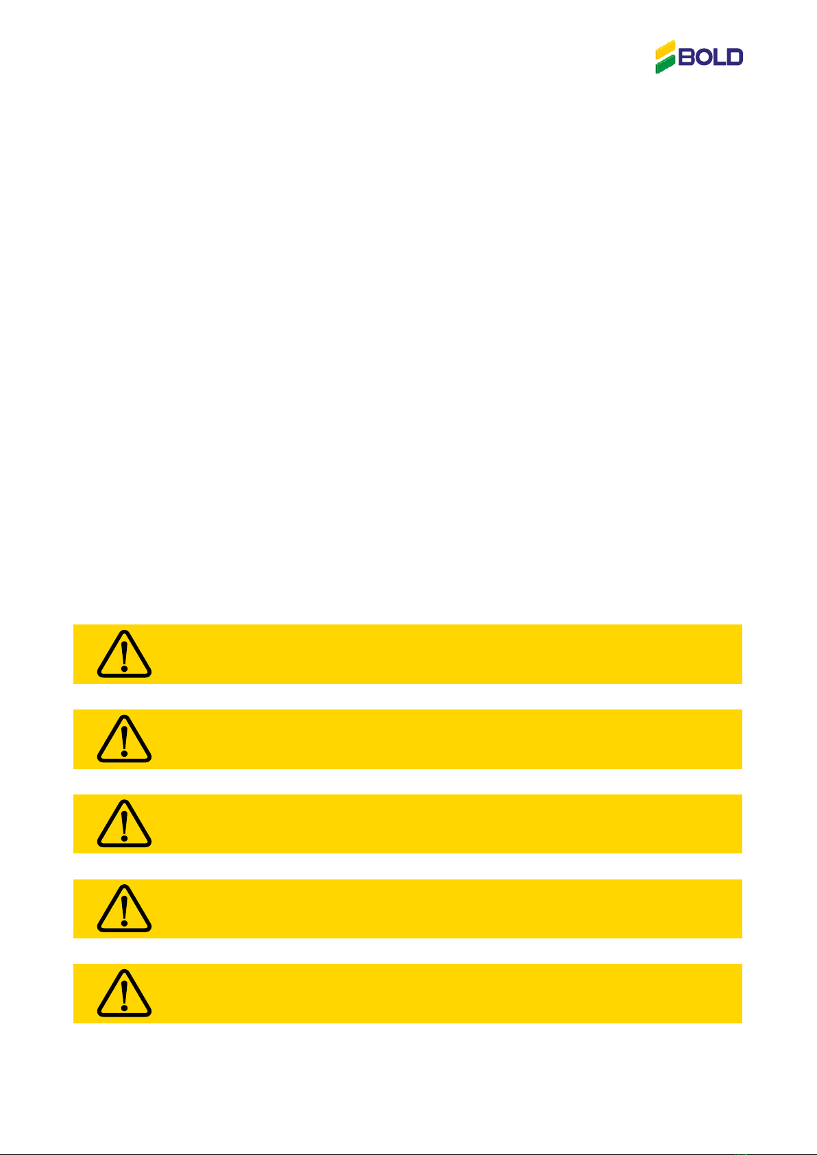
INDICATORS, CONTROLS AND ALARMS
5.1- FRONTAL PANEL
5.2- POTENTIOMETERS
I:E
ALARME DE
PRESSÃO MÁXIMA
Through this potentiometer, the operator is able to select the Inspiration
Relationship and the desired expiration. Whether 1:1, 1:2 or 1:3
Through this potentiometer, the operator is able to select the
current volume wanted : 200 to 400 mL.
Through this potentiometer, the operator is able to select the desired
tidal volume. 200 to 500 mL.
Through this potentiometer, the operator is able to set the maximum alarm pressure.
After selecting the parameters, the operator must press “Start” so that the device can start
operating.

Breathing BOLD T20
Chapter 6
Assembly and Operation of the Equipment
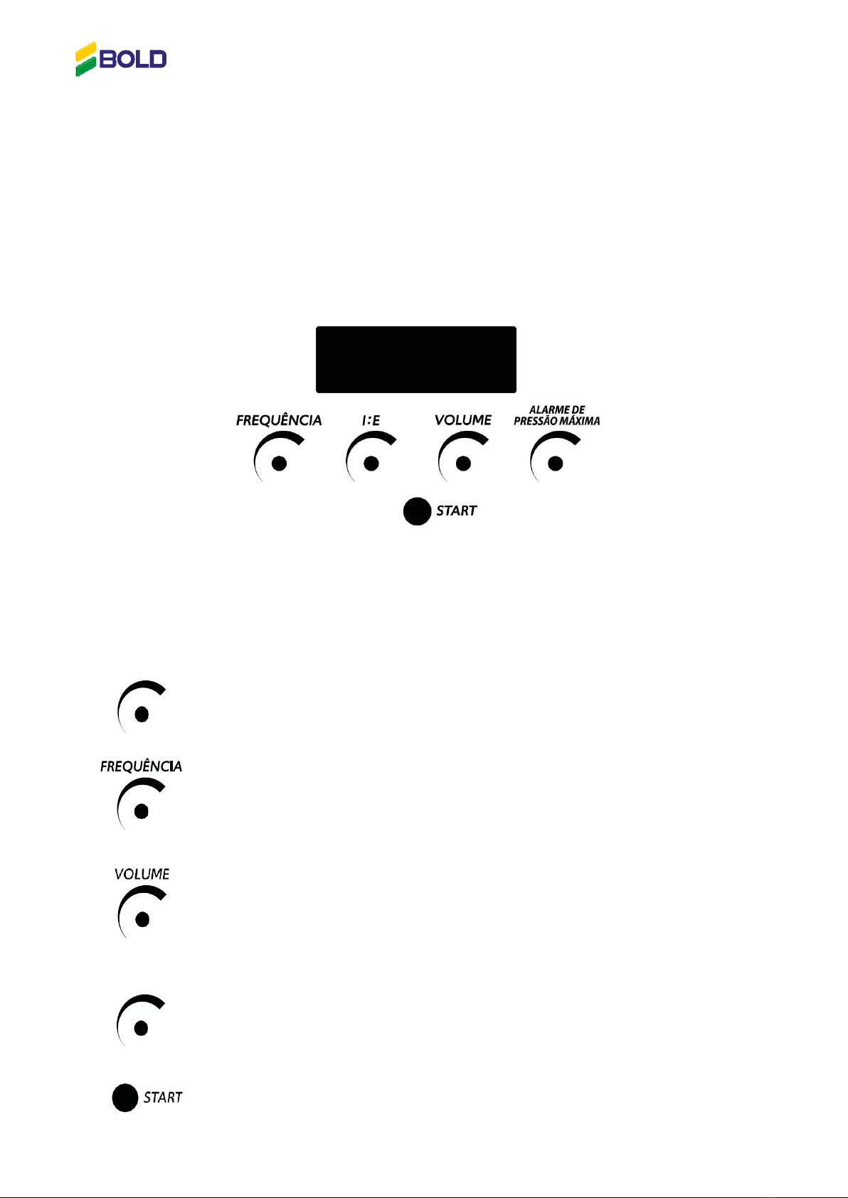
6.1 - STEP BY STEP
Passo 1 - - Unpack the product from the box carefully, in the direction indicated by the sign on the outside of
the equipment packaging.
Passo 2- Check content, each box must contain:
- Respirador BOLD T20 ;
- Self-inflating balloon;
- Inlet Valve for Reservoir;
- Air Inlet Valve;
- Reservoir with Connector;
- Patient Valve with Pop-off;
- PEEP valve;
- PEEP valve adapter;
- HEPA filter;
- 1.5m ( 4.9 feet) trachea;
- Pressure monitoring hose;
- Instruction Manual
Passo 3- Compress the SELF-INFLATABLE BALLOON at both ends.
Passo 4- With the access door to the interior of the fan open, position the
SELF-INFLATABLE BALLOON inside the cabinet centrally in the support holes,
with the oxygen inlet facing the face opposite the Control Panel.
Passo 5- Squeezing the SELF-INFLATABLE BALLOON
with one hand, pull the balloon connections with
the other hand, inside the side cavity of the cabinet
until they are properly positioned.
Passo 6- Connect the humidifier filled with water to the oxygen network in the
amount instructed by the doctor, and connect the hose that will take oxygen to the
equipment.
-10 -
Breathing BOLD T20
Passo 7- Connect the other end of the oxygen hose to the equipment at the indicated location.
Passo 8- For the good performance of the ventilator, the OXYGEN RESERVOIR must be
connected to the corresponding location on the INTAKE VALVE.
Passo 9- Connect the BIVOLT SOURCE that comes with the product to the P4
connection next to the main switch, and take the plug.
Passo 10- With the TRACHE and ADAPTER BUSHING in hand, connect the adapter to one of
the TRACHE inlets.
Passo 11- Connect the PEEP VALVE and PATIENT VALVE assembly directly to the
vacant end of the TRACHE....
Passo 13- Connect the PEEP VALVE and PATIENT VALVE assembly directly to the vacant end of
the TRACHE.
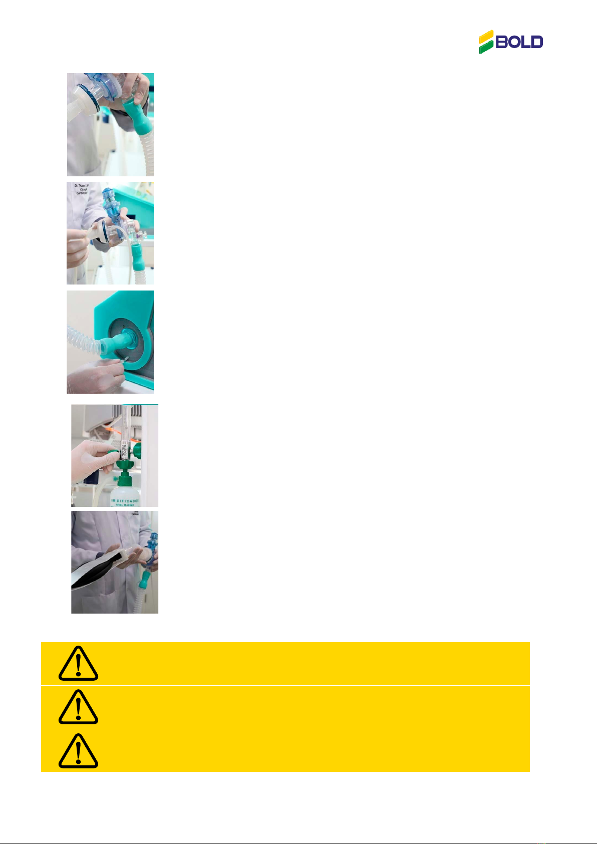
-11 -
Breathing BOLD T20
Passo 14- Connect the HEPA FILTER or HMEF FILTER to the PATIENT VALVE.
Passo 15- With the PRESSURE HOSE that comes with the product, connect one end to
the inlet of the HEPA FILTER or HMEF FILTER..
Passo 16- Take the other end and connect the PRESSURE HOSE to the fan.
Passo 17- With the equipment properly assembled, the oxygen flow
must be opened at 8 L / min and maintain the flow until the OXYGEN
RESERVOIR is fully inflated. Then, flow can be reduced according to the
need for oxygenation.
Passo 18- From this moment on, the BOLD T20 Ventilatory Support
can be activated by the general switch positioned next to the
BIVOLT SOURCE connection on the equipment, and after being
properly parameterized by a health professional, it can be
connected to the patient.
ALL ITS PARTS MUST BE SANITIZED OR STERILIZED, WHEN APPLICABLE,
BEFORE USE.
THE VENTILATION PARAMETERS MUST BE DEFINED BY A DOCTOR AND
ACCORDING TO THE PATIENT'S CONDITIONS.
The QR CODE PRINTED ON THE FAN ALLOWS ACCESS TO THE INSTALLATION VIDEO.

-12 -
Breathing BOLD T20
6.2 - DESCRIPTION OF ALARMS
POWE LOSS
BATTERY WITH 2% CHARGE Upon reaching 2% of the total battery charge, the
equipment stops working and fires
high priority alarms with 2 rounds of 5 pulses with a
5-second interval.
MÉDIA PRIORIDADE
BATTERY WITH 15% CHARGE
Ao
reaches 15% of the total battery charge, the equipment
starts to trigger alarms in 3-pulse salvoes with a 10-
second interval.
MINIMUM PRESSURE Upon reaching a minimum pressure
measurement of less than 5 cmH2O, the
equipment starts to trigger alarms in 3-pulse
salvoes with a 10-second interval. A warning on
the panel is indicated by the [!] Symbol.
MAXIMUM PRESSURE When reaching a maximum pressure
measurement greater than the one set on the
front panel, the equipment starts to trigger
alarms in 3-pulse salvoes with a 10-second
interval. A warning on the panel is indicated by
the [!] Symbol.
LOW PRIORITY
BATTERY IN USE When switching the use of the external source to the
battery, the equipment starts to trigger alarms in 1 pulse
salvoes with an interval of 20 seconds. A panel warning is
signaled by replacing the EXT inscription for BAT.
12 -
-
Breathing BOLD T20
6.2 - DESCRIPTION OF ALARMS
Referências:
Vent - Displays the status of the equipment, being "on" for in service, and "off" for STAND BY;
VT - Tidal volume;
FR - Respiratory Rate;
I: E - Inspiration and Expiration Ratio;
P Peak - Peak pressure;
PEEP - Pressure PEEP
B - Battery charge;
EXT / INT - Power source, being "EXT" for when the equipment is connected to the power network, and "INT"
for when it is being powered by the internal battery.
6.3 - ELECTRICAL CONNECTION
P4 connection, positioned on the back of the equipment.
USE EXCLUSIVELY THE POWER SUPPLY ACCOMPANYING THE PRODUCT.
IN THE EVENT OF A POWER OUTRAGE , THE INTERNAL BATTERY WILL OPERATE
AUTOMATICALLY.

13 -
breathing BOLD T20
6.4 - RESPIRATOR CAMBABLE ACCESSORIES
Adult Reanimator
19V A/C ADAPTOR
12V 9AH BATTERY
-13 -
breathing BOLD T20
PEEP VALVE
PEEP VALVE ADAPTER
OXYGEN RESERVOIR
TRACHEA
HEPA FILTER

-14 -
Chapter 7
Preventive Maintenance
7.1 - MAINTENANCE PLAN
MAINTENANCE USAGE HOURS
1º
1000
2º
2000
3º
3000
4º
4000
5º
5000
1st Maintenance: Battery integrity check, lubrication of wear items, bearing kit and recalibration.
2nd Maintenance: Replacement of the AUTO INFLATABLE BALLOON and general check of the conditions of the other
components.
3nd Maintenance: Verification of the integrity of components drums. It is advisable to replace the battery if the
efficiency presents a significant low, check other parts of the mechanical assembly.
4th Maintenance: Replacement of the AUTO INFLATABLE BALLOON and general check of the mechanical conditions of
the equipment.
5th Maintenance: Check the battery general integrity check of the mechanical conditions of the equipment.
Chap 8
Cleaning and Disinfection
8.1 - CLEANING THE REANIMATOR
In order to correctly clean the reanimator, its parts must be disassembled. The resuscitator must be washed with
warm water and neutral detergent. Rinse withclean distilled water to completely remove the detergent.
8.2 - DISINFECTION OF THE REANIMATOR
It is recommended to disinfect by autoclaving at 121 ° C for 20 min and a pressure of 15 PSI. Single use accessories
should not go through this process.
After cooling, dry the parts completely and reassemble them correctly.

-15 -
breathing BOLD T20
Chapter 9
Warranty
This equipment holds a12 (twelve) months warranty from the date of purchase, with 03 (three) months
corresponding to the legal term and 09 (nine) months the contractual term, where BOLD is responsible for any defect
or failure of The payment of freight is the responsibility of the purchaser for the return of the product.
Installation of the equipment is the responsibility of the purchaser and must be carried out in the exact terms
described in the instruction manual, under penalty of loss of warranty.
The same will occur (loss of warranty), if the use and maintenance of the equipment does not follow the technical
specifications described in the manual, including the periods for preventive maintenance.
THERE WILL BE LOSS OF WARRANTY IN THE EVENT OF BREACH OF WARRANTY SEALS
THERE WILL BE LOSS OF WARRANTY IF THE CABINET SHOWS SIGNS OF FALL, LIKE CRACKS AND
DENTING.

Curitiba - PR
Rodovia BR 116, 11550
Bairro: Prado Velho
Fone: (41) 3378-1268
Curitiba - PR
Diadema - SP
Rua João Corrêa de Sá, 97
Bairro: Vila Nogueira
Fone: (11) 4070-8100
Diadema - SP
Belo Horizonte - MG
Anel Rod. Celso Mello Azevedo, 14718
Bairro: Alto Caiçara
Fone: (31) 3484-7110
Belo Horizonte - MG
Jaraguá do Sul/SC - Unidade Matriz
Rua Manoel Francisco da Costa, 4500
Bairro: João Pessoa
Jaraguá do Sul –SC
CEP: 89257-407
Razão Social: Bold Participações S/A
Inscrição Estadual: 254.265.332
CNPJ:04.626.152/0001-55
+55 47 3274-6500
São José do Rio Preto - SP
Av. Nossa Senhora da Paz,445
Bairro: Jardim Alto Alegre
Fone: (17) 2137-9555
São José do Rio Preto - SP
Bogotá/Colômbia
Autopista Medellín Km 7 Bodega 78-2
Parque Industrial Celta
Fone: +57 1 4322098
Funza –CO
Table of contents
Popular Medical Equipment manuals by other brands


Hang ups Teeter
Hang ups Teeter EP-950 Assembly instructions

Veterinary technics
Veterinary technics 7F-5 user manual

Otto Bock
Otto Bock 4R212 Instructions for use

Teufel
Teufel Stump Socks user manual

Lowenstein Medical
Lowenstein Medical JOYCEeasy Instructions for use

Jones
Jones FlexRx Filling instructions

LINET
LINET LATERA Instructions for use and Technical description

Novanta
Novanta Jadak HS-1RS quick start guide

Sakamoto Model
Sakamoto Model M175 user manual

Otto Bock
Otto Bock 453D2 Instructions for use

ProMed
ProMed Syncro T5 Instructions for installation

McKINLEY
McKINLEY T34 A Guide for Patients & Carers