Hang ups Teeter EP-950 User manual


IMPORTANT SAFETY INSTRUCTIONS
READ ALL INSTRUCTIONS BEFORE USING THE INVERSION TABLE.
WARNING
!
SAVE THESE INSTRUCTIONS
WARNING - To reduce the risk of injury to persons:
• Read and understand all the instructions, view the instructional video, review all other accompanying documents, and inspect the equipment before using the inversion
table. It is your responsibility to familiarize yourself with the proper use of this equipment and the inherent risks of inversion, such as falling on your head or neck,
pinching, entrapment, or equipment failure. It is the responsibility of the owner to ensure that all users of the product are fully informed about the proper use of the
equipment and all safety precautions.
•
Close supervision is necessary when the inversion table is used near children, or by or near invalids or disabled persons.
• Use the inversion table only for its intended use as described in this manual. DO NOT use attachments not recommended by the manufacturer.
• NEVER drop or insert any object into any opening.
• DO NOT use or store product outdoors.
• DO NOT use if you are over 6 ft 6 in (198 cm) or over 300 lbs. (136 kg). Structural failure could occur or head/neck may impact the oor during inversion.
• DO NOT allow children to use this machine.
• Keep children, bystanders, and pets away from machine while in use.
• Keep body parts, hair, loose clothing and jewelry clear of all moving parts.
• The inversion table has no user serviceable parts.
• This product is intended for indoor home use only. DO NOT use in any commercial, rental or institutional setting.
• DO NOT use the equipment without a licensed physician’s approval and a review of the medical contraindications, as noted in the Owner’s Manual.
• Failure to assemble and/or use the equipment as directed may void the manufacturer’s warranty on this product and could result in injury or death.
• Choose a level surface for assembling and operating the table.
• Follow each step in sequence. DO NOT skip ahead.
• Make sure that all fasteners are secure.
• ALWAYS test and inspect the table. Make sure the table rotates smoothly to inverted position and back.
• ALWAYS replace defective components immediately and/or keep the equipment out of use until repair.
FAILURE TO FOLLOW INSTRUCTIONS AND WARNINGS COULD RESULT IN SERIOUS INJURY OR DEATH.
BEFORE YOU BEGIN: Review all steps before beginning assembly and read all precautions before using the inversion table. Carefully adhere to the Assembly
Instructions and Owner’s Manual to help ensure safety and product integrity.
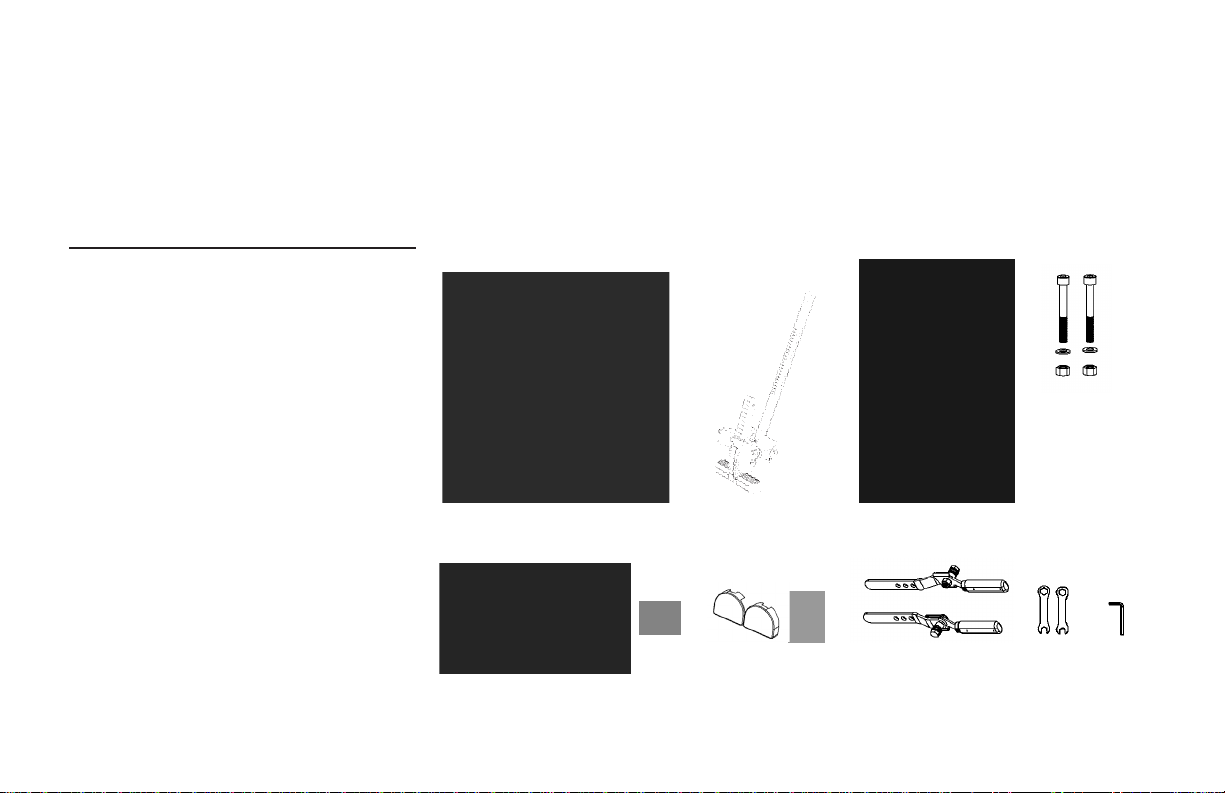
You should have all of the items listed below. If you have any questions on assembly, contact Customer Service at 1-800-847-0143.
A-Frame
EZ-Angle™ Tether Strap
Attached to A-frame
Main Shaft w/Ankle System
Ergo Embrace Cups (4)
Table Bed Assembly
Bolt Set
Bolts
Washers
Nuts
Head Pillow
Over EZ™ Handles
Right Handle
Left Handle
Threaded Bolts (4)
Shrouds
1/4” Bolts
Roller Hinges w/Traction Handles
Wrenches (2)
Allen Wrench (1)
EP-1100
F5-1008
NX-1630
EP-1054
EP-1140
EP-1149
EP-1149-B
EP-1149-D
EP-1149-A
EP-1105
GL-9522
GL-9518
GL-9523
GL-9524
GL-9525
TR-1003
F5-1088
EP-1128-A
ITEMS FOR ASSEMBLY ITEM NUMBER
NX-1630
Items for Assembly
TR-1003 F5-1088
EP-1100
F5-1008
EP-1140
GL-9518
GL-9522 GL-9524 GL-9525
GL-9523 EP-1128-A
EP-1149
EP-1105
Bolts will come pre-assembled in handles and shrouds.

A
B
C
D
E
F
G
H
I
J
K
L
M
N
O
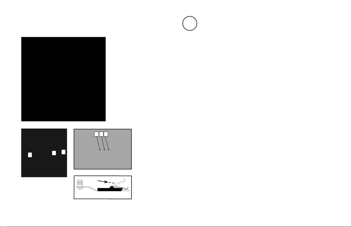
Head Pillow
Table Bed
Over EZ Handles
Traction Handles
Spreader Arms
De-Rattler Knob
Height-Selector Locking Pin
Main Shaft
EZ-Angle Tether Strap
Crossbar
A-Frame
Ankle System
Ergo Embrace Cups
Ankle Comfort Dial
Stability Feet
A
I
M
F
L
J
E
B
G
H
C
D
K
N
O
Before reading further, study the drawing below to familiarize yourself with the important
components of your new Teeter Hang Ups® inversion table.
Before Beginning

Figure 1
Spreader Arms
1Crossbar
2
Assemble the A-Frame Base (EP-1100) and Install the Handles (GL-9518,GL-9522) and Shrouds (GL-9524)
• Open the A-Frame and make sure the Spreader Arms are locked. Rest the A-Frame on the floor (Figure 1).
The Crossbar is at the front.
• Insert two double threaded bolts (GL-9523) through the base of the Left Handle (marked with an “L”) and hand
tighten on the outside with the nuts provided (Figure 2). Line up and insert the opposite end of the bolts through the
corresponding 1/3” holes on the outside of the hinge plate. Loosely tighten with nuts, then use the wrenches
provided to tighten both sets of nuts, being careful not to over tighten. Repeat with Right Handle.
• Place each shroud (GL-9524) over the outside edge of the corresponding handle. Line up and insert the shroud bolts
(GL-9525) through the smaller 1/4” holes in the hinge plate (Figure 2). Use the wrenches provided to tighten the
nuts, being careful not to over tighten.
Step 1
Back
Front
21
Figure 2
Right Left
Bolts will come pre-assembled in handles and shrouds.

1
2
1
Attach the Upper Support Arms to the Table Bed (EP-1140)
• Place the Table Bed face down on the floor and push down on the Support Beam, so the two holes align evenly with
the holes at the base of the Upper Support Arms (Figure 3). You may have to exert extra pressure to ensure that the
Support Beam slides over the rubber spacers.
• Insert the two bolts (EP-1149-B) into the open holes.
• Fasten each bolt with a washer (EP-1149-D) and nut (EP-1149-A).
• Using the Allen Wrench (EP-1128-A) to steady the bolts, tighten the nut onto the bolt with the larger wrench (F5-1088)
(Figure 4). Repeat with the second bolt.
Step 2
Figure 3
Figure 4
2
Support Beam
Upper Support Arms
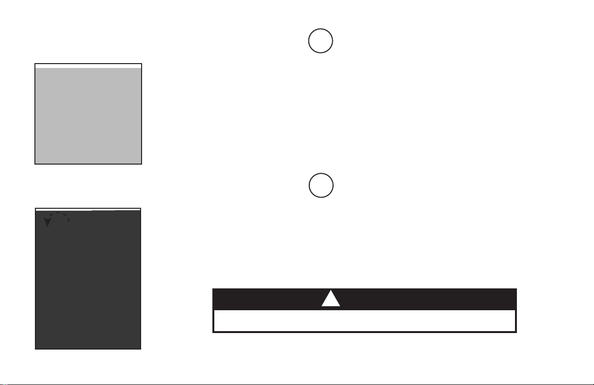
Install the Roller Hinges with Traction Handles (TR-1003) onto the Table Bed (EP-1140)
• For ease-of-assembly, rest the Table Bed against the side of the A-Frame (Figure 5).
• Open the Cam Locks on each side of the Table Bed (Figure 6).
• With the Pivot Pins facing outward, insert the Roller Hinges into the brackets on each side of the Table Bed.
The Roller Hinges must slide between the Cam Locks and the Brackets.
• Engage one of the holes in the Roller Hinge over the bracket pin. Make sure the Roller Hinges are in the same hole
setting on both sides. Figure 7 shows the Roller Hinges engaged correctly in Setting C.
• Push down on the Cam Locks (Figure 8) to secure the hinges.
NOTE: Refer to the Owner’s Manual for an explanation of the hole settings. If you are unsure, use Setting C to start.
Step 3
Figure 5
Figure 6 Figure 7
Figure 8
A B C
2
13
Bracket Pin
2
Cam Lock
3
Pivot Pin
1
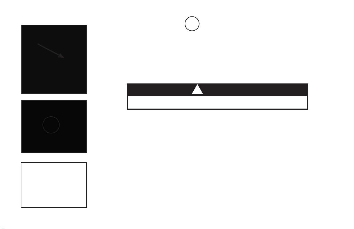
Figure 10
Attach the Table Bed (EP-1140) to the A-Frame (EP-1100)
• Holding each side near the Roller Hinges, pick up the Table Bed and stand at the front of the A-Frame where the
Crossbar is located. Lower each Pivot Pin into the A-Frame hinge plates one at a time (Figure 9). You may need
to push outward on the A-Frame in order to slide the second Pivot Pin into the hinge. Figure 10 shows the correct
placement of the Pivot Pin into the hinge plate.
• Make sure that both Pivot Pins are seated at the base of the slot in the hinge plate. Check to make sure that the
self-locking hooks have closed over both Pivot Pins (Figure 11), and the table rotates smoothly.
Step 4
Figure 9
Figure 11
WARNING
!
Failure of the self-locking hooks to close over both pivot pins is indication of improper
assembly and if not corrected could result in serious injury or death!

Step 5
De-Rattler Knob
Main Shaft Housing
Height-Selector Locking Pin
23
Figure 12
1
2
3
1
Proper Resting
Position
Figure 13
1
1Crossbar
22
Insert the Main Shaft (NX-1630) into the Table Bed (EP-1140)
• Loosen the De-Rattler Knob on the Main Shaft Housing.
• With the height adjustment settings on the Main Shaft facing up, slide the end of the Main Shaft into the Main Shaft
Housing on the Table Bed.
• Pull out the height-selector locking pin to allow the Main Shaft to slide in farther (Figure 12). For the purpose of
easy assembly, slide in the Main Shaft and release the pin in the last height setting (Refer to the Owner’s Manual for
proper height adjustment before use).
NOTE: The De-Rattler Knob is an optional accessory that helps prevent a slight shift in the table when you invert.
The security of the product is not compromised if you choose not to tighten the knob.
• The Main Shaft must rest against the Crossbar of the A-Frame (Figure 13). The Crossbar prevents the table from
rotating forward when the user steps on the Foot Platform. If the Main Shaft does not rest on the Crossbar as
shown in Figure 13 then the Table Bed has been assembled backwards onto the A-Frame and this must be
corrected before use. Step 6
Attach the EZ-Angle Tether Strap (F5-1008) to Limit the Degree of Rotation
• Hook the clip at the end of the tether strap to the loop at the base of the table bed (Figure 14) to limit your degree
of rotation.
• Adjust the EZ-Angle Tether Strap to a comfortable angle of inversion for your experience level:
20° / Twenty Degrees – adjust the strap so the green stripe is in the center of the sliding buckle for inversion to a gentle
twenty-degree angle.
40°/ Forty Degrees – adjust the strap so the orange stripe is in the center of the sliding buckle for inversion to a
moderate forty-degree angle.
60° / Sixty Degrees – adjust the strap so the red stripe is in the center of the sliding buckle for inversion to a more
advanced sixty-degree angle. This is the angle when full decompression is realized.
90° / Ninety Degrees – Remove the tether strap clip from the base of the table bed loop to enable rotation to full inversion.
Figure 14
Step 7
Attach the Head Pillow
• Attach the Head Pillow by securing the Velcro® straps through the holes in the Table Bed - the position of the pillow
can be adjusted depending on the user (Figure 15).
Figure 15
Figure 16
Step 8
Before Use
• Test the table by hand for smooth and steady rotation (Figure 16).
• Ensure that all fasteners are secure.
• Please complete the warranty registration online
• For your reference, the serial number can be found at the base of the Table Bed on the back.
WARNING
!
Read the owner’s manual thoroughly before using your Teeter Hang Ups Inversion Table.
Improper settings could result in serious injury or death!
Adjustments / Maintenance / Storage
Changing the Roller Hinge Setting
• Stand with your legs on either side of the Main Shaft.
• Reach under each Roller Hinge with your index fingers. Use your thumbs to release the locks over the Roller Hinges
(Figure 17).
• Lift both sides of the Table Bed out of the A-Frame at the same time. You may rest the Table Bed on the Crossbar of
the A-Frame.
• Unlock the Cam Locks for each Roller Hinge. Change the Roller Hinges to the desired setting (A, B or C) (Figure 18).
• Re-lock the Cam Locks. Replace the Roller Hinges into the hinge plates of the A-Frame.
Maintenance
• To clean the Table Bed, wipe down with a damp cloth. Do not use abrasive cleaners.
Storing the Inversion Table
• Loosen the De-Rattler Knob.
• Pull the height-selector locking pin and slide the Main Shaft in all the way to the final hole setting. Engage the pin in the
storage setting.
• Rotate the Table Bed opposite from use until it has turned 180 degrees and rests against the Crossbar on the A-Frame.
• Pull up on the Spreader Arms to fold the A-Frame (Figure 19).
NOTE: This operation may pinch fingers if not done slowly and carefully.
Figure 17
Figure 18
Figure 19
A B C
WARNING
!
Tipping Hazard: For upright storage, leave A-frame open wide enough to remain stable, or secure to the wall
to prevent tipping. In households with small children, the table should be stored at on the oor, not upright.
Other manuals for EP-950
1
Table of contents
Other Hang ups Teeter Medical Equipment manuals

Popular Medical Equipment manuals by other brands


Getinge
Getinge Arjohuntleigh Nimbus 3 Professional Instructions for use

Mettler Electronics
Mettler Electronics Sonicator 730 Maintenance manual

Pressalit Care
Pressalit Care R1100 Mounting instruction

Denas MS
Denas MS DENAS-T operating manual

bort medical
bort medical ActiveColor quick guide

AccuVein
AccuVein AV400 user manual


