Bolens BL100, BL150 User manual


RULES FOR SAFE OPERATION
Read the Operator’s Manual and follow all warnings and safety
instructions. Failure to do so can result in serious injury to the
operator and/or bystanders.
FOR QUESTIONS, CALL 1-800-345-8746 IN U.S. OR
1-800-668-1238 in CANADA
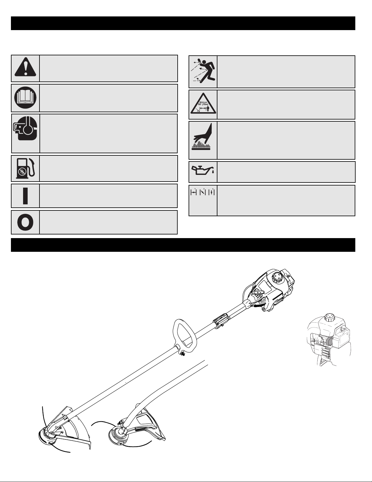
SYMBOL MEANING
WARNING: Failuretoobeyasafetywarningcan
resultininjurytoyourselfandothers.Alwaysfollowthe
safetyprecautionstoreducetheriskoffire,electric
shockandpersonalinjury.
CAUTION: Failuretoobeyasafetywarningmayresult
inpropertydamageorpersonalinjurytoyourselforto
others.Alwaysfollowthesafetyprecautionstoreduce
theriskoffire,electricshockandpersonalinjury.
READ ALL INSTRUCTIONS BEFORE OPERATING
•Readtheinstructionscarefully.Befamiliarwiththecontrolsand
properuseoftheunit.
•Donotoperatethisunitwhentired,illorundertheinfluenceof
alcohol,drugsormedication.
•Childrenundertheageof15mustnotusetheunit;teensmay
operatetheunitwithadultguidance.
•I
nspecttheunitbeforeuse.Replacedamagedparts.Checkforfuel
leaks.Makesureallfastenersareinplaceandsecure.Replacecutting
attachmentpartsthatarecracked,chippedordamagedinanyway.
Makesurethecuttingattachmentisproperlyinstalledandsecurely
fastened.Besurethatthecuttingattachmentshieldisproperlyattached,
andpositionedasrecommended.Failuretodosocanresultinpersonal
injurytotheoperatorandbystanders,aswellasdamagetotheunit.
•U
seonly0.080inch(2.03mm)diameteroriginalequipment
manufacturerreplacementline.Neverusemetal-reinforcedline,wire,
chainorrope.Thesecanbreakoffandbecomedangerousprojectiles.
•Beawareofriskofinjurytothehead,handsandfeet.
•Cleartheareatobecutbeforeeachuse.Removerocks,broken
glass,nails,wire,stringandotherobjectswhichmaybethrown
orbecomeentangledinthecuttingattachment.Cleartheareaof
children,bystandersandpets;keepthemoutsidea50-foot
(15m.)radius,ataminimum.Eventhen,theyarestillatriskfrom
thrownobjects.Encouragebystanderstoweareyeprotection.If
youareapproached,stoptheunitimmediately.
•S
queezethethrottlecontrolandcheckthatitreturnsautomaticallyto
theidleposition.Makealladjustmentsorrepairsbeforeusingtheunit.
•Thisunitwasnotdesignedtobeusedasabrushcutter.Donot
attachoroperatethisunitwithanytypeofbrushcuttingbladeor
brushcuttingattachment.
SAFETY WARNINGS FOR GAS TRIMMERS
•Storefuelonlyincontainersspecificallydesignedandapproved
forthestorageofsuchmaterials.
•Alwaysstoptheengineandallowittocoolbeforefillingthefuel
tank.Neverremovethefueltankcaporaddfuelwhentheengineis
hot.Neveroperatetheunitwithoutthefuelcapsecurelyinplace.
Loosenthefueltankcapslowlytorelieveanypressureinthetank.
•Addfuelinaclean,well-ventilatedoutdoorareawherethereare
nosparksorflames.Removethefuelcapslowly,andonlyafter
theenginestops.Donotsmokewhilefuelingormixingfuel.Wipe
upanyspilledfuelfromtheunitimmediately.
•Avoidcreatingasourceofignitionforspilledfuel.Donotstart
WARNING: Whenusingtheunit,youmustfollowthe
safetyrules.Pleasereadtheseinstructionsbefore
operatingtheunitinordertoensurethesafetyofthe
operatorandanybystanders.Pleasekeepthese
instructionsforlateruse.
• IMPORTANT SAFETY INSTRUCTIONS •
theengineuntilfuelvaporsdissipate.
•Movetheunitatleast30feet(9.1m)fromthefuelingsourceandsite
beforestartingtheengine.Donotsmoke.Keepsparksandopen
flamesawayfromtheareawhileaddingfueloroperatingtheunit.
WHILE OPERATING
•Neverstartorruntheunitinsideaclosedroomorbuilding.
Breathingexhaustfumescanbefatal.Operatethisunitonlyina
well-ventilatedoutdoorarea.
•WearsafetyglassesorgogglesthatmeetANSIZ87.1standardsand
aremarkedassuch.Wearear/hearingprotectionwhenoperating
thisunit.Wearafaceordustmaskiftheoperationisdusty.
•Wearheavylongpants,boots,glovesandalongsleeveshirt.Do
notwearlooseclothing,jewelry,shortpants,sandalsorgo
barefoot.Securehairaboveshoulderlevel.
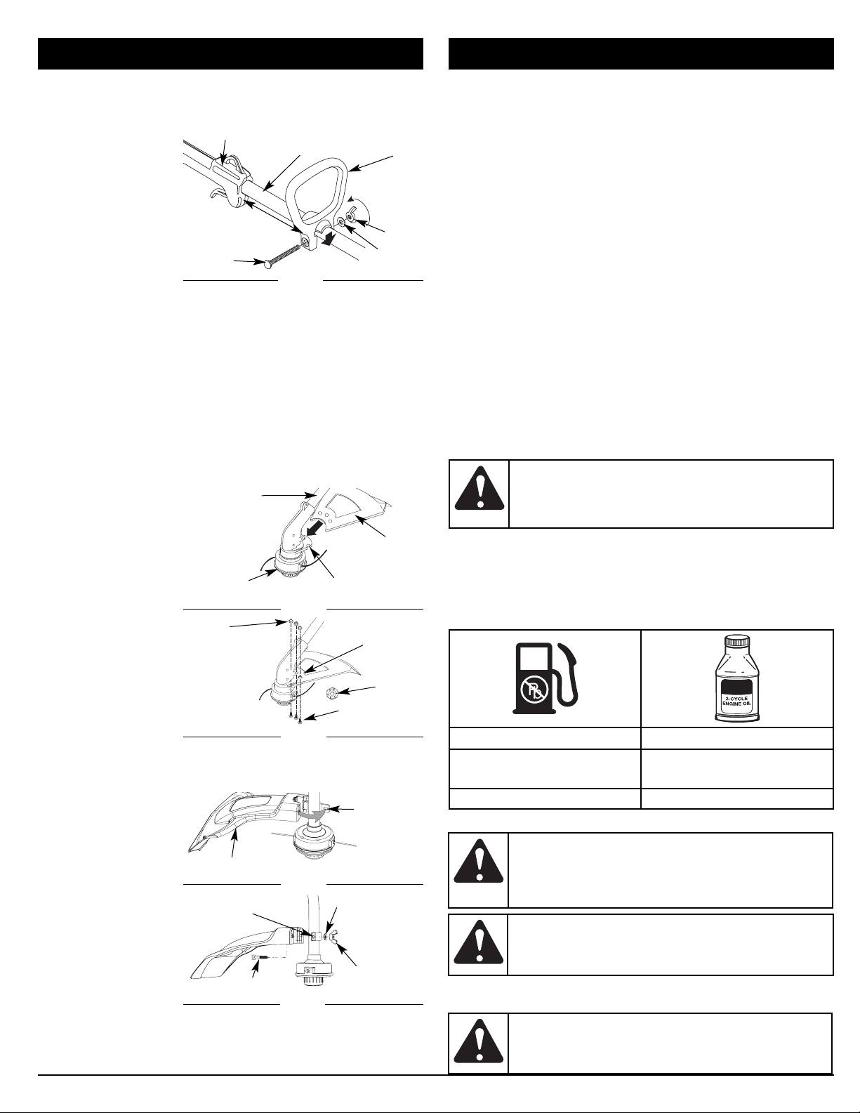
•Thecuttingattachmentshieldmustalwaysbeinplacewhile
operatingtheunit.Donotoperateunitwithoutbothtrimming
linesextended,andtheproperlineinstalled.Donotextendthe
trimminglinebeyondthelengthoftheshield.
•Thisunitdoesnothaveaclutch.Thecuttingattachment
continuesrotatingwhentheengineisidling.Ifitdoesnot,have
theunitadjustedbyanauthorizedservicetechnician.
•AdjusttheD-handletoyoursizeinordertoprovidethebestgrip.
•Besurethecuttingattachmentisnotincontactwithanything
beforestartingtheunit.
•Usetheunitonlyindaylightorgoodartificiallight.
•Avoidaccidentalstarting.Beinthestartingpositionwhenever
pullingthestarterrope.Theoperatorandunitmustbeinastable
positionwhilestarting.RefertoStarting/StoppingInstructions.
•Usetherighttool.Onlyusethistoolforitsintendedpurpose.
•Donotoverreach.Alwayskeepproperfootingandbalance.
•Alwaysholdtheunitwithbothhandswhenoperating.Keepa
firmgriponbothhandlesorgrips.
•Keephands,face,andfeetatadistancefromallmovingparts.Do
nottouchortrytostopthecuttingattachmentwhenitrotates.
•Donottouchtheengine,gearhousingormuffler.Thesepartsget
extremelyhotfromoperation,evenaftertheunitisturnedoff.
•Donotoperatetheenginefasterthanthespeedneededtocut,trim
oredge.Donotruntheengineathighspeedwhennotcutting.
•Alwaysstoptheenginewhencuttingisdelayedorwhenwalking
fromonecuttinglocationtoanother.
•Ifyoustrikeorbecomeentangledwithaforeignobject,stopthe
engineimmediatelyandcheckfordamage.Donotoperate
beforerepairingdamage.Donotoperatetheunitwithlooseor
damagedparts.
•Stoptheunit,switchtheenginetooff,anddisconnectthespark
plugformaintenanceorrepair.
•U
seonlyoriginalequipmentmanufacturerreplacementpartsand
accessoriesforthisunit.Theseareavailablefromyourauthorizedservice
dealer.Useofanyunauthorizedpartsoraccessoriescouldleadto
seriousinjurytotheuser,ordamagetotheunit,andvoidyourwarranty.
•Keepunitcleanofvegetationandothermaterials.Theymay
becomelodgedbetweenthecuttingattachmentandshield.
•Toreducefirehazard,replaceafaultymufflerandsparkarrestor.
Keeptheengineandmufflerfreefromgrass,leaves,excessive
greaseorcarbonbuildup.
OTHER SAFETY WARNINGS
•Neverstoreafueledunitinsideabuildingwherefumesmay
reachanopenflameorspark.
•Allowtheenginetocoolbeforestoringortransporting.Besure
tosecuretheunitwhiletransporting.
•Storetheunitinadryarea,lockeduporuphightoprevent
unauthorizeduseordamage,outofthereachofchildren.
•Neverdouseorsquirttheunitwithwateroranyotherliquid.
Keephandlesdry,cleanandfreefromdebris.Cleanaftereach
use,seeCleaningandStorageinstructions.
•Keeptheseinstructions.Refertothemoftenandusethemto
instructotherusers.Ifyouloansomeonethisunit,alsoloanthem
theseinstructions.
SAVE THESE INSTRUCTIONS
WARNING: Gasolineishighlyflammable,andits
vaporscanexplodeifignited.Takethefollowing
precautions:
2

RULES FOR SAFE OPERATION
Thisoperator'smanualdescribessafetyandinternationalsymbolsandpictographsthatmayappearonthisproduct.Readtheoperator's
manualforcompletesafety,assembly,operatingandmaintenanceandrepairinformation.
• SAFETY ALERT SYMBOL
Indicatesdanger,warningorcaution.Maybeusedin
conjunctionwithothersymbolsorpictographs.
• HOT SURFACE WARNING
Donottouchahotmufflerorcylinder.Youmayget
burned.Thesepartsgetextremelyhotfromoperation.
Whenturnedofftheyremainhotforashorttime.
• WARNING - READ OPERATOR'S MANUAL
R
eadtheoperator’smanual(s)andfollowallwarnings
andsafetyinstructions.Failuretodosocanresultin
seriousinjurytotheoperatorand/orbystanders.
• WEAR EYE AND HEARING PROTECTION
WARNING: Thrownobjectsandloudnoisecan
causesevereeyeinjuryandhearingloss.Weareye
protectionmeetingANSIZ87.1-1989standardsand
earprotectionwhenoperatingthisunit.Useafullface
shieldwhenneeded.
• KEEP BYSTANDERS AWAY
WARNING: Keepallbystanders,especiallychildren
andpets,atleast50feet(15m.)fromtheoperatingarea.
• THROWN OBJECTS AND ROTATING CUTTER CAN
CAUSE SEVERE INJURY
WARNING: Smallobjectscanbepropelledathigh
speed,causinginjury.Keepawayfromtherotatingrotor.
SYMBOL MEANING
SYMBOL MEANING
• CHOKE CONTROL
1.•FULLchokeposition
2.•PARTIALchokeposition
3.•RUNchokeposition
• UNLEADED FUEL
Alwaysuseclean,freshunleadedfuel • OIL
Refertooperator’smanualforthepropertypeofoil.
• ON/OFF STOP CONTROL
ON/START/RUN
• ON/OFF STOP CONTROL
OFForSTOP
KNOW YOUR UNIT
APPLICATIONS
Asatrimmer:
•Cuttinggrassandlightweeds
•Edging
•Decorativetrimmingaroundtrees,
fences,etc.

INSTALL AND ADJUST THE D-HANDLE
1. P
ushtheD-handledownontotheshafthousingsothatthehandle
slantstowardstheshaftgrip(Fig.1).Thesquaredboltholeinthe
handleistotheright.
2. Inserttheshoulder
boltintothesquared
holeinthehandle
andpushthrough.On
theleftsideofthe
handle,placethe
washeronthebolt,
thenscrewthewing
nutontothebolt.Do
nottightenuntilyou
makethehandle
adjustment.
3. R
otatetheD-handletoplacethegripabovethetopoftheshaft
housing.Placeitaminimumof6inches(15.24cm)fromtheendof
theshaftgrip.
4. Whileholdingtheunitintheoperatingposition(Fig.9),position
theD-handletothelocationthatprovidesyouthebestgrip.
5. TightenthewingnutuntiltheD-handleissecure.
INSTALLING THE CUTTING SHIELD
Usethefollowinginstructionsifthecuttingattachmentshieldon
yourunitisnotinstalledorifyoueverneedtore-installit.
Install on a Straight Shaft (BL150)
1. Slidethecuttingattachmentshieldintotheshieldmountonthe
cuttingattachment.Alignthescrewholesintheshieldwiththe
holesinthecuttingattachmentshieldmount(Fig.2).
2. Placeoneofthe
three(3)supplied
hexlocknutsinto
oneofthethree
recessedholeson
thetopofthe
cuttingattachment
shield(Fig3).
3. I
nstallascrewintothe
holefromthebottom
ofthecutting
attachmentshield.
Screwitintothenut
installedinstep2until
itisstarted(Fig3).Do
nottighten.
4. R
epeatsteps2and3
untilallthreescrews
havebeenstarted.
ThentightenallscrewssecurelywithaPhillipsheadscrewdriver.
Install on a Curved Shaft (BL100)
1.
Placethecuttingattachmentshieldontotheshafthousing.Besure
theguardmounting
bracketslidesintothe
slotontheedgeofthe
cuttingshield.Rotate
theshieldintoplace,
counterclockwise(Fig.
4).Theholesinthe
guardmounting
bracketandcutting
attachmentshieldwill
lineup.
2. Frominsidethe
cuttingattachment
shield,pushthe
squareboltthrough
theholeuntilthe
threadedend
protrudesthroughtheguardmountingbracket(Fig.5).
3. Putthewasheronthebolt,thenscrewthewingnutontothe
boltandtighten.
ASSEMBLY INSTRUCTIONS
Shaft Housing
Shield
Mount
Cutting
Attachment
Shield
Cutting
Attachment
Fig. 2
Recessed
Holes
Hex Lock
Nut
Screws (3)
Fig. 3
Nuts (3)
Guard
Mounting
Bracket
Cutting Attachment Shield
Fig. 4
Fig. 5
Square Bolt
Guard
Mounting
Bracket
Wing Nut
Washer
OIL AND FUEL INFORMATION
OIL AND FUEL MIXING INSTRUCTIONS
Oldand/orimproperlymixedfuelarethemainreasonsfortheunit
notrunningproperly.Besuretousefresh,cleanunleadedfuel.
Followtheinstructionscarefullyfortheproperfuel/oilmixture.
DEFINITION OF BLENDED FUELS
Today'sfuelsareoftenablendofgasolineandoxygenatessuch
asethanol,methanol,orMTBE(ether).Alcohol-blendedfuel
absorbswater.Aslittleas1%waterinthefuelcanmakefueland
oilseparate.Itformsacidswhenstored.Whenusingalcohol-
blendedfuel,usefreshfuel(lessthan60daysold).
USING BLENDED FUELS
Ifyouchoosetouseablendedfuel,oritsuseisunavoidable,
followrecommendedprecautions:
•Alwaysusethefreshfuelmixexplainedinyouroperator's
manual
•Alwaysagitatethefuelmixbeforefuelingtheunit
•Drainthetankandruntheenginedrybeforestoringtheunit
USING FUEL ADDITIVES
Thebottleof2-cycleoilthatcamewithyourunitcontainsafueladditive
whichwillhelpinhibitcorrosionandminimizetheformationofgum
deposits.Itisrecommendedthatyouuseour2-cycleoilwiththisunit.
Ifunavailable,useagood2-cycleoildesignedforair-cooledenginesalong
withafueladditive,suchasSTA-BIL®GasStabilizeroranequivalent.Add
0.8oz.(23ml.)offueladditivepergallonoffuelaccordingtothe
instructionsonthecontainer.NEVERaddfueladditivesdirectlytothe
unit'sfueltank.
Thoroughlymixtheproperratioof2-cycleengineoilwithunleaded
gasolineinaseparatefuelcan.Usea40:1fuel/oilratio.Donotmix
themdirectlyintheenginefueltank.Seethetablebelowfor
specificgasandoilmixingratios.
NOTE: Onegallon(3.8liters)ofunleadedgasolinemixedwithone
3.2oz.(95ml.)bottleof2-cycleoilmakesa40:1fuel/oil
ratio.
NOTE: Disposeoftheoldfuel/oilmixinaccordancetoFederal,
StateandLocalregulations.
MIXING RATIO - 40:1
UNLEADED GAS 2 CYCLE OIL
1 GALLON US
(3.8 LITERS) 3.2 FL. OZ.
(95 ml)
1 LITER 25 ml
CAUTION: Forproperengineoperationandmaximum
reliability,paystrictattentiontotheoilandfuelmixing
instructionsonthe2-cycleoilcontainer.Usingimproperly
mixedfuelcanseverelydamagetheengine.
WARNING: G
asolineisextremelyflammable.Ignited
vaporsmayexplode.Alwaysstoptheengineandallowitto
coolbeforefillingthefueltank.Donotsmokewhilefillingthe
tank.Keepsparksandopenflamesatadistancefromthe
area.
WARNING: Removefuelcapslowlytoavoidinjury
fromfuelspray.Neveroperatetheunitwithoutthefuel
capsecurelyinplace.
WARNING: Addfuelinaclean,wellventilated
outdoorarea.Wipeupanyspilledfuelimmediately.
Avoidcreatingasourceofignitionforspiltfuel.Donot
starttheengineuntilfuelvaporsdissipate.
Fig. 1
Bolt Washer
Wing
Nut
Tighten
Shaft Grip
D-Handle
Minimum 6 inches
(15.24 cm)
Shaft Housing
4

STARTING/STOPPING INSTRUCTIONS
WARNING: Removefuelcapslowlytoavoidinjury
fromfuelspray.Neveroperatetheunitwithoutthefuel
capsecurelyinplace.
WARNING: A
voidaccidentalstarting.Makesureyouare
inthestartingpositionwhenpullingthestarterrope(Fig.8).
Toavoidseriousinjury,theoperatorandunitmustbe
inastablepositionwhilestarting.
STARTING INSTRUCTIONS
1. Mixgaswithoil.Fillfueltankwithfuel/oilmixture.SeeOil
and Fuel Mixing Instructions.
2.
MakesuretheOn/OffStopControlintheON(I)position(Fig.6).
3. Fullypressandreleasetheprimerbulb10times,slowly.
Someamountoffuelshouldbevisibleintheprimerbulb
andfuellines(Fig.7).Ifyoucan’tseefuelinthebulb,
pressandreleasethebulbasmanytimesasittakes
beforeyoucanseefuelinit.
4. PlacethebluechokeleverinPosition 1 (Fig.7).
5. Crouchinthestartingposition(Fig.8)andsqueezethe
throttlecontrol.Pullthestarterropebriskly5times.
NOTE: TheunitusesEZ-PullVersion3™,whichsignificantly
reducestheeffortrequiredtostarttheengine.
6. PlacethebluechokeleverinPosition 2.
7. Whilesqueezingthethrottlecontrol,pullthestarterrope
brisklyuntiltheenginestarts.
8. Keepthethrottlesqueezedandallowtheenginetowarm
upfor15to30seconds.
NOTE: Enginemaytakelongertowarmupandreach
maximumoperatingspeedatcoldertemperatures.
NOTE: Unitisproperlywarmedupwhenengineaccelerates
withouthesitation.
9. Oncetheengineiswarmedup,placethebluechokelever
inPosition 3 (Fig.7).Theunitisreadyforuse.
IF... Theenginehesitates,returnchokelevertoPosition2(Fig.7)
andcontinuewarmup.
IF... Theenginedoesnotstart,gobacktostep3.
IF...
Theenginefailstostartafterafewattempts,placetheblue
chokeleverinPosition3andsqueezethethrottlecontrol.Pullthe
starterropebriskly3to8times.Theengineshouldstart.Ifnot,repeat.
IF WARM... Iftheengineisalreadywarm,makesuretheOn/OffStop
controlisintheONpositionandstarttheunitwiththebluechoke
leverinPosition2.Aftertheunitstarts,movethebluechokelever
toPosition3.
STOPPING INSTRUCTIONS
1. Releaseyourhandfromthethrottlecontrol.Allowtheengineto
cooldownbyidling.
2. PressandholdOn/OffStopControlintheOFF(O)position
untilenginecomestoacompletestop.
Fig. 6

OPERATING INSTRUCTIONS
TIPS FOR BEST TRIMMING RESULTS
•Keepthecuttingattachmentparalleltotheground.
•Donotforcethecuttingattachment.Allowthetipofthelinetodo
thecutting,especiallyalongwalls.Cuttingwithmorethanthetip
willreducecuttingefficiencyandmayoverloadtheengine.
•Cutgrassover8inches(200mm)byworkingfromtoptobottom
insmallincrementstoavoidprematurelinewearorenginedrag.
•Cutfromrighttoleftwheneverpossible.Cuttingtotheleft
improvestheunit'scuttingefficiency.Clippingsarethrownaway
fromtheoperator.
•Slowlymovethetrimmerintoandoutofthecuttingareaatthe
desiredheight.Moveeitherinaforward-backwardorside-to-side
motion.Cuttingshorterlengthsproducesthebestresults.
•Trimonlywhengrassandweedsaredry.
•Thelifeofyourcuttinglineisdependentupon;
MAINTENANCE AND REPAIR INSTRUCTIONS
MAINTENANCE SCHEDULE
Performtheserequiredmaintenanceproceduresatthefrequency
statedinthetable.Theseproceduresshouldalsobeapartofany
seasonaltune-up.
NOTE: Somemaintenanceproceduresmayrequirespecialtools
orskills.Ifyouareunsureabouttheseprocedurestake
yourunittoanynon-roadenginerepairestablishment,
individualorauthorizedservicedealer.
NOTE: Maintenance,replacement,orrepairoftheemissioncontrol
devicesandsystemmaybeperformedbyanynon-road
enginerepairestablishment,individualorauthorizedservice
dealer.
Inordertoassurepeakperformanceofyourengine,inspectionofthe
engineexhaustportmaybenecessaryafter50hoursofoperation.If
younoticelostRPM,poorperformanceorgenerallackofacceleration,
thisservicemayberequired.Ifyoufeelyourengineisinneedofthis
inspection,referservicetoanynon-roadenginerepairestablishment,
individualorauthorizedservicedealerforrepair.DONOTattemptto
performthisprocessyourselfasenginedamagemayresultfrom
contaminantsinvolvedinthecleaningprocessfortheport.
WARNING: Topreventseriousinjury,neverperform
maintenanceorrepairswithunitrunning.Alwaysservice
andrepairacoolunit.Disconnectthesparkplugwireto
ensurethattheunitcannotstart.
•Adherenceofthelistedtrimmingtechniques
•Whatvegetationiscut
•Wherevegetationiscut
Forexample,thelinewillwearfasterwhentrimmingagainsta
foundationwallasopposedtotrimmingaroundatree.
DECORATIVE TRIMMING
Decorativetrimmingis
accomplishedby
removingallvegetation
aroundtrees,posts,
fences,etc.
Rotatethewholeunitso
thatthecuttingattachment
isata30°angletothe
ground(Fig.11).
Fig. 11
BL100
BL150
FREQUENCY MAINTENANCE REQUIRED SEE
Beforestartingengine Fillfueltankwithfreshfuel p.4
Every10hours Cleanandre-oilairfilter p.7
Every25hours Checkandcleansparkarrestor
Checksparkplugconditionandgap p.8
p.8
Every50hours Inspectexhaustportandsparkarrestorscreenforcloggingorobstructiontoassuremaximum
performancelevels. p.8
LINE INSTALLATION
ThissectioncoversbothSplitLine™andstandardsingleline
installation.
Alwaysuseoriginalequipmentmanufacturer0.080in.(2.03mm)
replacementline.Lineotherthanthespecifiedmaymakethe
engineoverheatorfail.
Therearetwomethodstoreplacethetrimmingline:
•Windtheinnerreelwithnewline
•Installaprewoundinnerreel
Winding the Existing Inner Reel
1. Holdtheouterspool
withonehandand
unscrewtheBump
Knob™
counterclockwise
(Fig.12).Inspectthe
boltinsidethe
BumpKnobto
makesureitmoves
freely.ReplacetheBumpKnobifdamaged.
2. Removetheinnerreelfromtheouterspool(Fig.13).
3. R
emovespringfromtheinnerreel(Fig.13).
4. Useacleanclothtocleanthetheinnerreel,spring,shaft,and
WARNING: N
everusemetal-reinforcedline,wire,chain
orrope.Thesecanbreakoffandbecomedangerous
projectiles.
Fig. 12

MAINTENANCE AND REPAIR INSTRUCTIONS
GoToStep8forSplitLine™ Installation
6. Takeapproximately
20feet(6m)ofnew
trimmingline,loopit
intotwoequal
lengths.Inserteach
endoftheline
throughoneofthe
twoholesinthe
innerreel(Fig.16).
Pullthelinethrough
theinnerreelsothat
theloopisassmall
aspossible.
7. Windthelinesin
tightevenlayers,
ontothereel(Fig.
17).Windthelinein
thedirection
indicatedonthe
innerreel.Placeyourindexfingerbetweenthetwolinesto
stopthelinesfromoverlapping.Donotoverlaptheendsofthe
line.Proceedtostep11.
SplitLine™ Installation
8. Takeapproximately10feet(3m)ofnewtrimmingline.Insert
oneendoftheline
throughoneofthe
twoholesinthe
innerreel(Fig.18).
Pullthelinethrough
theinnerreeluntil
onlyabout4inches
isleftout.
9. Inserttheendofthe
lineintotheopenholeintheinnerreelandpullthelinetightto
maketheloopassmallaspossible(Fig.18).
10.Beforewinding,splitthelinebackabout6inches.
11.Windthelineintightevenlayersinthedirectionindicatedonthe
innerreel.
NOTE: Failuretowindthelineinthedirectionindicatedwillcause
thecuttingattachmenttooperateincorrectly.
12.
Inserttheendsofthe
lineintothetwo
holdingslots(Fig.19).
13.
Inserttheendsofthe
linethroughtheeyelets
intheouterspooland
placeinnerreelwith
springinsidetheouter
spool(Fig.20).Push
theinnerreelandouter
spooltogether.While
holdingtheinnerreel
andouterspool,grasp
theendsandpullfirmly
toreleasethelinefrom
theholdingslotsinthe
reel.
NOTE: Thespringmust
beassembledon
theinnerreelbeforereassemblingthecuttingattachment.
14.Holdtheinnerreelinplaceandinstallthebumpknobby
turningclockwise.Tightensecurely.
INSTALLING A PREWOUND REEL
1. Holdtheouterspoolwithonehandandunscrewthebump
knobcounterclockwise(Fig.12).Inspecttheboltinsidethe
bumpknobtomakesureitmovesfreely.Replacethebump
knobifdamaged.
2. Removetheoldinnerreelfromtheouterspool(Fig.13).
3. Removethespringfromtheoldinnerreel(Fig.13).
4. Placethespringinthenewinnerreel.
Fig. 16
Loop
NOTE: Thespringmustbeassembledontheinnerreelbefore
reassemblingthecuttingattachment.
5.
Inserttheendsofthelinethroughtheeyeletsintheouterspool(Fig.20).
6. Placethenewinnerreelinsidetheouterspool.Pushtheinner
reelandouterspooltogether.Whileholdingtheinnerreeland
outerspool,grasptheendsandpullfirmlytoreleasetheline
fromtheholdingslotsinthespool.
7. Holdtheinnerreelinplaceandinstallthebumpknobby
turningclockwise.Tightensecurely.
AIR FILTER MAINTENANCE
Removing the Air Filter/Muffler Cover
1. PlacethebluechokeleverinPosition2(Fig.21).
NOTE: Thebluechoke
levermustbein
Position2to
removetheair
filter/muffler
cover.
2. Removethefour(4)
screwssecuringthe
airfilter/muffler
cover(Fig.21).Use
aT-20Torxbit
screwdriver.
3. Pullthecoverfrom
theengine.Donotforce.
Cleaning the Air Filter
Cleanandre-oiltheairfilter
every10hoursof
operation.Itisanimportant
itemtomaintain.Failureto
maintainyourairfilter
properlycanresultinpoor
performanceorcancause
permanentdamagetoyour
engine.
1. Removeair
filter/mufflercover.
RefertoRemoving
the Air Filter/Muffler
Cover.
2. Turncoveroverand
lookinsidetolocate
theairfilter.Remove
theairfilterfrom
insidetheair
filter/mufflercover
(Fig.22).
3. Washthefilterin
detergentandwater
(Fig.23).Rinsethe
filterthoroughly.
Squeezeoutexcess
water.Allowittodry
completely.
4. Applyenoughclean
SAE30oiltolightly
coatthefilter(Fig.
24).
5. Squeezethefilterto
spreadandremove
excessoil(Fig.25).
6. Replacetheairfilter
insidetheairfilter/mufflercover(Fig.22).
NOTE: Operatingtheunitwithouttheairfilterandairfilter/muffler
coverassemblywillVOIDthewarranty.
Fig. 17
Fig. 18
Loop
Fig. 19

MAINTENANCE AND REPAIR INSTRUCTIONS
Reinstalling the Air Filter/Muffler Cover
1. Placetheairfilter/mufflercoveroverthebackofthecarburetor
andmuffler.Alignthescrewholes.
2. Insertthefour(4)screwsintotheholesintheairfilter/muffler
cover(Fig.21)andtighten.Do not over tighten.
SPARK ARRESTOR MAINTENANCE
1. Removeairfilter/mufflercover.RefertoRemoving the Air
Filter/Muffler Cover.
2. Locatethemuffler,
butdonotremoveit.
Findthescrewon
thebottomofthe
muffler(Fig.26).
Removethescrew
usingeitheratorx
#20orflatblade
screwdriver.
3. Carefullypryupthe
leftsidespark
arrestorhood.Twotabsactashingesontherightsideofthe
hood.Flipopenthesparkarrestorhoodlikeadoorandthen
pullitstabsoutofthemufflerslots.
4. Usingasmallflatbladescrewdriver,carefullyprythespark
arrestorscreenoutfromtheinsideofthesparkarrestorhood.
5. C
leanthesparkarrestorscreenwithawirebrush.Replaceitifitis
damaged,orifyouareunabletocleanitthoroughly.
6.
Reinstallthesparkarrestorscreensnuglybackintothesparkarrestor
hood.
7. Reinstallthetwohoodtabsintothetwomufflerslotsandflip
thesparkarrestorhoodclosed.
8. ReplacethescrewyouremovedinStep2andtightenitsecurely.
9. Reinstalltheairfilter/mufflercover.
CARBURETOR ADJUSTMENT
Theidlespeedoftheengineisadjustablethroughtheairfilter/muffler
cover(Fig.27).
NOTE: Carelessadjustmentscanseriouslydamageyourunit.An
authorizedservicedealershouldmakecarburetor
adjustments.
CHECK FUEL MIXTURE
Oldand/orimproperlymixedfuelisusuallythereasonforimproperunit
performance.Drainandrefillthetankwithfresh,properly-mixedfuel
priortomakinganyadjustments.Refer to Oil and Fuel Information.
CLEAN AIR FILTER
Theconditionoftheairfilterisimportanttotheoperationoftheunit.A
dirtyairfilterwillrestrictairflowandchangetheair/fuelmixture.Thisis
oftenmistakenforanoutofadjustmentcarburetor.Checkthecondition
oftheairfilterbeforeadjustingtheidlespeedscrew.Refer to Air Filter
Maintenance.
ADJUST IDLE SPEED SCREW
If,aftercheckingthefuelmixtureandcleaningtheairfilter,theengine
stillwillnotidle,adjusttheidlespeedscrewasfollows:
1. Starttheengineandletitrunatahighidleforaminutetowarm
up.Refer to Starting/Stopping Instructions.
2.
Releasethethrottletriggerandlettheengineidle.Iftheengine
stops,insertasmallphillipsscrewdriverintotheholeintheair
filter/mufflercover(Fig.27).Turntheidlespeedscrewin,clockwise,
1/8ofaturnatatime(asneeded)untiltheengineidlessmoothly.
3. Iftheengineappearstobeidlingtoofast,turntheidlespeed
screwcounterclockwise 1/8ofaturnatatime(asneeded),to
reduceidlespeed.
Checkingthefuel
mixture,cleaningtheair
filter,andadjustingthe
idlespeedshouldsolve
mostengineproblems.If
notandallofthe
followingaretrue:
•
theenginewillnotidle
•theenginehesitates
orstallson
acceleration
•thereisalossofenginepower
Havethecarburetoradjustedbyanauthorizedservicedealer.
REPLACING THE SPARK PLUG
UseaChampionRDJ7Ysparkplug,orequivalent.Thecorrectairgap
is0.025 inch (0.635 mm).Removetheplugafterevery25hoursof
operationandcheckitscondition.
1. Stoptheengineandallowittocool.Grasptheplugwirefirmly
andpullitfromthesparkplug.
2. Cleanaroundthesparkplug.Removethesparkplugfromthe
cylinderheadbyturninga5/8-inchsocketcounterclockwise.
3. Replaceacracked,fouledordirtysparkplug.Settheairgapat
0.025 in. (0.635 mm)
usingafeelergauge
(Fig.28).
4. I
nstallacorrectly-
gappedsparkplugin
thecylinderhead.
Tightenbyturningthe
5/8-inchsocket
clockwiseuntilsnug.
Ifusingatorquewrenchtorqueto:
110-120 in.•lb. (12.3-13.5 N•m)
Do not over tighten.
CLEANING
Useasmallbrushtocleanofftheoutsideoftheunit.Donotusestrong
detergents.Householdcleanersthatcontainaromaticoilssuchaspineand
lemon,andsolventssuchaskerosene,candamageplastichousingor
handle.Wipeoffanymoisturewithasoftcloth.
STORAGE
•Neverstoreafueledunitwherefumesmayreachanopenflame
orspark.
•Allowtheenginetocoolbeforestoring.
•Storetheunitlockeduptopreventunauthorizeduseordamage.
•Storetheunitinadry,well-ventilatedarea.
•Storetheunitoutofthereachofchildren.
LONG TERM STORAGE
Ifyouplanonstoringtheunitforanextendedtime,usethefollowing
storageprocedure:
1. Drainallfuelfromthefueltankintoacontainerwiththesame
2-cyclefuelmixture.Donotusefuelthathasbeenstoredfor
morethan60days.Disposeoftheoldfuel/oilmixin
accordancetoFederal,StateandLocalregulations.
WARNING: Ifthesparkarrestorhoodandspark
arrestorscreenarenottightenedsecurely,theycouldfall
offcausingdamagetotheunitandpossibleserious
personalinjury.
Fig. 26
Tabs
Screw
Spark Arrestor
Hood
Spark Arrestor
Screen
Slots Fig. 27

MAINTENANCE AND REPAIR INSTRUCTIONS
2. Starttheengineandallowittorununtilitstalls.Thisensures
thatallfuelhasbeendrainedfromthecarburetor.
3. Allowtheenginetocool.Removethesparkplugandput1oz.
(30ml)ofanyhighqualitymotoroilor2-cycleoilintothe
cylinder.Pullthestarterropeslowlytodistributetheoil.
Reinstallthesparkplug. NOTE: Removethesparkpluganddrainalloftheoilfromthe
cylinderbeforeattemptingtostartthetrimmerafter
storage.
4. Thoroughlycleantheunitandinspectitforanylooseor
damagedparts.Repairorreplacedamagedpartsandtighten
loosescrews,nutsorbolts.Theunitisreadyforstorage.
CAUSE ACTION
On/OffcontrolintheOFFposition TurnOn/OffcontroltoON
Emptyfueltank Fillfueltankwithproperlymixedfuel
Primerbulbwasn'tpressedenough
Pressprimerbulbfullyandslowly10times
Engineisflooded
Squeezethetriggerandpullthestarterrope
Oldorimproperlymixedfuel Draingastankandaddfreshfuelmixture
Fouledsparkplug Replaceorcleanthesparkplug
Pluggedsparkarrestor Cleanorreplacesparkarrestor
CAUSE ACTION
Airfilterisplugged Replaceorcleantheairfilter
Oldorimproperlymixedfuel Draingastankandaddfreshfuelmixture
Impropercarburetoradjustment AdjustaccordingtotheCarburetorAdjustmentssection
CAUSE ACTION
Oldorimproperlymixedfuel Draingastankandaddfreshfuelmixture
Impropercarburetoradjustment Taketoanauthorizedservicedealerforanadjustment
Cuttingattachmentboundwithgrass Stoptheengineandcleanthecuttingattachment
Dirtyairfilter Cleanorreplacetheairfilter
Pluggedsparkarrestor Cleanorreplacesparkarrestor
CAUSE ACTION
Oldorimproperlymixedfuel Draingastankandaddfreshfuelmixture
Impropercarburetoradjustment Taketoanauthorizedservicedealerforanadjustment
Fouledsparkplug Replaceorcleanthesparkplug
Pluggedsparkarrestor Cleanorreplacesparkarrestor
TROUBLESHOOTING
CAUSE ACTION
Cuttingattachmentboundwithgrass Stoptheengineandcleancuttingattachment
Cuttingattachmentoutofline Refillwithnewline
Innerreelboundup Replacetheinnerreel
Cuttingheaddirty Cleaninnerreelandouterspool
Linewelded Disassemble,removetheweldedsectionandrewind
Linetwistedwhenrefilled Disassembleandrewindtheline
Notenoughlineisexposed
Pushthebumpknobandpulloutlineuntil4inches(102mm)oflineis
outsideofthecuttingattachment
CAUSE ACTION
Oil,cleanerorlubricantincuttinghead
Cleanandthoroughlydrythecuttinghead
If further assistance is required, contact your authorized service dealer.
ENGINE WILL NOT START
ENGINE WILL NOT IDLE
ENGINE WILL NOT ACCELERATE
ENGINE LACKS POWER OR STALLS WHEN CUTTING
CUTTING ATTACHMENT WILL NOT ADVANCE LINE
CUTTING LINE ADVANCES UNCONTROLLABLY
9

ENGINE*
DRIVE SHAFT & CUTTING ATTACHMENT*
EngineType......................................................................................Air-Cooled,2-Cycle
Stroke..........................................................................................1.25in.(31.75mm.)
Displacement......................................................................................1.9cuin.(31cc.)
OperatingRPM..........................................................................................6,800+rpm
IdleSpeedRPM...................................................................................3,200-4,400rpm
IgnitionType..............................................................................................Electronic
IgnitionSwitch........................................................................................RockerSwitch
SparkPlugGap.................................................................................0.025in.(0.635mm.)
Lubrication..........................................................................................Fuel/OilMixture
Fuel/OilRatio.................................................................................................40:1
Carburetor....................................................................................Diaphragm,All-Position
Starter...........................................................................................EZ-PullVersion3™
Muffler...........................................................................................BaffledwithGuard
Throttle........................................................................................ManualSpringReturn
FuelTankCapacity..................................................................................12fl.oz.(341ml.)
DriveShaftHousing.......................................................................................SteelTube
ThrottleControl.....................................................................................Finger-TipTrigger
ApproximateUnitWeight(Nofuel,withcuttingattachment,shieldandD-handle)...................................10lbs.(4.5kg.)
CuttingMechanism.....................................................................................BumpHead™
ShoulderStrap.............................................................................................Optional
LineSpoolDiameter..................................................................................3in.(76.2mm.)
TrimmingLineDiameter............................................................................0.080in.(2.03mm.)
CuttingPathDiameter...............................................................................17in.(43.18cm.)
SPECIFICATIONS
California / EPA Emission Control Warranty Statement
YOUR WARRANTY RIGHTS AND OBLIGATIONS
TheCaliforniaAirResourcesBoard,theEnvironmentalProtectionAgency,andTroy-BiltLLC(Troy-Bilt)arepleasedtoexplaintheemission
controlsystemwarrantyonyour2007andlatersmalloff-roadengine.InCaliforniaandthe49states,newsmalloff-roadenginesmustbe
designed,builtandequippedtomeetthestate’sstringentanti-smogstandards.Troy-Biltmustwarranttheemissioncontrolsystemonyour
smalloff-roadenginefortheperiodsoftimelistedbelowprovidedtherehasbeennoabuse,neglectorimpropermaintenanceofyoursmall
off-roadengine.
Youremissioncontrolsystemmayincludepartssuchasthecarburetororfuel-injectionsystem,theignitionsystem,andcatalyticconverter.
Alsoincludedmaybehoses,belts,connectorsandotheremission-relatedassemblies.
Whereawarrantableconditionexists,Troy-Biltwillrepairyoursmalloff-roadengineatnocosttoyouincludingdiagnosis,partsandlabor.
The2007andlatersmalloff-roadenginesarewarrantedfortwoyears.Ifanyemission-relatedpartonyourengineisdefective,thepartwill
berepairedorreplacedbyTroy-Bilt. OWNERS WARRANTY RESPONSIBILITIES
Asthesmalloff-roadengineowner,youareresponsiblefortheperformanceoftherequiredmaintenancelistedinyouroperator’smanual.
Troy-Biltrecommendsthatyouretainallreceiptscoveringmaintenanceonyoursmalloff-roadengine,butTroy-Biltcannotdenywarranty
solelyforthelackofreceiptsorforyourfailuretoensuretheperformanceofallscheduledmaintenance.
•Asthesmalloff-roadengineowner,youshouldhoweverbeawarethatTroy-Biltmaydenyyouwarrantycoverageifyoursmalloff-road
engineoraparthasfailedduetoabuse,neglect,impropermaintenanceorunapprovedmodifications.
•Youareresponsibleforpresentingyoursmalloff-roadenginetoaTroy-BiltAuthorizedServiceCenterassoonasaproblemexists.The
warrantyrepairsshouldbecompletedinareasonableamountoftime,nottoexceed30days.
Ifyouhaveanyquestionsregardingyourwarrantyrightsandresponsibilities,youshouldcall1-800-828-5500.
MANUFACTURER’S WARRANTY COVERAGE
•Thewarrantyperiodbeginsonthedatetheengineorequipmentisdeliveredtotheretailpurchaser.
•Themanufacturerwarrantstotheinitialownerandeachsubsequentpurchaser,thattheengineisfreefromdefectsinmaterialand
workmanshipwhichcausethefailureofawarrantedpartforaperiodoftwoyears.
•RepairorreplacementofwarrantedpartwillbeperformedatnochargetotheowneratanAuthorizedTroy-BiltServiceCenter.Forthe
nearestlocationpleasecontactTroy-Biltat:1-800-828-5500.
•Anywarrantedpartwhichisnotscheduledforreplacement,asrequiredmaintenanceorwhichisscheduledforonlyforregular
inspectiontotheeffectof“RepairorReplaceasNecessary”iswarrantedforthewarrantyperiod.Anywarrantedpartwhichisscheduled
forreplacementasrequiredmaintenancewillbewarrantedfortheperiodoftimeuptothefirstscheduledreplacementpointforthatpart.
•Theownerwillnotbechargedfordiagnosticlaborwhichleadstothedeterminationthatawarrantedpartisdefective,ifthediagnostic
workisperformedatanAuthorizedTroy-BiltServiceCenter.
•Themanufacturerisliablefordamagestootherenginecomponentscausedbythefailureofawarrantedpartstillunderwarranty.
•Failurescausedbyabuse,neglectorimpropermaintenancearenotcoveredunderwarranty.
•Theuseofadd-onormodifiedpartscanbegroundsfordisallowingawarrantyclaim.Themanufacturerisnotliabletocoverfailuresof
warrantedpartscausedbytheuseofadd-onormodifiedparts.
•Inordertofileaclaim,gotoyournearestAuthorizedTroy-BiltServiceCenter.Warrantyservicesorrepairswillbeprovidedatall
10

AuthorizedTroy-BiltServiceCenters.
•Anymanufacturerapprovedreplacementpartmaybeusedintheperformanceofanywarrantymaintenanceorrepairofemissionrelated
partsandwillbeprovidedwithoutchargetotheowner.Anyreplacementpartthatisequivalentinperformanceordurabilitymaybeused
innon-warrantymaintenanceorrepairandwillnotreducethewarrantyobligationsofthemanufacturer.
Emission Warranty Parts List:
Thefollowingcomponentsareincludedintheemission-relatedwarrantyoftheengine:airfilter,carburetor,primer,fuellines,fuelpickup/
fuelfilter,ignitionmodule,sparkplug,andmuffler.ValvesandCamareadditionallyincludedifyourengineisa4-StrokeModel.
California Evaporative Emission Control Warranty Statement
Your Warranty Rights and Obligations
TheCaliforniaAirResourcesBoardandTroy-BiltLLC(Troy-Bilt)ispleasedtoexplaintheevaporativeemissioncontrolsystem’swarrantyon
your2007modelyearandlatersmalloff-road(equipmenttype)engine.InCalifornia,newequipmentthatusesmalloff-enginesmustbe
designed,built,andequippedtomeettheState’sstringentanti-smogstandardsTroy-Biltmustwarranttheevaporativeemissioncontrol
systemonyoursmalloff-roadLawn&Gardenenginefortheperiodlistedbelowprovidedtherehasbeennoabuse,neglectorimproper
maintenanceofyourequipment.
Yourevaporativeemissioncontrolsystemmayincludepartssuchas:carburetors,fueltanks,fuellines,fuelcaps,valves,canisters,filters,
vaporhoses,clamps,connectors,andotherassociatedcomponents.For engines less than or equal to 80 cc, only the fuel tank is
subject to the evaporative emission control warranty requirements of this section. The displacement of your small off road engine
is less than 80 cc.
Manufacturer’s Warranty Coverage
Thisevaporativeemissioncontrolsystemiswarrantedfortwoyears.Ifanyevaporativeemission-relatedpartonyourequipmentis
defective,thepartwillberepairedorreplacedbyTroy-Bilt.
Owner’s Warranty Responsibilities
• Asthesmalloff-roadLawn&Gardenengineowner,youareresponsibleforperformanceoftherequiredmaintenancelistedinyour
owner’smanual.Troy-BiltrecommendsthatyouretainallreceiptscoveringmaintenanceonyourLawn&GardenEnginebutTroy-Bilt
cannotdenywarrantysolelyforthelackofreceipts.
• Asthesmalloff-roadLawn&Gardenengineowner,youshouldhoweverbeawarethattheTroy-Biltmaydenyyouwarrantycoverageif
yourfueltankhasfailedduetoabuse,neglect,orimpropermaintenanceorunapprovedmodifications.
• YouareresponsibleforpresentingyourLawn&GardenfueltanktoTroy-Biltdistributioncenterorservicecenterassoonasthe
problemexists.Thewarrantyrepairsshouldbecompletedinareasonableamountoftime,nottoexceed30days.Ifyouhavea
questionregardingyourwarrantycoverage,youshouldcontactTroy-Biltat1-800-828-5500.
Defects Warranty Requirements
(a) Thewarrantyperiodbeginsonthedatetheengineorequipmentisdeliveredtoanultimatepurchaser.
(b)GeneralEvaporativeEmissionsWarrantyCoverage.Thefueltankmustbewarrantedtotheultimatepurchaserandanysubsequent
ownerthattheevaporativeemissioncontrolsystemwheninstalledwas:
(1)Designed,built,andequippedsoastoconformwithallapplicableregulations;and
(2)Freefromdefectsinmaterialsandworkmanshipthatcausesthefailureofawarrantedpartforaperiodoftwoyears.
(c) Thewarrantyonevaporativeemissions-relatedpartswillbeinterpretedasfollows:
(1)Anywarrantedpartthatisnotscheduledforreplacementasrequiredmaintenanceinthewritteninstructionsmustbewarrantedfor
thewarrantyperioddefinedinsubsection(b)(2).Ifanysuchpartfailsduringtheperiodofwarrantycoverage,itmustberepairedor
replacedbyTroy-Bilt.Anysuchpartrepairedorreplacedunderthewarrantymustbewarrantedforatimenotlessthanthe
remainingwarrantyperiod.
(2)Anywarrantedpartthatisscheduledonlyforregularinspectioninthewritteninstructionsmustbewarrantedforthewarrantyperiod
definedinsubsection(b)(2).Astatementinsuchwritteninstructionstotheeffectof“repairorreplaceasnecessary”willnotreduce
theperiodofwarrantycoverage.Anysuchpartrepairedorreplacedunderwarrantymustbewarrantedforatimenotlessthanthe
remainingwarrantyperiod.
(3)Anywarrantedpartthatisscheduledforreplacementasrequiredmaintenanceinthewritteninstructionsmustbewarrantedforthe
periodoftimepriortothefirstscheduledreplacementpointforthatpart.Ifthepartfailspriortothefirstscheduledreplacement,the
partmustberepairedorreplacedbytheTroy-Bilt.Anysuchpartrepairedorreplacedunderwarrantymustbewarrantedforatime
notlessthantheremainderoftheperiodpriortothefirstscheduledreplacementpointforthepart.
(4)Repairorreplacementofanywarrantedpartunderthewarrantyprovisionsofthisarticlemustbeperformedatnochargetothe
owneratawarrantystation.
(5)Notwithstandingtheprovisionsofsubsection(4)above,warrantyservicesorrepairsmustbeprovidedatdistributioncentersthatare
franchisedtoservicethesubjectenginesorequipment.
(6)Theownermustnotbechargedfordiagnosticlaborthatleadstothedeterminationthatawarrantedpartisinfactdefective,
providedthatsuchdiagnosticworkisperformedatawarrantystation.
(7)Throughouttheevaporativeemissioncontrolsystem’swarrantyperiodsetoutinsubsection(b)(2),Troy-Biltmustmaintainasupplyof
warrantedpartssufficienttomeettheexpecteddemandforsuchparts.
(8)Manufacturerapprovedreplacementpartsmustbeusedintheperformanceofanywarrantymaintenanceorrepairsandmustbe
providedwithoutchargetotheowner.Suchusewillnotreducethewarrantyobligationsofthemanufacturerissuingthewarranty.
(9)Theuseofanyadd-onormodifiedpartswillbegroundsfordisallowingawarrantyclaimmadeinaccordancewiththisarticle.The
manufacturerissuingthewarrantywillnotbeliableunderthisArticletowarrantfailuresofwarrantedpartscausedbytheuseofan
add-onormodifiedpart.
(10)Troy-BiltshallprovideanydocumentsthatdescribethewarrantyproceduresorpolicieswithinfiveworkingdaysofrequestbytheAir
ResourcesBoard. Emission Warranty Parts List
(1)FuelTank
Writteninstructionsforthemaintenanceanduseoftheevaporativeemissionscontrolsystembytheownershallbefurnishedwitheach
newengineorequipment.
11

MANUFACTURER’S LIMITED WARRANTY FOR:
ThelimitedwarrantysetforthbelowisgivenbyTroy-BiltLLCwithrespecttonewmerchandisepurchasedandusedintheUnitedStates,its
possessionsandterritories.
Troy-BiltLLCwarrantsthisproductagainstdefectsinmaterialandworkmanshipforaperiodoftwo(2)yearsfortheBL150,(one(1)yearforthe
BL100),commencingonthedateoforiginalpurchaseandwill,atitsoption,repairorreplace,freeofcharge,anypartfoundtobedefectivein
materialorworkmanship.ThislimitedwarrantyshallonlyapplyifthisproducthasbeenoperatedandmaintainedinaccordancewiththeOperator’s
Manualfurnishedwiththeproduct,andhasnotbeensubjecttomisuse,abuse,commercialuse,neglect,accident,impropermaintenance,
alteration,vandalism,theft,fire,waterordamagebecauseofotherperilornaturaldisaster.Damageresultingfromtheinstallationoruseofany
accessoryorattachmentnotapprovedbyTroy-BiltLLCforusewiththeproduct(s)coveredbythismanualwillvoidyourwarrantyastoanyresulting
damage.Thiswarrantyislimitedtoninety(90)daysfromthedateoforiginalretailpurchaseforanyTroy-Biltproductthatisusedforrentalor
commercialpurposes,oranyotherincome-producingpurpose.
HOW TO OBTAIN SERVICE: Warrantyserviceisavailable,WITHPROOFOFPURCHASETHROUGHYOURLOCALAUTHORIZEDSERVICE
DEALER.Tolocatethedealerinyourarea,visitourwebsiteatwww.troybilt.com,checkforalistingintheYellowPages,call1-800-828-5500 or
writeto
P.O.Box361131,Cleveland,OH44136-0019
.
This limited warranty does not provide coverage in the following cases:
A.Tune-ups-SparkPlugs,CarburetorAdjustments,Filters
B.Wearitems-BumpKnobs,OuterSpools,CuttingLine,InnerReels,StarterPulley,StarterRopes,DriveBelts
C.Troy-BiltLLCdoesnotextendanywarrantyforproductssoldorexportedoutsideoftheUnitedStatesofAmerica,itspossessionsandterritories,
exceptthosesoldthroughTroy-Bilt’sauthorizedchannelsofexportdistribution.
Troy-BiltLLCreservestherighttochangeorimprovethedesignofanyTroy-BiltProductwithoutassuminganyobligationtomodifyanyproduct
previouslymanufactured.
No implied warranty, including any implied warranty of merchantability or fitness for a particular purpose, applies after the applicable period
of express written warranty above as to the parts as identified. No other express warranty or guaranty, whether written or oral, except as
mentioned above, given by any person or entity, including a dealer or retailer, with respect to any product shall bind Troy-Bilt LLC During
the period of the Warranty, the exclusive remedy is repair or replacement of the product as set forth above. (Somestatesdonotallow
limitationsonhowlonganimpliedwarrantylasts,sotheabovelimitationmaynotapplytoyou.)
The provisions as set forth in this Warranty provide the sole and exclusive remedy arising from the sales. Troy-Bilt LLC shall not be liable
for incidental or consequential loss or damages including, without limitation, expenses incurred for substitute or replacement lawn care
services, for transportation or for related expenses, or for rental expenses to temporarily replace a warranted product. (Somestatesdonot
allowlimitationsonhowlonganimpliedwarrantylasts,sotheabovelimitationmaynotapplytoyou.)
Innoeventshallrecoveryofanykindbegreaterthantheamountofthepurchasepriceoftheproductsold.Alterationofthesafetyfeaturesof
theproductshallvoidthisWarranty.Youassumetheriskandliabilityforloss,damage,orinjurytoyouandyourpropertyand/ortoothersand
theirpropertyarisingoutoftheuseormisuseorinabilitytousetheproduct.
Thislimitedwarrantyshallnotextendtoanyoneotherthantheoriginalpurchaser,originallesseeorthepersonforwhomitwaspurchasedasagift.
How State Law Relates to this Warranty: Thiswarrantygivesyouspecificlegalrights,andyoumayalsohaveotherrightswhichvaryfrom
statetostate.
Tolocateyournearestservicedealerdial1-800-828-5500.
Troy-Bilt LLC
P.O.Box361131
Cleveland,OH44136-0019
12

Manuel de L’utilisateur
2-Cycle Gas Trimmers
BL100/BL150
TABLE DES MATIÈRES
Servicetechnique.....................................F1
Consignesdesécurité.................................F1
Familiarisez-vousavecvotreappareil......................F4
Instructionsdemontage................................F4
Informationssurl'huileetlecarburant.....................F5
Instructionsdedémarrageetd'arrêt......................F5
Moded'emploi.......................................F6
Entretienetréparations.................................F7
Nettoyageetentreposage..............................F9
Tableaudedépannage................................F10
Caractéristiques.....................................F11
Garantie............................................F12
Listedespièces.....................................E13
Touteslesinformations,illustrationsetspécificationscontenuesdans
cemanueltiennentcomptedesdernièresinformationstechniques
disponiblesaumomentdemettresouspresse.Nousnousréservons
ledroitd'yapporterdesmodificationsàtoutmoment,sanspréavis.
Copyright©2007MTDSOUTHWESTINC.,Tousdroitsréservés.

CONSIGNES DE SÉCURITÉ
Lisez le(s) manuel(s) de l'utilisateur et suivez tous les
avertissements et consignes de sécurité. Vous pourriez à défaut
entraîner des blessures graves pour vous ou d'autres personnes.
SI VOUS AVEZ DES QUESTIONS, APPELEZ LE 1-800-828-5500
SYMBOLE SIGNIFICATION
AVERTISSEMENT: l
enon-respectd’unavertissement
peutcauserdommagesmatérielsoublessuresgravespour
tous.Respectezlesconsignesdesécuritéafinderéduireles
risquesd'incendie,d'électrocutionetdeblessures.
MISE EN GARDE: l
enon-respectd’unavertissement
peutcauserdommagesmatérielsoublessuresgravespour
tous.Respecteztoujourslesconsignesdesécuritéafinde
réduirelesrisquesd'incendie,d'électrocutionetdeblessures.
LIRE TOUTES LES INSTRUCTIONS AVANT UTILISATION
•Veuillezlirelesinstructionsavecsoin.Familiarisez-vousavecles
commandesetl'utilisationcorrectedecetappareil.
•N'utilisezpasl'appareilsivousêtesfatigué,maladeousous
l'effetdel'alcool,dedroguesoudemédicaments.
•Lesenfantsetadolescentsdemoinsde15ansnedoiventpas
utiliserl'appareilexceptéslesadolescentsassistésd'unadulte.
•I
nspectezl'appareilavantutilisation.Remplacezlespièces
endommagées.Regardezs'ilyadesfuitesdecarburant.Assurez-vous
quelesfixationssontsolidementenplace.Remplacezlespiècesde
l'accessoiredecoupequisontfendillées,ébréchéesouendommagées.
Assurez-vousquel'accessoiredecoupeestcorrectementinstalléet
solidementfixé.Assurez-vousqueleprotecteurd'accessoiredecoupe
estcorrectementfixéetpositionnécommerecommandé.Vousrisquez
sinondecauserdesblessuresàl'opérateuretauxspectateurs,et
d'endommagerl'appareil.
•N'utilisezquedufilderemplacementd'originede2,03mm
(0,080po)dediamètre.N'utilisezjamaisdefil,dechaîneoude
cordonàrenfortmétalliquecarilspeuventsebriseretse
transformerenprojectiledangereux.
•Soyezconscientdesrisquesdeblessureàlatête,auxmainset
auxpieds.
•Dégagezlazonedecoupeavantchaqueusage.Enleveztousles
objetspouvantêtreprojetésouhappésparl'accessoiredecoupe:
cailloux,verrebrisé,clous,filouficelle.Éloignezenfants,spectateurs
etanimauxdelazonedecoupe.Tenez-lesàaumoins15m(50pi)
delàmaissachezquelesspectateursrisquentquandmêmed'être
atteintspardesobjetsprojetés.Lesspectateursdoiventporterdes
protectionsoculaires.Arrêtezimmédiatementlemoteuret
l'accessoiredecoupesiquelqu'uns'approchedevous.
•Appuyezsurlamanettedesgazetassurez-vousqu'ellerevient
automatiquementenpositionderalenti.Procédezàtousles
réglagesouréparationsavantd'utiliserl'appareil.
•Cetappareiln'estpasconçupourservirdedébroussailleuse.
N'utilisezcetappareilavecaucuntypedelameoud'accessoire
dedébroussaillage.
AVERTISSEMENTS DE SÉCURITÉ CONCERNANT LES
DÉSHERBEUSES À GAZ
•Nestockezlecarburantquedansdescontenantsspécialement
conçusethomologuéspourlestockagedecetypedematières.
•Arrêteztoujourslemoteuretlaissez-lerefroidiravantderemplir
leréservoirdecarburant.N'enlevezjamaislebouchondu
réservoiretn'ajoutezjamaisdecarburantpendantquelemoteur
estchaud.Nefaitesjamaisfonctionnerl'appareilsansquele
AVERTISSEMENT:
Lorsquevousutilisezlamachine,
vousdevezsuivrelesconsignesdesécurité.Veuillezlireces
instructionsavantd’opérerlamachinepourvousassurerde
lasécuritédel’opérateuretdetoutspectateur.Veuillez
conservercesinstructionspourunusageultérieur.
• IMPORTANTES CONSIGNES DE SÉCURITÉ •
AVERTISSEMENT: l'essenceestextrêmement
inflammableetsesvapeurspeuventexplosersiony
metlefeu.Veuillezprendrelesprécautionssuivantes.
bouchondecarburantsoitbienmis.Desserrezlentementle
bouchonafinderéduirelapressionduréservoir.
•Évitezdecréerunesourced'allumagepourlecarburantdéversé.
Nedémarrezpaslemoteuravantquelesvapeursdecarburant
nesesoientdissipées.
•M
élangezetajoutezlecarburantdansunendroitbienaéréetpropreen
pleinairàl'abridesétincellesoudesflammes.N'enlevezlentementle
bouchonduréservoird'essencequ'aprèsavoirarrêtélemoteur.Ne
fumezpaspendantleremplissageoulemélangedecarburant.Essuyez
immédiatementtoutdéversementdecarburantdel'appareil.
•Éloignezl'appareild'aumoins9m(30pi)delasourcede
ravitaillementencarburantavantdedémarrerlemoteur.Ne
fumezpasetéloigneztoutesourced'étincellesoudeflammes
vivesdulieuderavitaillementoudefonctionnementdel'appareil.
PENDANT L'UTILISATION DE L'APPAREIL
•Évitezdedémarreroudefairemarcherl'appareilàl'intérieur
d'unepièceoud'unbâtimentfermé.Larespirationdefumées
d'échappementpeuttuer.Nefaitesfonctionnercetappareilqu'à
l'extérieurdansunendroitbienaéré.
•PortezdeslunettesdesécuritéconformesauxnormesANSI
Z87.1ainsiquedesprotège-oreillesdurantl'utilisationde
l'appareil.Portezunmasquefacialouantipoussièressivous
travaillezdansunlieupoussiéreux.
•Portezdespantalonsépaisetlongs,desbottes,desgantset
unechemiseàmancheslongues.Nemarchezpaspiedsnuset
évitezlesvêtementslâches,bijoux,pantalonscourtsetsandales.
Relevezlescheveuxau-dessusdesépaules.
•Leprotecteurd'accessoiredecoupedoittoujoursêtreenplace
lorsdel'utilisationdel'appareil.Nefaitespasmarcherl'appareil
sansquelesdeuxfilssoientbiendéployés,ensupposantqu'un
filappropriéaétéinstallé.Assurez-vousquelefilnedépassepas
leprotecteurdesécurité.
•Cetappareilnecomportepasd'embrayage.L'accessoirede
coupecontinuedetournerlorsquelemoteurestauralenti.
•Ajustezlapoignéeselonvotretaillepourmieuxl'agripper.
•N'utilisezl'appareilqu'enpleinjourouavecunbonéclairageartificiel.
•Éviteztoutdémarrageaccidentel.Mettez-vousenpositionde
démarragechaquefoisquevoustirezsurlacordededémarrage.
L'opérateuretl'appareildoiventtousdeuxêtreenpositionstable
àcemoment-là.VoirlesInstructionsdedémarrageetd'arrêt.
•Nevousétirezpas.Tenez-voustoujoursbiensurvospiedsen
positiond'équilibre.
•Teneztoujoursl'appareildesdeuxmainslorsquevouslefaites
marcher.Agrippezfermementlespoignéesavantetarrière.
•Gardezlesmains,levisageetlespiedséloignésdespièces
mobiles.Netouchezpasetn'essayezpasd'arrêterl'accessoire
decoupeenrotation.
•Netouchezpaslemoteur,leboîtierd'engrenagesnilesilencieux.
Cespiècesdeviennenttrèschaudesàl'utilisation.Ellesrestent
chaudesbrièvementaprèsl'arrêt.
•Servez-vousdesoutilsappropriés.N'utilisezcetoutilquepour
sonusageprévu.
•Nefaitespasfonctionnerlemoteuràunrégimeplusélevéque
nécessairepourcouper,tailleroufairelesbordures.Nefaitespas
tournerlemoteuràhautrégimesivousnevousfaitespasdecoupe.
•Arrêteztoujourslemoteurlorsquevoussuspendezlacoupeou
lorsquevousvousdéplacezd'unlieudetravailversunautre.
•Sivousheurtezuncorpsétrangerouquecelui-ciesthappé,
arrêtezlemoteurimmédiatementetvérifiezquerienn'aété
endommagé.Nefaitespasfonctionneravantréparationdes
dommages.Nefaitespasmarcherl'appareilsilespiècessont
desserréesouendommagées.
•Arrêtezetéteignezlemoteurdanslescassuivants:entretien,
réparationouchangementd'accessoiresouautres.
•N'utilisezquedespiècesdeéquipementoriginalrechangeet
accessoiresd'originedufabricantpourcetappareil.Ellessont
disponiblesauprèsdevotreconcessionnaireagréé.L'utilisation
depiècesouaccessoiresautresqueceuxdeéqiupementoriginal
peutcauserdesblessuresgraves,endommagerl’appareilet
annulersagarantie.
•Gardezl'appareilexemptd'accumulationdevégétationouautres
F2

CONSIGNES DE SÉCURITÉ
Cemanueldel'utilisateurdécritlessymbolesetpictogrammesdesécuritéetinternationauxpouvantapparaîtresurceproduit.Consultezle
manueldel'utilisateurpourlesinformationsconcernantlasécurité,lemontage,lefonctionnement,l'entretienetlesréparations.
• ETRANGLEUR
1•Positiond’étranglementMAXIMUM
2•Positiond’étranglementPARTIEL
3•PositiondeMARCHE
• NIVEAU D'HUILE
V
oirlemanueldel'utilisateurpourletyped'huile
approprié.
• COMMANDE MARCHE/ARRÊT
ARRÊTouSTOP
matières.Celles-cipeuventresterlogéesentrel'accessoirede
coupeetleprotecteur.
•Afindediminuerlesrisquesd'incendie,remplaceztoutsilencieux
oupare-étincellesdéfectueuxetconservezlemoteuretle
silencieuxexemptsd'herbe,defeuillesetd'accumulation
excessivedegraisseoudecarbone.
AUTRES AVERTISSEMENTS DE SÉCURITÉ
•N'entreposezjamaisl'appareilremplidecarburantdansun
édificeoùlesvapeurspeuventatteindreunesourcedeflammes
vivesoud'étincelles.
•Laissezlemoteurserefroidiravantdel'entreposeroudele
transporter.Attachezbienl'appareilpendantletransport.
•Rangezl'appareildansunendroitverrouilléetsec,ouélevéet
sec,horsdeportéedesenfants,pouréviteruneutilisation
indésirableouunaccident.
•Netrempezetn'arrosezjamaisl'appareilavecdel'eauoutout
autreliquide.Gardezlespoignéessèches,propresetexemptes
dedébris.Nettoyezaprèschaqueusage.Voirlessections
NettoyageetEntreposage.
•Conservezcesinstructions.Consultez-lessouventetservez-
vousenpourinstruired'autresusagers.Sivousprêtezl'appareil
àquelqu'un,prêtez-luiégalementcesinstructions.
CONSERVER CES INSTRUCTIONS
• SYMBOLE ALERTE DE SÉCURITÉ
Indiqueundanger,unavertissementouunemiseen
garde.Cesymbolepeutêtrecombinéàd'autres
symbolesoupictogrammes.
• AVERTISSEMENT SURFACE CHAUDE
N
etouchezpasunsilencieuxouuncylindrechaud.Vous
pourriezvousbrûler.Cespiècesdeviennenttrèschaudes
àl'utilisation.Ellesresteschaudesbrièvementaprès
l'arrêt.
•P
ORTEZ DES PROTECTIONS (YEUX ET OREILLES)
AVERTISSEMENT: lesobjetsprojetésetles
bruitsfortspeuventendommagerlavueetl’ouïe.
PortezunevisièredenormeANSIZ87.1-1989etdes
protège-oreillespendantl'utilisation.
• ÉLOIGNEZ LES SPECTATEURS
AVERTISSEMENT: éloigneztoutspectateur,les
enfantsetlesanimauxdomestiquesenparticulier,
d'aumoins15m(50pi)delazonedecoupe.
• LES OBJETS PROJETÉS ET LA TÊTE ROTATIVE
PEUVENT CAUSER DES BLESSURES GRAVES
AVERTISSEMENT: nefaitespasfonctionnersans
protecteurdesécuritéenplastique.Tenez-vousà
l'écartdel'accessoiredecouperotatif.
SYMBOLE SIGNIFICATIONSYMBOLE SIGNIFICATION
•C
ARBURANT SANS PLOMB
Utiliseztoujoursducarburantsansplombfraisetpropre.
• COMMANDE MARCHE/ARRÊT
ALLUMAGE/DÉMARRAGE/MARCHE
•
AVERTISSEMENT - LISEZ LE MANUEL DE
L'UTILISATEUR
Lisezlemanueldel'utilisateuretsuiveztouslesavertissements
etconsignesdesécurité.Vouspourriezàdéfautentraînerdes
blessuresgravespourvousoud'autrespersonnes.
F3

INSTALLATION ET RÉGLAGE DE LA POIGNÉE EN D
1. EnfoncezlapoignéeenDsurlecorpsdel'arbreafindel’incliner
verslaprisedel'arbre(Fig.1).Letroudebouloncarrédela
poignéesetrouveàdroite.
2. I
nsérezleboulonàépaulementdansletroucarrédelapoignéeet
enfoncez-lecomplètement.Surlecôtégauchedelapoignée,placez
larondellesurceboulon,puisvissezl'écroupapillonsurleboulon.
Neserrezpasavant
deréglerleguidon.
3. T
ournezlapoignéeen
Dafinquelaprisesoit
surledessusducorps
del'arbre.Placez-laà
aumoins15,24cm(6
po)del’extrémitéde
laprisedel'arbre.
4. T
enezl'appareilen
positiond’utilisation
(Fig.2),puis
positionnezlapoignéeenDdemanièreàassurerunepriseidéale.
5. Serrezl'écroupapillonjusqu'àbienfixerlapoignéeenD.
INSTALLATION DU PROTECTEUR D'ACCESSOIRE DE COUPE
Suivezlesinstructionssuivantessileprotecteurd'accessoirede
coupen'estpasinstallésurl'appareil.
BL150
1.
Glissezleprotecteur
d'accessoiredecoupe
danssonsupport,
situésurl'accessoire.
Alignezlestrousàvis
duprotecteuravec
ceuxdel'accessoire
decoupe(Fig.2).
2. Placezundetrois
fournisécrousdeblocagehexdansl'undestroistrous
INSTRUCTIONS DE MONTAGE
APPLICATIONS
Commedésherbeuse:
•Couped'herbeetdemauvaisesherbeslégères
•Coupedebordures
•Tailleautourdesarbres,desclôtures,etc.
BL100
BL150
Levier bleu
Manette
des gaz
Poignée en D
Poignée
de l'arbre
Poire d'amorçage
Couvercle du filtre
à air/silencieux
Bougie
Corps de l'arbre
Poignée de la corde
de démarrage
Lame
coupante
Silencieux
Commande
Marche/Arrêt Stop
Accessoire de coupe
Protecteur
d'accessoir
e de coupe
Bouchon du carburant
Protecteur
d'accessoir
e de coupe
CONSIGNES DE SÉCURITÉ
encastré,surledessusduprotecteurd'accessoiredecoupe
(Fig.3).
3.
Introduisezunevis
dansletroudubasdu
protecteurd'accessoire
decoupe.Vissez-la
dansl'écrouposéà
l'étape2(Fig.3).Évitez
deserrer.
4. Répétezlesétapes2
et3jusqu'àceque
lestroisvissoientbienposées.Serreztouteslesvissolidement
avecuntournevisáemboutcruciforme.
BL100
1.
Placezl’écrandel’accessoiredecoupesurlelogementdel’arbre.
Veillezàcequelapatted’attachedel’écranglissedansl’encocheau
borddel’écrandecoupe.Tournezl’écrandanslesenscontrairedes
aiguillesd’unemontre(Fig.4)pourlemettreenplace.Lestrousdans
lapatted’attachede
l’écranetl’accessoire
decoupes’aligneront.
2.
Del’intérieurdel’écran
del’accessoirede
coupe,poussezle
bouloncarrédansle
troujusqu’àceque
l’extrémitéfiletée
dépassedelapatte
d’attachedel’écran
(Fig.5).
3. Mettezlarondelle
surleboulon,puis
vissezl’écrouà
oreillesetserrez.
Fig. 1
Boulon Rondelle
Écrou
papillon
Serrez
Poignée de l'arbre Poignée
en D
15,24 cm (6 po)
minimum
Corps de l'arbre
Corps de
l'arbre
Support du
protecteur
Protecteur
d'accessoire
de coupe
Accessoire
de coupe
Fig. 2
Trous
encastrés
Écrou de
blocage
hex
Vis (3)
Fig. 3
Écrous (3)
Fig. 5
Boulon
Patte
d’attache de
l’écran
Écrou
papillon
Rondelle
Patte
d’attache
de l’écran
Protecteur d'accessoire de coupe
Fig. 4
F4

MÉLANGE D'HUILE ET DE CARBURANT
Engénéral,sil'appareilnefonctionnepascorrectement,c'estquele
carburantestvieuxoumalmélangé.Prenezsoind'utiliserdel’essence
sansplombfraîcheetpropre.Suivezàlalettrelesinstructionsde
mélangedecarburantetd'huile.
Définition des carburants mélangés
Lescarburantsd'aujourd'huisontsouventunmélanged'essenceet
d'oxygénéscommel'éthanol,leméthanoloul'étherMTBE.Uncarburant
mélangéàl'alcoolabsorbel'eau.Ilsuffitde1%d'eaupourséparerle
carburantetl'huile.Celaformedel’acidependantlestockage.Sivous
devezutilisercetypedecarburant,servez-vousdecarburantfrais(moins
de60jours).
Usage de carburants mélangés
Sivouschoisissezd'utiliserounepouvezéviterd'utiliseruncarburant
mélangé,suivezlesconseilssuivants:
•Utiliseztoujoursunmélangedecarburantfraisselonlemanuelde
l'utilisateur.
•Agiteztoujourslemélangedecarburantavantd'alimenter
l'appareil.
•Videzleréservoiretfaitesmarcherlemoteurjusqu'àl’assécher
avantd'entreposerl'appareil.
Utilisation d'additifs de carburant
Labouteilled'huile2-tempslivréeavecl’appareilcontientunadditif
permettantd'empêcherlacorrosionetdeminimiserlaformationderésidus
degomme.Nousvousrecommandonsd’utilisercetyped’huileuniquement.
Sicelan’estpasdisponible,utilisezunebonnehuile2-tempsconçuepour
lesmoteursà2-tempsrefroidisparairenyajoutantunadditif,telquele
stabilisantdegazSTA-BILouunproduitéquivalentAjoutez23ml(0,8oz)
d'additifpar4litres(1gallon)decarburantselonlesinstructionsdurécipient.
N'ajoutezJAMAISd'additifsdirectementdansleréservoirdel'appareil.
Mélangezsoigneusementl'huilemoteur2-tempsavecdel'essence
sansplombdansunbidonséparé.Utilisezunrapport40:1
d'essence/huile.Nelesmélangezpasdirectementdansleréservoirde
RAPPORT DE MÉLANGE O - 40:1
ESSENCE SANS PLOMB HUILE 2-TEMPS
3,8 LITRES
(1 GALLON US) 95 ml
(3,2 OZ)
1 LITER 25 ml
MISE EN GARDE: P
ourassurerunbonfonctionnement
etunefiabilitémaximaledumoteur,suivezàlalettreles
instructionsdemélanged'huileetdecarburantdurécipient
d'huile2-temps.L'emploidecarburantmalmélangépeut
endommagerlemoteursérieusement.
AVERTISSEMENT: L
'essenceestextrêmement
inflammableetlesvapeursquis'endégagentpeuvent
explosersionymetlefeu.Arrêteztoujourslemoteuret
laissez-lerefroidiravantderemplirleréservoir.Nefumezpas
enremplissantleréservoir.Éloigneztoutesourced'étincelles
oudeflammesvivesdelazone.
AVERTISSEMENT: E
nlevezlebouchonduréservoir
lentementpournepasêtreblesséparlesjetsd'essence.Ne
faitespasmarcherl'appareilsansquelebouchonsoitbienmis.
AVERTISSEMENT: A
joutezducarburantdansunlieu
propreetbienaéréenpleinair.Essuyezimmédiatementtout
déversementdecarburant.Évitezdemettrelefeuau
carburantdéversé.Nedémarrezpaslemoteuravant
dissipationdesvapeursdecarburant.
INFORMATIONS SUR L'HUILE ET LE CARBURANT
carburant.Voirletableauci-dessouspourlesrapportsdemélange
d’essenceetd’huile.
REMARQUE: 3,8litres(1gallon)d'essencesansplombmélangés
avecunebouteillede95ml(3.2oz)d'huile2-tempsdonnent
unrapportd’essence/huilede40:1.
REMARQUE: Éliminezlevieuxmélangedecarburant
conformémentauxrèglementsfédéral,provincialet
municipalenvigueur.
INSTRUCTIONS DE DÉMARRAGE ET ARRÊT
INSTRUCTIONS DE DÉMARRAGE
1. Mélangezl'essenceavecl'huile.Remplissezleréservoir
aveclemélanged'essenceetd'huile.VoirInstructionsde
mélanged'huileetdecarburant.
2. M
ettezlacommandeMarche/ArrêtStopenpositionMARCHE
(I)(Fig.6).
3. P
ressezetrelâchezlapoired’amorçageà10reprises,lente-
ment.Unecertainequantitédecarburantdevraitêtrevisible
danslapoired’amorçageetlesconduitesdecarburant(Fig.7).
Sivousn’apercevezpasdecarburantdanslapoire,pressezet
relâchezlapoireautantdefoisquenécessairejusqu’àceque
vousaperceviezducarburantdanscettedernière.
4. Mettezlelevierbleuenposition 1 (Fig.7).
5.
Levez-vousenpositiondedémarrage(Fig.8)etappuyezsurla
manettedesgaz.Tirezfermementlecordondedémarrageà5
reprises.
REMARQUE: LamachineutiliselatechnologieEZ-PullVersion
3MCquiréduitsignificativementl’effortrequispour
démarrerlemoteur.Vousdeveztirerlecordonde
démarragesuffisammentloinpourentendrelemoteur
essayerdedémarrer.Iln’estpasnécessairedetirerle
cordonbrusquement—iln’yapasdevéritable
résistancelorsquevoustirez.Cetteméthodede
démarrageestfortdifférente(etbeaucoupplusfacile)de
cellesauxquellesvousêteshabitué.
6. M
ettezlelevierbleuenposition 2.
7. Enappuyantsurlamanettedesgaz,tirezsurlecordon
dedémarragejusqu’àcequelemoteurdémarre.
8. M
aintenezlamanettedesgazenfoncéeetlaissezlemoteur
chaufferpendant15à30secondes.
REMARQUE: Ilsepeutquelemoteurmettepluslongtempsà
chaufferetàatteindresavitessemaximumd’opération
lorsquelatempératureestbasse.
REMARQUE: Lamachineestbienchaufféelorsquelemoteur
accélèresanshésitation.
9. Unefoisquelemoteurestchauffé,placezlelevierbleu
d’étranglementenposition3(Fig.7).Lamachineest
prêteàêtreutilisée.
SI... Lemoteurhésite,remettezlelevierenposition 2 (Fig.7)
etcontinuezàlechauffer.
SI... Lemoteurnedémarrepas,retournezàl’étape3.
AVERTISSEMENT: n
’utiliserl’outilqu’àl’extérieur,
dansunendroitbienaéré.Lesémanationsd’oxydede
carbonedansunendroitconfinépeuventêtremortelles.
AVERTISSEMENT:
éviteztoutdémarrageaccidentel.
Tenez-vousenpositiondedémarragelorsquevoustirezsurla
cordededémarrage(Fig.8).L'opérateuretl'appareildoivent
tousdeuxêtreenpositionstablepouréviterdesblessures
graves.
F5

MODE D'EMPLOI
•Usurenormaledufil
•Coupedemauvaisesherbesépaissesàlonguestiges
•
Forcerlefildansdesobjetscommedesmursoudespoteauxdeclôture
CONSEILS POUR BIEN DÉSHERBER
•Lebonanglepourl'accessoiredecoupeestparallèleausol.
•N
eforcezpasl'accessoire.Coupezaveclapointedufil(surtoutlelong
desmurs).Utiliserplusquelapointediminuel'efficacitédelacoupeet
peutsurchargerlemoteur
.
•Coupezl'herbedeplusde200mm(8po)enprocédantdehauten
basparpetitsincrémentspouréviterd'userlefilprématurémentou
defreinerlemoteur.
•Coupezdedroiteàgauchechaquefoisquepossible.Cela
améliorel'efficacitédecoupedel'appareiletlesrésidusde
coupesontprojetésloindel'opérateur.
•D
éplacezlentementladésherbeusedansethorsdelazonedecoupeà
lahauteurvoulue.Procédezd'avantenarrièreoud'uncôtéàl'autre.Les
coupesdelongueurpluscourtedonnentlesmeilleursrésultats.
•
Nedésherbezquelorsquel'herbeetlesmauvaisesherbessontsèches.
•Laduréedeviedevotrefildecoupedépend:
•del’applicationdestechniquesdecoupeprécédentes
•dutypedevégétationàcouper
•dulieudecoupe
Parexemple,lefils'useplusvitesivouscoupezlelongd'unmur
defondationquesivouscoupezautourd'unarbre.
COUPE DÉCORATIVE
Lacoupedécorative
consisteàdéblayerla
végétationautourdes
arbres,desbornes,des
clôtures,etc.
Tournezentièrement
l'appareildemanièreà
cequel'accessoirede
coupesoitàunanglede30°parrapportausol(Fig.11).
TENUE DE LA DÉSHERBEUSE
Avantdefairemarcherl'appareil,tenez-vousenpositionde
fonctionnement(Fig.9).Vérifiezlespointssuivants:
•L'opérateurporteune
visièreetdes
vêtementsappropriés.
•Lebrasdroitest
légèrementpliéetla
maintientl'arbreparsa
prise.
•Lebrasgaucheest
droitetlamaintientla
poignéeenD.
•L'appareilestau-dessousdelaceinture.
•L'accessoiredecoupeestparallèleausolettouchefacilementla
végétationsansquel'opérateurnedoivesepencher.
RÉGLAGE DE LA LONGUEUR DU FIL
L'accessoiredecoupeBumpHeadMCvouspermetdedonnerdufil
sansarrêterlemoteur.
Pouravoirplusdefil,
tapezdoucement
l'accessoiredecoupe
surlesol(Fig.10)tout
enfaisantmarcherla
désherbeuseàhaut
régime.
REMARQUE: gardeztoujourslefilbiendéroulé.Ildevientplus
difficilededonnerdufilàmesurequelefildecoupe
devientpluscourt.
Chaquefoisquevousdonnezuncoupsurlatête,vousdéroulezenviron
25,4mm(1po)defil.Lalameduprotecteurd'accessoiredecoupeest
conçuepourcouperlefilàlabonnelongueursivousdérouleztropdefil.
Pourdemeilleursrésultats,tapezlatêtedebutéesurunsoldégagéoudur.
Sivousdonnezdufildansunlieud'herbehaute,vousrisquezdecalerle
moteur.Gardeztoujourslefilbiendéroulé.Ildevientplusdifficilededonner
dufilàmesurequelefildecoupeseraccourci.
REMARQUE: Neposezpaslatêtedebutéesurlesollorsque
l’appareilestenmarche.
Lefilpeutsebriserdanslescassuivants:
•Happementdecorpsétrangers
Fig. 10
BL100
BL150
AVERTISSEMENT: p
orteztoujoursdesprotections
(yeux,oreilles,piedsetcorps)pourdiminuerlesrisquesde
blessuresdurantl'utilisationdel'appareil.
Fig. 9
BL100
BL150
SI... Lemoteurnedémarrepasaprèsquelquestentatives,placezle
levierbleuenposition 3 etappuyezsurlamanettedesgaz.Tirez
fermementsurlecordondedémarrageentre3et8fois.Le
moteurdevraitdémarrer.S’ilnedémarrepas,recommencez.
SI CHAUD…
Lemoteurestdéjàchaud,assurez-vousquel’interrupteur
Marche/ArrêtStopestenpositionONetdémarrezlamachineavecle
levierbleuenposition 2.Aprèsquelamachineaitdémarré,mettezle
levierbleuenposition 3.
INSTRUCTIONS D'ARRÊT
1. Relâchezlamanettedesgaz.Laissezlemoteurserefroidirau
ralenti.
2. MettezlacommandeMarche/ArrêtStopenpositionARRÊT.
INSTRUCTIONS DE DÉMARRAGE ET ARRÊT
MISE EN GARDE: n
'enlevezpasnin'altérez
l'ensembledelalamecoupante.Unexcèsdefil
surchaufferal'embrayage.Cecipourraitcauserdes
blessuresgravesouendommagerl'appareil.
Fig. 11
BL100
BL150
Fig. 6

INSTALLATION DU FIL
Cettesectioncouvrel’installationdefilSplitLineMCetl’installation
defilsimplestandard.
Utiliseztoujoursunfilderemplacementd'originede2,03mm(0,080po).Un
autrefilpourraitsurchaufferouendommagerlemoteur.
Vouspouvezremplacerlefildedeuxfaçons:
•Rembobinezdufilneufdanslemoulinetintérieur
•I
nstallerunmoulinetintérieurprérembobiné
Rembobiner le moulinet intérieur existant
1. Tenezlabobine
extérieured'une
mainetdévissezle
boutondebutée
verslagauche(Fig.
12).Inspectezle
boulonàl'intérieur
duboutondebutée
pourvousassurer
qu'ilsedéplace
librement.
Remplacezle
boutondebutées'il
estendommagé.
2. Retirezlemoulinet
intérieurdela
bobineextérieure
(Fig.13).
3. Retirezleressortdu
moulinet(Fig.13).
4. N
ettoyezlemoulinet
intérieur,leressort,et
l'arbreetlasurface
internedelabobine
extérieureàl'aided'un
tissupropre.
5. Vérifiezl'étatd'usure
desdentsdepositionnementsurlemoulinetintérieuretlabobine
extérieure(Fig.14).Enlevezlesébarburesouremplacezlemoulinet
etlabobineaubesoin.
REMARQUE: leSplitLineMCpeutêtreutiliséseulementaveclemoulinet
intérieuràtrousallongés.Lefilsimplepeutêtreutiliséavecles
REMARQUE: c
ertainesprocéduresd'entretiennécessitentdes
compétencesoudesoutilsparticuliers.Sivousn'êtespassûrde
pouvoirlesentreprendre,emmenezvotreappareildansunatelier,
chezuntechnicienouunconcessionnaireagrééspécialisédans
lesréparationsdemoteursd’outilsmécaniquesdepleinair.
PROGRAMME D'ENTRETIEN
L'entretiendoitrespecterlafréquenceindiquéedansletableauci-
dessous.Ildoitégalementfairepartiedetoutemiseaupointsaisonnière.
REMARQUE: l
'entretien,leremplacementoularéparationdes
dispositifsetsystèmesantipollutionpeuventêtreeffectuéspar
toutatelier,technicienouconcessionnaireagrééspécialisédans
lesréparationsdemoteursd’outilsmécaniquesdepleinair.
Afind’assureruneperformanceoptimaledumoteur,ilestconseillé
d’examinerl’orificed’échappementdumoteuraprès50heuresde
fonctionnement.Sivousremarquezunepertedetoursparminute,une
pauvreperformanceouunmanquegénérald’accélération,cetentretien
peuts’avérernécessaire.Sivouspensezquelemoteurabesoindecetype
d’inspection,apportez-lepourréparationauprèsd’unatelier,technicienou
concessionnaireagrééspécialisédanslesréparationsdemoteursd’outils
mécaniquesdepleinair.N’essayezPASdelefairevous-mêmecarun
endommagementdumoteurpourraitrésulterdelaprésenced’impuretés
provenantdunettoyagedel’orifice.
AVERTISSEMENT: pourévitertoutaccident,
n’effectuezjamaisl’entretienoudesréparationsquand
l’appareilfonctionne.Effectuez-lestoujourslorsqu’il
estfroid.Débranchezlecâbledelabougiepour
prévenirlamiseenroute.
FRÉQUENCE ENTRETIEN REQUIS RÉFÉRENCE
Avantdémarrage
Remplissezleréservoirdumélanged'essence/huileapproprié
p.F5
Toutesles10heures Nettoyezlefiltreàairetlubrifiez-ledenouveau p.F8
Toutesles25heures Vérifiezlepare-étincellesetnettoyez-le
Vérifiezl'étatdelabougieetl'écartementdesélectrodes p.F8
p.F9
Toutesles50heures Examinezl’orificed’échappementetl’écranpare-étincellespourdétectertoutbouchageou
obstruction,afind’assurerdesniveauxdeperformancemaximum. p.F8
AVERTISSEMENT: n'utilisezjamaisdefil,de
chaîneoudecordonàrenfortmétalliquecarils
peuventsebriseretsetransformerenprojectile
dangereux.
ENTRETIEN ET RÉPARATIONS
deuxsortesde
moulinetintérieur.
Identifiezvotre
typedemoulinet
envousréférant
àlaFigure15.
REMARQUE : utilisez
toujoursla
bonnelongueur
defillorsquevousposezlefilsurl'appareil.Lefilrisquede
nepassedéroulercorrectements'ilesttroplong.
Installation du fil simple
Pour l’installation du SplitLineMC, passez à l’étape 8.
6. Découpezenviron6m(20pi)defilneufetfaites-endeux
bouclesde
longueurségales.
Insérezchaque
extrémitédefildans
l'undesdeuxtrous
dumoulinet(Fig.
16).Tirezlefilà
traverslemoulinet
pourquelaboucle
soitlepluspetit
possible.
7. Enroulezlesfilsen
couchesuniformes
serréessurle
moulinet(Fig.17).
Enroulezlefildans
lesensindiquésur
lemoulinetintérieur.
Placezvotreindex
entrelesdeuxfilspourlesempêcherdesesuperposer.Ne
superposezpaslesextrémitésdufil.Passezàl’étape11.
Installation du SplitLineMC
8. Découpezenviron3m(6pi)defilneuf.Insérezuneextrémitédefil
dansl'undesdeuxtrousdumoulinetintérieur(Fig.18).Tirezlefil
jusqu’ànelaisserque
10cm(4po)environ.
9. Insérezl’extrémité
dufildansletrou
ouvertdumoulinet
ettirezsurlefilpour
quelabouclesoitle
pluspetitpossible
(Fig.18).
Fig. 17
Fig. 12

ENTRETIEN ET RÉPARATIONS
NETTOYAGE DU FILTRE Á AIRE
Nettoyezetrelubrifiezlefiltreàairàtoutesles10heuresde
fonctionnement.C'estl'undesélémentslesplusimportantspour
l'entretien.Toutmanquementàl’entretiendufiltreàairpeutentraîner
unebaissedeperformancesoucauserdesdégâtspermanentsà
votremoteur.
1. Retirezlefiltreàair/couvercledusilencieux.Voirlasection
Retrait et installation
du filtre à
air/couvercle du
silencieux.
2. R
etournezlecouvercle
etinspectezl'intérieur
pourrepérerlefiltreà
air.Retirezlefiltreàair
del'intérieurdu
couvercledufiltreà
air/silencieux(Fig.22).
3. Lavezlefiltredans
unmélanged'eauet
dedétergent(Fig.
23).Rincezlefiltre
abondamment.
Essorezl'excédent
d'eau.Laissezsécher
complètement.
4. Appliquezsuffisammentd'huilepropreSAE30pourenduire
légèrementlefiltre(Fig.24).
5. Pressezlefiltrepour
répartiretdrainer
l'excédentd'huile
(Fig.25).
6. Remplacezlefiltreà
airdanslefiltreà
air/couvercledu
silencieux(Fig.22).
REMARQUE: l'utilisation
del'appareil
sansfiltreàair
etsans
ensemblefiltreà
air/couvercledu
silencieux
ANNULERAla
garantie.
Réinstallation du filtre à
air/couvercle du silencieux
1. Placezlefiltreàair/couvercledusilencieuxsurl'endosdu
carburateuretdusilencieux.Alignezlestrousàvis.
2. Insérezlesquatre(4)visdanslestrousdufiltreàair/couvercledu
silencieux(Fig.21)etvissezsanstropserrer.
ENTRETIEN DU PARE-ÉTINCELLES
1. Retirezlecouvercledufiltreàair/silencieux.VoirRetrait du
couvercle du filtre à air/silencieux.
2. S
ituezlepotd’échappementsansleretirer.Trouvezlevissurlapartie
inférieuredupotd’échappement(Fig.26.)Retirezlevisenvous
servantsoitd’untournevistorx#20oud’untournevisplat.
3. Soulevezgentiment
lacouverturedu
pare-étincellesdu
côtégauche.Deux
pattesserventde
charnièressurlecôté
droitdela
couverture.Ouvrezle
couvercledupare-
étincellescomme
uneporteetfaites
sortirsespattesdes
fentesdanslepotd'échappement.
4.
Envousservantd'unpetittournevisplat,faitessortirgentimentl'écran
dupare-étincelledel'intérieurdelacouverturedupare-étincelles.
Fig. 25
Fig. 23
Fig. 24
10.Avantderembobinerlefil,séparez-leendeuxsurunelongueur
d’environ15cm(6po).
11.Enroulezlefilencouchesuniformesserréesdanslesens
indiquésurlemoulinetintérieur.
REMARQUE: nepasenroulerlefildanslesensindiquéentraînera
unmauvaisfonctionnementdel'accessoiredecoupe.
12.Insérezlesextrémitésdufildanslesdeuxfentesderetenue
(Fig.19).
13.Insérezles
extrémitésdufil
danslesœilletsde
labobineextérieure
etplacezlemoulinet
etleressortdansla
bobine(Fig.20).
Enfoncezlemoulinet
etlabobine
ensemble.Touten
tenantlemoulinetet
labobine,saisissez
lesextrémitéset
tirezfermementpour
dégagerlefildes
fentesderetenuede
labobine.
REMARQUE: leressortdoitêtreinstallédanslemoulinetintérieur
avantderemonterl'accessoiredecoupe.
14.Maintenezlemoulinetenplaceetinstallezleboutondebutée
enletournantàdroite.Vissezbien.
Installation d'un moulinet prérembobiné
1. Tenezlabobineextérieured'unemainetdévissezleboutonde
butéeverslagauche(Fig.12).Inspectezleboulonàl'intérieurdu
boutondebutéepourvousassurerqu'ilsedéplacelibrement.
Remplacezleboutondebutées'ilestendommagé.
2. Retirezl'ancienmoulinetintérieurdelabobineextérieure(Fig.
13).
3. Retirezleressortdel'ancienmoulinetintérieur(Fig.13).
4. Placezleressortdanslemoulinetintérieurneuf.
REMARQUE: leressortdoitêtreinstallédanslemoulinetintérieur
avantderemonterl'accessoiredecoupe.
5. Insérezlesextrémitésdufildanslesœilletsdelabobine
extérieure(Fig.20).
6. Placezlemoulinetintérieurneufdanslabobine.Poussezle
moulinetetlabobineensemble.Toutentenantlemoulinetet
labobine,saisissezlesextrémitésettirezfermementpour
dégagerlefildesfentesderetenuedelabobine.
7. Maintenezlemoulinetenplaceetinstallezleboutondebutée
enletournantàdroite.Vissezbien.
ENTRETIEN DU FILTRE À AIR
Retrait du couvercle du filtre à air/silencieux
1. MettezlelevierbleuenPosition2.
REMARQUE: pourenleverlecouvercledufiltreàair/silencieux,le
levierbleudoitêtreenPosition2(Fig.21).
2. Retirezlesquatre(4)
visretenantle
couvercledufiltreà
air/silencieux(Fig.
21).Servez-vous
d'untournevisà
mècheno.20Torx.
3. Retirezlecouvercle
dumoteur.Ne
forcezpas.
AVERTISSEMENT: pouréviterdesbless-ures
graves,éteigneztoujoursl'appareiletlaissez-lerefroidir
avanttoutnettoyageouentretien.
Fig. 19
Fentes de retenue
Fig. 20
This manual suits for next models
2
Table of contents
Languages:
Other Bolens Trimmer manuals

Bolens
Bolens 52068 - 5HP User manual

Bolens
Bolens BL160 User manual

Bolens
Bolens BL100 User manual

Bolens
Bolens BL110 User manual

Bolens
Bolens BL26C0, BL26SS, BL26BC User manual

Bolens
Bolens BL150 User manual

Bolens
Bolens BL150 User manual

Bolens
Bolens BL50 User manual

Bolens
Bolens HT816r Manual

Bolens
Bolens TB75SS User manual