Bolens BL50 User manual

Today,homeownersaroundthecountryrely
onBolensfordurable,reliablepower
equipmentatanaffordableprice.
Operator’s
Manual
Sinceitbeganmakinggardentoolsin
1850,Bolenshasbeenknownforlong-
lasting,dependableproducts.Bolens
eventuallycarriedthathard-working
heritageintotheoutdoorpower
equipmentindustry,whenitdesigned
andbuiltthefirst-everpower-driven
gardentractor.
ElectricTrimmer
ModelBL50

THANKYOU
Thankyou for buying this quality product. This modern
outdoorpower tool will provide many hours of useful service.
Youwill find it to be a great labor-saving device. This
operator’smanual provides you with easy-to-understand
operatinginstructions. Read the whole manual and follow all
theinstructions to keep your new outdoor power tool in top
operatingcondition.
PRODUCT REFERENCES,ILLUSTRATIONS AND
SPECIFICATIONS
Allinformation, illustrations, and specifications in this manual
arebased on the latest product information available at the
timeof printing. We reserve the right to make changes at any
timewithout notice.
Copyright©2002 MTD SOUTHWEST INC, All Rights Reserved.
BumpHead™ is a trademark of MTD SOUTHWEST INC
SplitLine™is a trademark of MTD SOUTHWEST INC
SERVICE INFORMATION
Serviceon this unit both within and after the warranty period
shouldbe performed only by an authorized and approved
servicedealer.
For service call 1-330-558-7220 or 1-866-840-6483 to
obtaina list of authorized
servicedealers near you.
DONOT RETURN THE UNIT TO THE RETAILER. PROOF OF
PURCHASEWILL BE REQUIRED FOR WARRANTY SERVICE.
Beforebeginning, locate the unit’s model plate. It lists the
modeland serial numbers of your unit. Refer to the sample plate
belowand copy the information for future reference.
2
TABLE OF CONTENTS
CallingCustomer Support . . . . . . . . . . . . . . . . . . . . . . . . . . . . .2
Rulesfor Safe Operation . . . . . . . . . . . . . . . . . . . . . . . . . . . . .. .3
KnowYour Unit . . . . . . . . . . . . . . . . . . . . . . . . . . . . . .. . . . . . . . .6
AssemblyInstructions . . . . . . . . . . . . . . . . . . . . . . . . . . . . . . .. .7
OperatingInstructions . . . . . . . . . . . . . . . . . . . . . . . . . . . . . . ..8
Maintenanceand Repair Instructions . . . . . . . . . . . . . . . . .10
Cleaningand Storage . . . . . . . . . . . . . . . . . . . . . . . . . . . . . .. .12
Accessoriesand Replacement Parts . . . . . . . . . . . . . . . . . . .12
Specifications .. . . . . . . . . . . . . . . . . . . . . . . . . . . . . . .. . . . . . . .12
TroubleshootingChart . . . . . . . . . . . . . . . . . . . . . . . . . . . . . . .13
WarrantyInformation . . . . . . . . . . . . . . . . . . . . . . . . . . . . . . ..14
PartsList . . . . . . . . . . . . . . . . . . . . . . . . . . . . . .Inside BackCover
CONTENTS OF CARTON
•ModelBL50 Trimmer
∆LargeBump Head Cutting Attachment
∆D-Handleand Hardware
•CuttingAttachment Shield with Hardware
•Operator'sManual
•ProductRegistration Card
∆Theseitems are either pre-installed on the unit or located
inthe hardware pack
Copy the model / parent part
number here:
Copy the serial number here:
Makesureyoucarefullyreadandunderstandthismanualbefore
startingoroperatingthisequipment.
THISPRODUCT IS COVERED BY ONE OR MORE U.S. PATENTS.
OTHERPATENTS PENDING.
INTRODUCTION

3
Read the Operator’s Manual(s) and follow all warnings and safety instructions.
Failure to do so can result in serious injury to the operator and/or bystanders.
FOR QUESTIONS,CALL 1-330-558-7720 or 1-866-840-6483
SAFETY ALERT SYMBOL: Indicates danger, warn-
ing or caution. Attention is required in order to
avoid serious personal injury. May be used in con-
junctionwith other symbols or pictographs.
• SAFETY SYMBOLS •
• IMPORTANT SAFETY INFORMATION •
READ ALL INSTRUCTIONS
T
hepurpose ofsafety symbolsis toattract yourattentionto possible dangers.Thesafety symbols,and their explanations,
deserve your careful attention and understanding.The safety warnings do not by themselves eliminate any danger.The
instructions orwarnings theygive are notsubstitutes for proper accident preventionmeasures.
SYMBOL MEANING
DANGER: Failure to obey a safety warning will
result in serious injury to yourself or to others.
Always follow the safety precautions to reduce
therisk of fire, electric shock and personal injury.
WARNING: Failure to obey a safety warning can
result in injury to yourself and others. Always fol-
low the safety precautions to reduce the risk of
fire,electric shock, and personal injury.
CAUTION: Failure to obey a safety warning may
result in property damage or personal injury to
yourself or to others. Always follow the safety
precautions to reduce the risk of fire, electric
shock,and personal injury.
SYMBOL MEANING
NOTE: Advises you of information or instructions vital to the operation or maintenance of the equipment.
BEFORE OPERATING
•Read the instructions carefully. Be familiar with the controls
andproper use of the unit.
•Do not operate this unit when tired, ill or under the influ-
enceof alcohol, drugs or medication.
•Children under the age of 15 must not use the unit; teens
mayoperate the unit with adult guidance.
•Inspect the unit before use. Replace damaged parts. Make
sure all fasteners are in place and secure. Replace cutting
attachment parts that are cracked, chipped or damaged in
any way. Make sure the cutting attachment is properly
installed and securely fastened. Be sure that the cutting
attachment shield is properly attached, and positioned as
recommended. Failure to do so can result in personal injury
to the operator and bystanders, as well as damage to the
unit.
•This unit was not designed to be used as a brushcutter. Do
not attach or operate this unit with any type of brushcut-
tingblade or brushcutting attachment.
WARNING:
When using the unit, you must follow
the safety rules. Please read these instructions
before operating the unit in order to ensure the
safety of the operator and any bystanders. Please
keepthese instructions for later use.
•Use only a 0.065-inch (1.65 mm) diameter genuine factory
parts replacement line. Never use metal-reinforced line,
wire, chain or rope. These can break off and become dan-
gerousprojectiles.
•Beaware of risk of injury to the head, hands and feet.
•Clear the area to be cut before each use. Remove rocks,
broken glass, nails, wire, string and other objects which
may be thrown or become entangled in the cutting attach-
ment. Clear the area of children, bystanders and pets; keep
them outside a 50-foot (15 m.) radius, at a minimum. Even
then, they are still at risk from thrown objects. Encourage
bystanders to wear eye protection. If you are approached,
stopthe unit immediately.
ELECTRICAL SAFETYWARNINGS
•Since the tool is double-insulated, a 2-wire extension cord
(an extension cord without a ground) may be used. A 3-
wire extension cord (an extension cord with a ground) that
uses a NEMA type connector (parallel blade, U ground) is
recommended. Extension cords are available from your
local retailer. Use only round-jacketed extension cords
approvedfor outdoor use.
DANGER:
When using electric gardening appli-
ances, basic safety precautions should always be
followed to reduce the risk of fire, electric shock
and personal injury. Carefully read and understand
the entire operator's manual before using your
trimmer. Pay close attention to the operating
instructionsand safety warnings.
INTRODUCTION

4
•This tool is double-insulated. Use only identical replacement
partswhen servicing. Repair or replace damaged cords.
•To reduce the risk of electrical shock, this unit has a polar-
ized plug (one blade is wider than the other). This unit will
fit with a polarized plug in one way only. If the plug does
not fit fully into the unit, reverse the plug. If it still does not
fit, use a cord with the correct connection. Do not modify
theunit in any way.
•CORD SETS: Make sure your cord set is in good condition,
with a cord that is heavy enough to carry the current that
your unit will draw. An undersized cord set will cause a
drop in line voltage resulting in a loss of power, as well as
overheating. The table shown above illustrates the correct
size to use depending on the cord length and nameplate
amperage rating. If in doubt, use the next heavier size line
gauge. The smaller the gauge number, the heavier the
cord. To prevent the cord from disconnecting from the
unit,use the cord hook shown in the OperatingInstructions.
•Do not abuse the power cord. Do not pull or carry the unit
by the cord, use the cord as a handle, close a door on the
cord, or pull the cord around sharp edges or corners. Keep
thecord away from heated surfaces, oil and sharp edges.
•Ground Fault Circuit Interrupter (GFCI) protection should
be provided on the circuit(s) or outlet(s) that will be used
for the unit. Use receptacles with built-in GFCI protection
foran extra measure of safety.
•Anameplate on your unit indicates the voltage used. Never
connect the unit to an AC voltage that differs from this
voltage.
•Avoid dangerous environments. Never operate your unit in
dampor wet conditions. Moisture is a shock hazard.
•Inspect all extension cords and the unit power connection
periodically. Look closely for deterioration, cuts or cracks in
the insulation. Also inspect the connections for damage.
Repairor replace the cords if any defects appear.
•Donot use the unit in the rain.
•Donot handle the plug or the unit with wet hands.
WHILE OPERATING
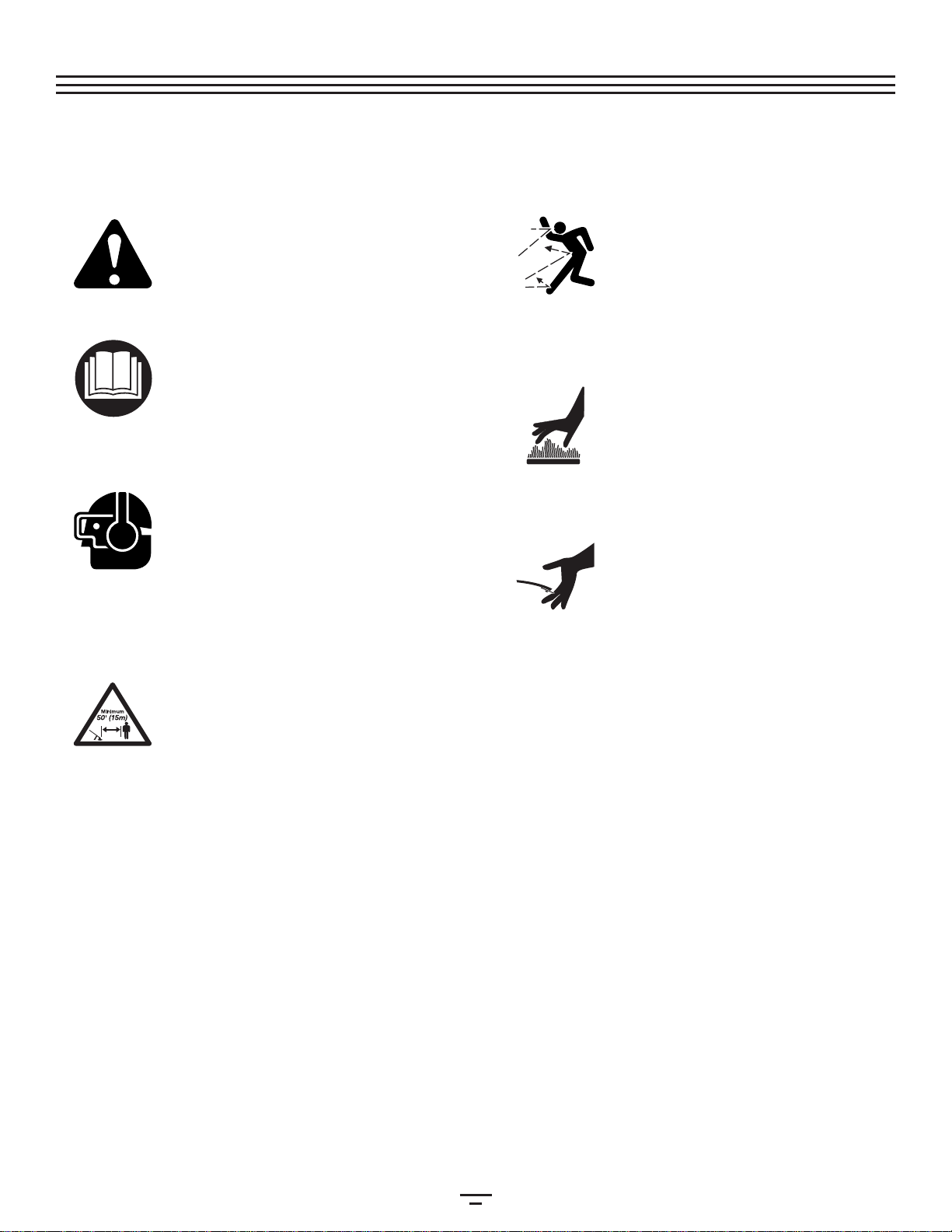
•Wear safety glasses or goggles that meet ANSI Z87.1 stan-
dards and are marked as such. Wear ear/hearing protection
when operating this unit. Wear a face or dust mask if the
operationis dusty.
•Wear heavy long pants, boots, gloves and a long sleeve
shirt. Do not wear loose clothing, jewelry, short pants, san-
dalsor go barefoot. Secure hair above shoulder level.
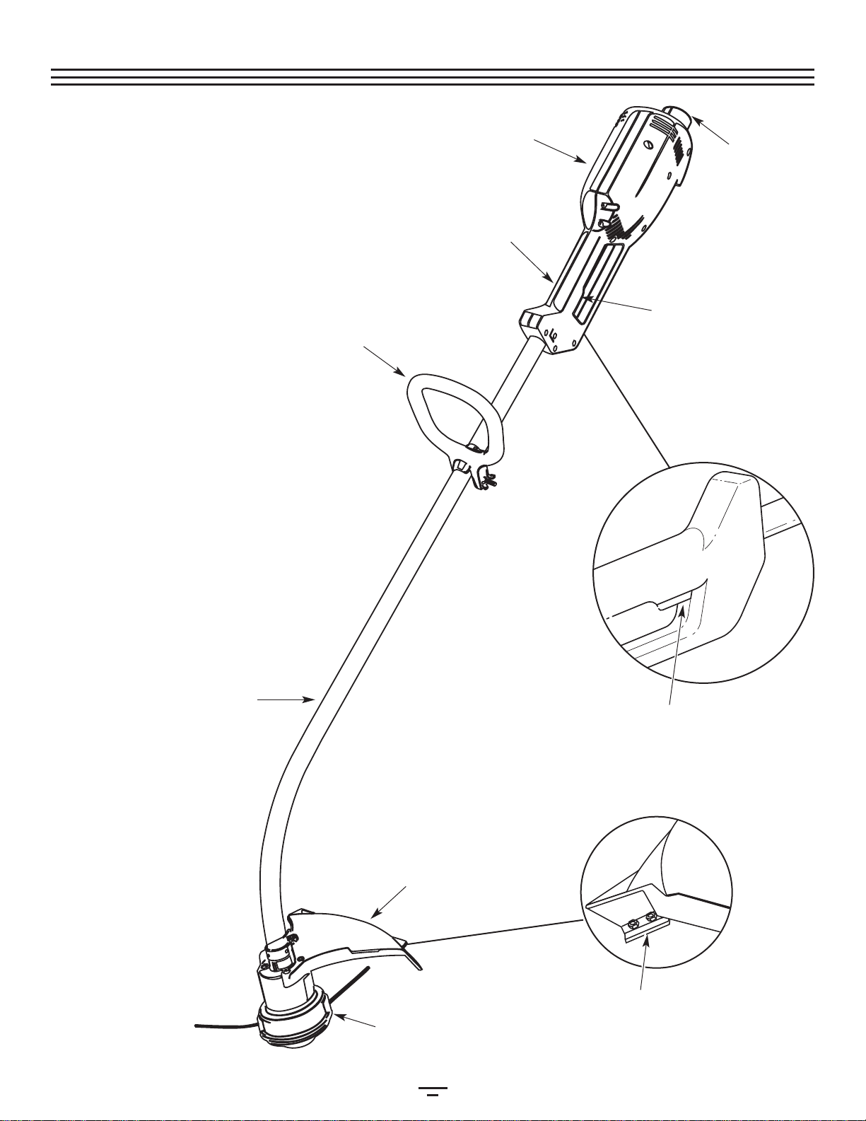
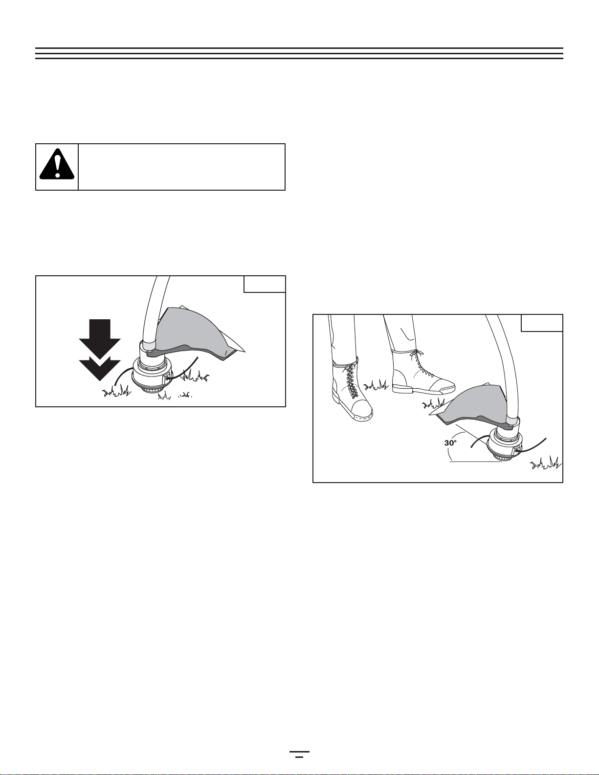
•The cutting attachment shield must always be in place while
operating the unit. Do not operate unit without both trim-
ming lines extended, and the proper line installed. Do not
extendthe trimming line beyond the length of the shield.
•Adjustthe D-handleto yoursize to provide the best grip.
•Be sure the cutting attachment is not in contact with any-
thingbefore starting the unit.
•Usethe unit only in daylight or good artificial light.
•Avoid accidental starting. Do not carry around a unit that is
plugged in with your finger on the trigger switch. Be sure
theswitch is in the off position when plugging in the unit.
•
Usethe right tool. Only use this tool for its intended purpose.
•Donot overreach. Always keep proper footing and balance.
•Always hold the unit with both hands when operating.
Keepa firm grip on both handles or grips.
•Keep hands, face, and feet at a distance from all moving
parts. Do not touch or try to stop the cutting attachment
whenit rotates.
•Always stop the motor when cutting is delayed or when
walkingfrom one cutting location to another.
•If you strike or become entangled with a foreign object,
stop the motor immediately and check for damage. Do not
operate before repairing damage. Do not operate the unit
withloose or damaged parts.
•Stopthe unit and unplug it for maintenance or repair.
•Use only genuine original equipment replacement parts
and accessories for this unit. These are available from your
authorized service dealer. Use of any non-original parts or
accessories could lead to serious injury to the user, or dam-
ageto the unit, and void your warranty.
•
Keep unit clean of vegetation and other materials. They may
becomelodged between the cutting attachment and shield.
OTHER SAFETYWARNINGS
•Disconnect the unit from the power supply when it is idle,
when you are storing or transporting it, when you are ser-
vicingit, and when you are changing attachments.
•Store the unit in a dry area, locked up to prevent unautho-
rized use or damage, and stored in a high place out of the
reachof children.
•Never douse or squirt the unit with water or any other liq-
uid. Keep handles dry, clean and free from debris. Clean
after each use. See the CleaningandStorage instructions.
•Keep these instructions. Refer to them often and use them
to instruct other users. If you loan someone this unit, also
loanthem these instructions.
SAVETHESE INSTRUCTIONS
WARNING: To reduce the risk of electrical shock,
use only SW-A, SOW-A, STW-A, STOW-A, SJW-A,
SJOW-A,SJTW-W or SJTOW-A cord types.
Cord length (ft.) 25 50 100 150
Wire size (AWG) 16 16 16 14
MINIMUM WIRE SIZE FOR EXTENSION CORDS FOR 120
VOLT APPLIANCES USING 0-6 AMPS
RULESFORSAFEOPERATION

5
SYMBOL MEANING
•SAFETY ALERT SYMBOL
Indicatesdanger, warning or caution.
Maybe used in conjunction with other
symbolsor pictographs.
•WARNING - READ
OPERATOR'S MANUAL
Readthe operator’s manual(s) and follow
allwarnings and safety instructions.
Failureto do so can result in serious
injuryto the operator and/or bystanders.
•WEAR EYE AND HEARING
PROTECTION
WARNING: Thrownobjects andloud
noisecan causesevere eyeinjury and
hearingloss. Weareye protection
meetingANSI Z87.1standards andear
protectionwhen operatingthis unit.Use
afull face shield when needed.
•KEEP BYSTANDERS AWAY
WARNING: Keepall bystanders,
especiallychildren and pets, at least 50
feet(15 m) from the operating area.
SYMBOL MEANING
•THROWN OBJECTS AND ROTATING
CUTTER CAN CAUSE SEVERE
INJURY
WARNING: Donot operate without the
cuttingattachment shield in place.
Keepaway from the rotating cutting
attachment.
•HOT SURFACEWARNING
Donottouchhotsurfaceslikethe gear
housing.Youmaygetburned.Theseparts
getextremelyhotfromoperation.They
remainhotforashorttimeaftertheunitis
turnedoff.
•SHARP BLADE
WARNING: Sharpblade on cutting
attachmentshield. To prevent serious
injury,do not touch line cutting blade.
SAFETY AND INTERNATIONAL SYMBOLS
Thisoperator's manual describes safety and international symbols and pictographs that may appear on this product.
Readthe operator's manual for complete safety, assembly, operating and maintenance and repair information.
RULESFORSAFEOPERATION

6
KNOWYOUR UNIT
As atrimmer:
•Cuttinggrass and light weeds
•Decorativetrimming around trees,fences,etc.
Cutting Attachment
Shield
D-Handle
Cutting Attachment
Shaft Housing
Line Cutting Blade
Housing Grip
Switch Trigger
Recessed
Plug
Motor Housing
RULESFORSAFEOPERATION
Switch Trigger

7
Fig.1
Onsome units, the D-handle may be pre-installed. In this
caseyou must loosen screws and adjust the handle to fit the
operator.Go to step 4 if the D-handle is pre-installed.
INSTALLING AND ADJUSTINGTHE D-HANDLE
1. Removethe items that were installed on the D-handle
forshipping.
2. Placethe D-handle over the shaft housing and push it on
theboom (Fig. 1).
3, Installthe bolt, washer and wing nut. Tighten them.
4. Ifthe D-handle was pre-installed, loosen the wing nut on
itjust enough so it is movable.
5. Whileholding the unit in the operating position, arrange
orrotate the D-handle to the location that provides you
thebest grip (Fig. 2).
6. Tightenthe wing nut until the D-handle is secure.
INSTALLINGTHE CUTTING SHIELD
Usethe following instructions if the cutting attachment shield
onyour unit is not installed or if you ever need to re-install it.
1. Placethe cutting attachment shield onto the shaft
housingabove the clamp assembly (Fig. 3).
2. Pushthe cutting attachment shield down to the top of
thecutting attachment assembly. Then rotate the shield
untilits screw holes line up with the holes in the cutting
attachment.The shield guard should fit into the recessed
pocket(Fig. 3).
3. Installthe screws with a Phillips screwdriver (Fig. 4).
WARNING: To prevent serious personal injury,
never operate the trimmer without the cutting
attachmentshield in place.
Fig.2
Clamp
Assembly
Cutting
Attachment
Shaft Housing
(4) Screws
Cutting Attachment
Shield
Fig.3
Fig.4
ASSEMBLYINSTRUCTIONS

8
CONNECTINGTHE CORD
Usethe cord hook when connecting the extension cord to the
powercord outlet. This helps prevent any disconnection.
1. Makea narrow loop with the extension cord.
2. Pushthe loop through the opening and move it onto the
hookon the motor housing (Fig. 5).
3. Plugthe cord properly into the socket.
Onlyuse outdoor-approved extension cords. Cord sets are
specifiedin theImportantSafety Information section.
STARTING/STOPPING INSTRUCTIONS
Oncethe unit is plugged in, stand in the operating position
(Fig.7). Squeezethe triggerto startthe unit. Tostop theunit,
releasethe trigger (Fig. 6).
WARNING: Always wear eye, hearing, foot and
body protection to reduce the risk of injury
whenoperating this unit.
HOLDINGTHE UNIT
Beforeoperating the unit, stand in the operating position
(Fig.7). Check for the following:
•
Theoperator is wearing eye protection and proper clothing
•Witha slightly-bent right arm, the operator’s hand is
holdingthe shaft grip
•Theoperator’s left arm is straight, the left hand holding
theD-handle
•Theunit is at waist level
•
Thecutting attachment is parallel to the ground and eas-
ilycontacts the grass without the need to bend ove
r
Trigger
ADJUSTINGTRIMMING LINE LENGTH
TheBumpHead™cuttingattachmentallows you to release
trimminglinewithoutstoppingthemotor. To release moreline,
lightlytapthecuttingattachmenton the ground (Fig.8)while
operatingthetrimmerathighspeed.
NOTE: Always keep the trimming line fully extended.
Line release becomes more difficult as cutting
linebecomes shorter
Eachtime the head is bumped, about 1 inch (25.4 mm) of
trimmingline releases. A blade in the cutting attachment
shieldwill cut the line to the proper length if any excess line
isreleased.
Fig.7
Fig.6
Fig.5
WARNING: Always wear eye, hearing, foot and
body protection to reduce the risk of injury
whenoperating this unit.
OPERATINGINSTRUCTIONS

9
•Cutfromlefttorightwheneverpossible.Cuttingtotheright
improvestheunit'scuttingefficiency.Clippingsarethrown
awayfromtheoperator.
•Slowly move the trimmer into and out of the cutting
area at the desired height. Move either in a forward-
backward or side-to-side motion. Cutting shorter
lengths produces the best results.
•Trimonly when grass and weeds are dry.
•Thelife of your cutting line is dependent upon:
•Following the trimming techniques previously explained
•What vegetation is cut
•Where vegetation is cut
Forexample, the line will wear faster when trimming against
afoundation wall as opposed to trimming around a tree.
DECORATIVETRIMMING
Decorativetrimming is accomplished by removing all
vegetationaround trees, posts, fences and more.
Rotatethe whole unit so that the cutting attachment is at a
30°angle to the ground (Fig. 9).
TIPS FOR BESTTRIMMING RESULTS
•Keepthe cutting attachment parallel to the ground.
•Donotforcethecuttingattachment.Allowthetipoftheline
todothecutting,especiallyalongwalls.Cuttingwithmore
thanthetipwillreducecuttingefficiencyandmayoverload
themotor.
•Cutgrassover8inches(200 mm) by workingfromtopto
bottominsmallincrementstoavoid premature line wear
ormotordrag.
Forbest results, tap the bump knob on bare ground or hard soil.
Ifyou attempt a line release in tall grass, the unit may stall.
Alwayskeep the trimming line fully extended. Line release
becomesmore difficult when the cutting line gets shorter.
NOTE: Do not rest the Bump Head™ on the ground
whilethe unit is running.
Someline breakage will occur from:
•Entanglementwith foreign matter
•Normalline fatigue
•Attemptingto cut thick, stalky weeds
•
Forcingthe line into objects such as walls or fence posts
CAUTION:
Do not remove or alter the line cutting
blade assembly. Excessive line length will make the
unit overheat. This may lead to serious personal
injuryordamage totheunit.
Fig.9
Fig.8
OPERATINGINSTRUCTIONS

10
SERVICING DOUBLE INSULATED UNITS
Thisunit is double-insulated. In a double-insulated unit, two
systemsof insulation are provided instead of grounding.
Thereis no grounding provided and no means of grounding
shouldbe added to this unit.
Extremecare and knowledge of the system is required when
servicinga double-insulated unit. Service should be
performedby qualified service personnel only. Replacement
partsfor a double-insulated unit must be identical to the
partsthey replace. Refer any repair to an authorized service
dealer.A double-insulated unit is marked with the words
“doubleinsulation” or “double insulated.”
LINE INSTALLATION
Thissection covers both SplitLine™ and standard single line
installation.
Always use genuine factory parts 0.065 in. (1.65 mm)
replacementline. Using line other than the specified may
makethe unit overheat or fail.
Thereare two methods to replace the trimming line:
•Wind the inner reel with new line
•Install a prewound inner reel
Winding the Existing Inner Reel
1. Holdthe outer spool with one hand and unscrew the
bumpknob counterclockwise (Fig. 10). Inspect the bolt
insidethe bump knob to make sure it moves freely.
Replacethe bump knob if damaged.
2. Removethe inner reel from the outer spool (Fig. 11).
3. Removespring from the inner reel (Fig. 11).
4. Usea clean cloth to clean the inner reel, spring, shaft, and
innersurface of the outer spool.
5. Checkthe indexing teeth on the inner reel and outer
spoolfor wear (Fig. 12). If necessary, remove burrs or
replacethe reel and spool.
Bump Knob
Bolt
Loop
NOTE: SplitLine™ can only be used with the inner reel
with the slotted holes. Single line can be used
on either type of inner reel. Use Figure 13 to
identifythe inner reel you have.
NOTE: Always use the correct line length when
installing trimming line on the unit. The line may
notrelease properly if the line is too long.
Inner Reel
Spring
Outer Spool
Indexing Teeth
Slotted Holes
For Use with SplitLine™
or Single Line
For Use with
Single Line ONLY
WARNING: Never use metal-reinforced line,
wire, chain or rope. These can break off and
becomedangerous projectiles.
Fig.14
Fig.13
Fig.12
Fig.11
Fig.10
MAINTENANCE& REPAIRINSTRUCTIONS

11
Single Line Installation
GoToStep8forSplitLine™Installation
6. Cutapproximately 25 feet (7.6 m) of new trimming line,
thenloop it into two equal lengths. Insert each end of the
linethrough one of the two holes in the inner reel
(Fig. 14). Pull the line through the inner reel so that the
loopis as small as possible.
7. Windthe lines in tight even layers, onto the reel
(Fig.15). Wind the line in the direction indicated on the
innerreel. Place your index finger between the two lines
tostop the lines from overlapping. Do not overlap the
endsof the line. Proceed to step 11.
SplitLine™ Installation
8. Cutapproximately 12 feet (3.65 m) of new trimming line.
Insertone end of the line through one of the two holes in
theinner reel (Fig. 16). Pull the line through the inner reel
untilonly about 4 inches is left out.
9. Insertthe end of the line into the open hole in the inner
reeland pull the line tight to make the loop as small as
possible(Fig. 16).
10. Beforewinding, split the line back about 6 inches.
11. Windthe line in tight even layers in the direction
indicatedon the inner reel.
NOTE:
Failure to wind the line in the direction indicated will
causethe cutting attachment tooperateincorrectly
.
12. Insertthe ends of the line into the two holding slots (Fig. 17).
Loop
13. Insertthe ends of the line through the eyelets in the
outerspool and place inner reel with spring inside the
outerspool (Fig. 18). Push the inner reel and outer spool
together.While holding the inner reel and outer spool,
graspthe ends and pull firmly to release the line from the
holdingslots in the reel.
NOTE: The spring must be assembled on the inner reel
beforereassembling the cutting attachment.
14. Holdthe inner reel in place and install the bump knob by
turningclockwise. Tighten securely.
INSTALLING A PREWOUND REEL
1. Holdthe outer spool with one hand and unscrew the
bumpknob counterclockwise (Fig. 10). Inspect the bolt
insidethe bump knob to make sure it moves freely.
Replacethe bump knob if damaged.
2. Removethe old inner reel from the outer spool (Fig. 11).
3. Removethe spring from the old inner reel (Fig. 11).
4. Placethe spring in the new inner reel.
NOTE: The spring must be assembled on the inner reel
beforereassembling the cutting attachment.
5. Insertthe ends of the line through the eyelets in the
outerspool (Fig. 18).
6. Placethe new inner reelinsidetheouterspool.Pushthe
innerreel and outer spooltogether.Whileholdingtheinner
reeland outer spool, grasptheendsandpullfirmlyto
releasethe line from theholdingslotsinthereel.
7. Holdthe inner reel in place and install the bump knob by
turningclockwise. Tighten securely.
Replacement Parts
Refer to the Accessories/ReplacementParts section.
Holding Slots
Spring
Eyelet
Eyelet
Fig.15
Fig.18
Fig.17
Fig.16
MAINTENANCE& REPAIRINSTRUCTIONS

12
CLEANING
Switchoff the unit and disconnect it from the power source.
Usea small brush to clean off the outside of the unit. Do not
usestrong detergents. Household cleaners that contain
aromaticoils such as pine and lemon, and solvents such as
kerosene,can damage plastic housing or handle. Wipe off
anymoisture with a soft cloth. Also keep the air vents free of
obstructions.
INSPECT EXTENSION CORDS
Inspectall extension cords. Look closely for deterioration,
cutsor cracks in the insulation. Inspect the connectors for
damage.Replace a damaged or defective cord.
WARNING: To avoid serious personal injury,
always turn your trimmer off and allow it to cool
beforeyou cleanor serviceit.
STORAGE
•Allowthe unit to cool before storing.
•Lockthe unit to prevent unauthorized use or damage.
•Storethe unit in a dry, well-ventilated area.
•Storethe unit out of the reach of children.
ACCESSORIES/REPLACEMENT PARTS
Replacement Line . . . . . . . . . . . . . . . . . . . . . . . . . . . . . . . . . 160425
Replacement Line Cartridge . . . . . . . . . . . . . . . . . . . . . . . . 160425
Inner Reel Spring . . . . . . . . . . . . . . . . . . . . . . . . . . . . . . . . . . . 610317
Bump Knob . . . . . . . . . .. . . . . . . . . . . . . . . . . . . . . . . . . . . . . . 153066
Bump Knob Assembly . . . . . . . . . . . . . . . . . . . . . . . . . . . . . . 147153
Thesereplacement parts can be purchased from your local
authorizeddealer.
MOTOR
Motortype....................................................................................................................................................................................A.C.,120Volts Electric
OperatingRPM..................................................................................................................................................................................... up to 7,400 rpm
IgnitionSwitch........................................................................................................................................................................................................Trigger
Amperage............................................................................................................................................................................................................. 4.7 amps
DRIVE SHAFT AND CUTTING HEAD
DriveShaftHousing........................................................................................................................................................................................Aluminum
ShoulderStrap.................................................................................................................................................................................................... Optional
UnitWeight(cutting attachment shield and D-handle)...............................................................................................................9 lbs.(4.1 kg)
LineSpool....................................................................................................................................................................................... Bump Line Releaser
LineSpool Diameter......................................................................................................................................................................3 inches (76.2mm)
Cutting Path Diameter......................................................................................................................................................................... 15 in (381 mm)
Trimming Line Diameter.............................................................................................................................................................. 0.065 in (1.65 mm)
MAINTENANCE& REPAIRINSTRUCTIONS
SPECIFICATIONS

13
CAUSE ACTION
Unitis unplugged Check cord to make sure it is still plugged into an electrical outlet
MOTOR WILL NOT START
CAUSE ACTION
Cuttingattachment bound with grass Stop the unit and clean cutting attachment
Cuttingattachment out of line Refill with new line
Innerreel bound up Replace the inner reel
Cuttinghead dirty Clean inner reel and outer spool
Linewelded Disassemble, remove the welded section and rewind
Linetwisted when refilled Disassemble and rewind the line
Notenough line is exposed Push the bump knob and pull out line until 4 inches (102 mm) of line
isoutside of the cutting attachment
CAUSE ACTION
Oil,cleaner or lubricant in cutting head Clean and thoroughly dry the cutting head
If further assistance is required, contact your authorized service dealer
CUTTING ATTACHMENTWILL NOT ADVANCE LINE
CUTTING LINE ADVANCE UNCONTROLLABLY
TROUBLESHOOTING

SAVETHESE INSTRUCTIONS FOR FUTURE REFERENCE
FOR QUESTIONS CALL 1-866-840-6483
OPERATOR’S MANUAL PART NO. 769-00431 9/02
PRINTED IN U.S.A.
MANUFACTURER’S LIMITEDWARRANTY FOR:
No implied warranty, including any implied warranty of
merchantability or fitness for a particular purpose,
applies after the applicable period of express written
warranty above as to the parts as identified. No other
express warranty or guaranty, whether written or oral,
except as mentioned above, given by any person or
entity, including a dealer or retailer, with respect to any
product shall bind Troy-Bilt LLC. During the period of
the Warranty, the exclusive remedy is repair or
replacement of the product as set forth above. (Some
states do not allow limitations on how long an implied warranty
lasts,so the above limitation may not apply to you.)
The provisions as set forth in this Warranty provide the
sole and exclusive remedy arising from the sales. Troy-Bilt
LLC shall not be liable for incidental or consequential loss
or damages including, without limitation, expenses
incurred for substitute or replacement lawn care services,
for transportation or for related expenses, or for rental
expenses to temporarily replace a warranted product.
(Some states do not allow limitations on how long an implied
warrantylasts, so the above limitation may not apply to you.)
In no event shall recovery of any kind be greater than the
amount of the purchase price of the product sold.
Alteration of the safety features of the product shall void
this Warranty. You assume the risk and liability for loss,
damage, or injury to you and your property and/or to others
and their property arising out of the use or misuse or inabili-
tyto use the product.
This limited warranty shall not extend to anyone other than
the original purchaser, original lessee or the person for
whomit was purchased as a gift.
How State Law Relates to this Warranty:This warranty
gives you specific legal rights, and you may also have other
rightswhich vary from state to state.
Tolocate your nearest service dealer dial 1-866-840-6483.
TROY-BILT LLC
POBox361131
Cleveland,OH 44136-0019 U.S.A.
The limited warranty set forth below is given by Troy-Bilt
LLC with respect with new merchandise purchased and
usedin the United States, its possessions and territories.
Troy-Bilt warrants this product against defects in material
and workmanship for a period of two (2) years commencing
on the date of original purchase and will, at its option, repair
or replace, free of charge, any part found to be defective in
material or workmanship. This limited warranty shall only
apply if this product has been operated and maintained in
accordance with the Operator’s Manual furnished with the
product, and has not been subject to misuse, abuse, com-
mercial use, neglect, accident, improper maintenance, alter-
ation, vandalism, theft, fire, water or damage because of
other peril or natural disaster. Damage resulting from the
installation or use of any accessory or attachment not
approved by Troy-Bilt for use with the product(s) covered by
thismanual will void your warranty as to any resulting damage.
This warranty is limited to ninety (90) days from the date of
original retail purchase for any Bolens product that is used
for rental or commercial purposes, or any other income-pro-
ducingpurpose.
HOW TO OBTAIN SERVICE: Warranty service is available,
WITH PROOF OF PURCHASE THROUGH YOUR LOCAL
AUTHORIZED SERVICE DEALER. To locate the dealer in your
area, please check for a listing in the Yellow Pages or con-
tact the Customer Service Department of Troy-Bilt LLC by
calling 1-866-840-6483 or writing to PO Box 361131,
Cleveland, Ohio 44136-0019. No product returned directly
to the factory will be accepted unless prior written permis-
sion has been extended by the Customer Service
Departmentof Troy-Bilt LLC.
This limited warranty does not provide coverage in the
following cases:
A.Tune-ups - Spark Plugs, Carburetor Adjustments, Filters
B.Wear items - Bump Knobs, Outer Spools,CuttingLine,
InnerReels, Starter Pulley, Starter Ropes, Drive Belts
C.Troy-Bilt does not extend any warranty for products
soldor exported outside of the United States of
America,its possessions and territories, except those
soldthrough Troy-Bilt’s authorized channels of export
distribution.
Trot-Bilt reserves the right to change or improve the design of
any Bolens Product without assuming any obligation to modify
anyproduct previously manufactured.

Manuelde
L’utilisateur
Depuisqu’elleacommencéàfabriquerdes
outilsdejardinen1850,lasociétéBolensest
connuepourladurabilitéetlafiabilitédeses
produits.Bolens aperpétuécettetradition
dansl’industriedesoutilsmotorisésd’extérieur
lorsqu’elleaconçuetconstruitlepremier
tracteurdejardinmotorisé.
Denosjourslesamateursdejardinagedu
paystoutentiercomptentsurBolenspour
leurfournirdesoutilsmotorisésdurableset
fiablesàdesprixabordables.
DésherbeuseElectrique
Model BL50

F2
TOUS NOS REMERCIEMENTS
Nousvous remercions d'avoir acheté ce produit de qualité.
Cetoutil mécanique de plein air moderne est conçu pour
vousrendre service pendant longtemps. Il vous sauvera
beaucoupde temps comme vous pourrez vous en rendre
compte.Ce manuel de l'utilisateur comporte un mode
d'emploifacile à comprendre. Prenez soin de lire le manuel
aucomplet et suivez toutes ses instructions à la lettre afin de
conservervotre nouvel outil mécanique de plein air en
excellentétat de fonctionnement.
RÉFÉRENCES,ILLUSTRATIONS ET SPÉCIFICATIONS
RELATIVES AU PRODUIT
Toutesles informations, illustrations et spécifications
contenuesdans ce manuel tiennent compte des dernières
informationstechniques disponibles au moment de mettre
souspresse. Nous nous réservons le droit d'y apporter des
modificationsà tout moment, sans préavis.
Copyright©2002 MTD SOUTHWEST INC Tous droits réservés.
BumpHeadMC est une marque de commerce de MTD
SOUTHWESTINC
SplitLineMC estune marque de commerce de MTD
SOUTHWESTINC
NFORMATIONS D’ENTRETIEN
Toutentretien effectué sur cet appareil pendant et après la
périodede garantie doit être fait par un concessionnaire
agrééuniquement. Obtenez la liste des concessionnaires
agréés appelez le 1-330-558-7220 ou1-866-840-6483.
NERETOURNEZ PAS L'APPAREIL AU DÉTAILLANT CHEZ QUI
VOUSL'AVEZ ACHETÉ. TOUT SERVICE SOUS GARANTIE
NÉCESSITEUNE PREUVE D'ACHAT.
Avantd'assembler votre nouvel équipement, repérez la
plaquesignalétique de l'appareil et copiez ses informations
dansl'espace ci-dessous. Ces informations sont essentielles si
vousdésirez obtenir de l'aide auprès de notre service
techniqueou d'un distributeur agréé. Un exemple de plaque
signalétiqueest présenté ci-dessous.
Copiez le numéro
de modèle / pièce ici :
Copiez le numéro de
modèle / pièce mère ici :
Numéro de modèle / pièce mère
Numéro de série
TABLE DES MATIÈRES
Servicetechnique . . . . . . . . . . . . . . . . . . . . . . . . . . . . . . .. . . . . .2
Consignesde sécurité . . . . . . . . . . . . . . . . . . . . . . . . . . . . . .. . .3
Familiarisez-vousavec votre appareil . . . . . . . . . . . . . . . . . .6
Instructionsde montage . . . . . . . . . . . . . . . . . . . . . . . . . . . . . .7
Moded'emploi . . . . . . . . . . . . . . . . . . . . . . . . . . . . . . .. . . . . . . . .8
Entretienet réparations . . . . . . . . . . . . . . . . . . . . . . . . . . . . . .10
Accessoires/piècesde rechange . . . . . . . . . . . . . . . . . . . . . .12
Nettoyageet entreposage . . . . . . . . . . . . . . . . . . . . . . . . . . .12
Caractéristiques . .. .. .. .. .. .. .. .. .. .. .. .. .. .. .. .. .. .. .12
Tableaude dépannage . . . . . . . . . . . . . . . . . . . . . . . . . . . . . ..13
Garantie .. . . . . . . . . . . . . . . . . . . . . . . . . . . . . . .. . . . . . . . . . . . .14
Liste despièces . .. . .. .Intérieurede laCouverture Arrière
CONTENU DE L'EMBALLAGE
•Désherbeuse modèle BL50 avec accessoire de coupe
BumpHeadMC
∆Poignéeen D et visserie
∆Protecteurd'accessoire de coupe et visserie
•Manuelde l'utilisateur
•Carted'enregistrement du produit
∆Cetélément est installé soit sur l’appareil soit sur
l’ensemblede visserie.
Prenezsoindelireetdebiencomprendrecemanuelavantde
démarreroudefairefonctionnercetéquipement.
CEPRODUIT EST COUVERT PAR UN OU PLUSIEURS BREVETS
AMÉRICAINS,ET D’AUTRES SONT EN INSTANCE
INTRODUCTION

F3
DANGER: le non-respect d’un avertissement
peut causer dommages matériels ou blessures
graves pour tous. Respectez les consignes de
sécurité afin de réduire les risques d'incendie,
d'électrocutionet de blessures.
AVERTISSEMENT: le non-respect d’un aver-
tissement peut causer dommages matériels ou
blessures graves pour tous. Respectez les con-
signes de sécurité afin de réduire les risques
d'incendie,d'électrocution et de blessures.
MISE EN GARDE: le non-respect d’un avertisse-
ment peut causer dommages matériels ou
blessures graves pour tous. Respectez toujours les
consignes de sécurité afin de réduire les risques
d'incendie,d'électrocution et de blessures.
SYMBOLE ALERTE DE SÉCURITÉ: indique un
danger, un avertissement ou une mise en garde.
Soyez vigilant afin d'éviter toute blessure grave.
Ce symbole peut être combiné à d'autres sym-
bolesou pictogrammes.
Lisez le(s) manuel(s) de l'utilisateur et suivez tous les avertissements et consignes de sécurité. Vous pourriez à défaut
entraîner des blessures graves pour vous ou d'autres personnes.
SIVOUS AVEZ DES QUESTIONS,APPELEZ LE
1-330-558-7720 ou 1-866-840-6483
• SYMBOLES DE SÉCURITÉ •
• IMPORTANTES CONSIGNES DE SÉCURITÉ •
LIRE TOUTES LES INSTRUCTIONS
Lessymboles de sécurité attirent votre attention sur des dangers potentiels. Ces symboles et leurs détails explicatifs méritent que
vousles lisiez et compreniez bien. Les avertissements de sécurité ne peuvent éviter les dangers de par eux-mêmes. Les consignes
oumises en garde qu'ils donnent ne remplacent pas des mesures préventives appropriées contre les accidents.
SYMBOLE SIGNIFICATION SYMBOLE SIGNIFICATION
REMARQUE: donnedes informations ou des instructions vitales pour le fonctionnement ou l'entretien de l'équipemen
AVANT UTILISATION
•Veuillez lire les instructions avec soin. Familiarisez-vous avec les
commandeset l'utilisation correcte de cet appareil.
•N'utilisez pas l'appareil si vous êtes fatigué, malade ou sous l'effet
del'alcool, de drogues ou de médicaments.
•
Les enfants et adolescents de moins de 15 ans ne doivent pas utiliser
l'appareilexceptés les adolescents assistés d'un adulte.
•Inspectez l'appareil avant utilisation. Remplacez les pièces
endommagées.. Assurez-vous que les fixations sont solidement en
place. Remplacez les pièces de l'accessoire de coupe qui sont
fendillées, ébréchées ou endommagées. Assurez-vous que
l'accessoire de coupe est correctement installé et solidement fixé.
Assurez-vous que le protecteur d'accessoire de coupe est
correctement fixé et positionné comme recommandé. Vous risquez
sinon de causer des blessures à l'opérateur et aux spectateurs, et
d'endommagerl'appareil.
•N'utilisez que du fil de remplacement d'origine de 1,65 mm
(0,065 po) de diamètre. N'utilisez jamais de fil, de chaîne ou de
cordon à renfort métallique car ils peuvent se briser et se
transformeren projectile dangereux.
•Soyez conscient des risques de blessure à la tête, aux mains et aux
pieds.
•Dégagez la zone de coupe avant chaque usage. Enlevez tous les
objets pouvant être projetés ou happés par l'accessoire de coupe :
cailloux, verre brisé, clous, fil ou ficelle. Éloignez enfants, spectateurs
et animaux de la zone de coupe. Tenez-les à au moins 15 m (50 pi) de
là mais sachez que les spectateurs risquent quand même d'être
atteints par des objets projetés. Les spectateurs doivent porter des
protections oculaires. Arrêtez immédiatement le moteur et
l'accessoirede coupe si quelqu'un s'approche de vous.
•Cet appareil n'est pas conçu pour servir de débroussailleuse.
N'utilisez cet appareil avec aucun type de lame ou d'accessoire de
débroussaillage.
RECOMMANDATIONS ELECTRIQUES EN MATIERE DE
SECURITE
•Cet outil comporte une isolation double. Pour toutes les
réparations, utilisez uniquement des pièces de rechange
identiques. Tout cordon électrique endommagé doit être réparé
ouremplacé.
•A. Comme cet outil comporte une isolation double, il est donc
possible d’utiliser des rallonges à 2 conducteurs (rallonges sans
terre). Cependant, il est tout à fait possible d’utiliser des rallonges
à 3 conducteurs (rallonges avec fil de terre), qui comportent des
fiches de type NEMA (fiches parallèles, fiche terre en forme de U).
Ces rallonges sont disponibles auprès de votre revendeur local.
Veillez à n’utiliser que des rallonges à section circulaire,
approuvéespour une utilisation extérieure.
AVERTISSEMENT: Pour réduire le risque d’in-
cendie, de choc électrique et de préjudice cor-
porel, veillez à toujours respecter les précautions
élémentaires de sécurité, chaque fois que vous
utilisez des outils de jardinage électriques. Avant
d’utiliser votre taille haies, veillez à lire soigneuse-
ment et à bien comprendre son manuel d’utilisa-
tion. Focalisez votre attention plus particulière-
ment sur les instructions de fonctionnement et les
recommandationsde sécurité.
CONSIGNESDESÉCURITÉ

F4
•Pour réduire le risque de choc électrique, cet appareil est pourvu
d’une fiche polarisée (une lame est plus large que l’autre). Cet
appareil ne peut être inséré dans une prise polarisée que d’une seule
manière. S’il n’est pas possible d’insérer entièrement la fiche dans la
prise, essayez de brancher la fiche dans l’autre sens. Si malgré tout, il
n’est pas possible d’insérer la fiche, remplacez le cordon par un
cordon qui comporte les bonnes fiches. Ne modifiez cet appareil en
aucuncas.
•JEUX DE CORDONS: Vérifiez que votre jeu de cordons est en bon
état de fonctionnement. Si vous utilisez un jeu de cordons,
assurez vous de bien utiliser un cordon de calibre suffisant pour
laisser passer le courant de charge de votre appareil. Un jeu de
cordons à section trop faible risque de provoquer des chutes de
tension de ligne, qui entraînent une perte de puissance et une
surchauffe. Le tableau ci-dessous donne les calibres corrects à
utiliser, en fonction de la longueur du cordon et de la valeur de
l’intensité nominale. En cas de doute, utilisez la section de câble
immédiate-ment supérieure. Un numéro de calibre faible
correspond à une forte section de câble. Référez vous à la Mode
D’emploi pour réduire le risque de débranchement du cordon de
l’appareilpendant le fonctionnement, du jeu de cordons.
•Le(s) circuit(s) électrique(s) ou la(les) prise(s) d’alimentation de cet
outil de jardinage doit(doivent) comporter une protection de type
GFCI (qui coupe le circuit en cas de défaut de terre). Il existe des
prises qui comportent une protection GFCI, et que l’on peut
utiliserdans ce cas de figure.
•Votre appareil est pourvu d’une plaquette du constructeur, qui
indique le type de tension à utiliser. N’alimentez jamais cet appareil
avecune tension alternative différente de celle affichée.
•Procédez à une inspection périodique de vos rallonges
électriques et de la fiche de raccord de votre appareil. Examinez
plus particulièrement l’isolation qui ne doit pas présenter de
traces de détérioration, de coupures ou de mise à nu. Inspectez
également les raccords qui doivent être en bon état. Si les
cordonsparaissent endommagés, remplacez les ou réparez les.
•Evitez d’utiliser cet appareil dans des conditions dangereuses. Ne le
faites jamais fonctionner en atmosphère humide ou mouillée.
L’humiditéconstitue un danger réel de choc électrique.
•N’utilisezpas cet appareil sous la pluie.
•Ne touchez pas la fiche ou l’appareil lui même si vos mains sont
mouillées.
PENDANT L'UTILISATION DE L'APPAREIL
•Portez des lunettes de sécurité conformes aux normes ANSI Z87.1
ainsi que des protège-oreilles durant l'utilisation de l'appareil.
Portez un masque facial ou antipoussières si vous travaillez dans
unlieu poussiéreux.
•Portez des pantalons épais et longs, des bottes, des gants et une
chemise à manches longues. Ne marchez pas pieds nus et évitez
les vêtements lâches, bijoux, pantalons courts et sandales.
Relevezles cheveux au-dessus des épaules.
•Le protecteur d'accessoire de coupe doit toujours être en place
lors de l'utilisation de l'appareil. Ne faites pas marcher l'appareil
sans que les deux fils soient bien déployés, en supposant qu'un fil
approprié a été installé. Assurez-vous que le fil ne dépasse pas le
protecteurde sécurité.
•
Ajustezla poignée en D selon votre taille pour mieux l'agripper.
•N'utilisezl'appareil qu'en plein jour ou avec un bon éclairage artificiel.
•Évitez tout démarrage accidentel. Ne transportez pas l'appareil
branché, le doigt sur l’interrupteur. Mettez ce dernier hors tension
avantde brancher.
•Ne vous étirez pas. Tenez-vous toujours bien sur vos pieds en
positiond'équilibre.
•Tenez toujours l'appareil des deux mains lorsque vous le faites
marcher.Agrippez fermement les poignées avant et arrière.
•Gardez les mains, le visage et les pieds éloignés des pièces
mobiles. Ne touchez pas et n'essayez pas d'arrêter l'accessoire de
coupeen rotation.
•Servez-vous des outils appropriés. N'utilisez cet outil que pour son
usageprévu.
•Ne faites pas fonctionner le moteur à un régime plus élevé que
nécessaire pour couper, tailler ou faire les bordures. Ne faites pas
tournerle moteur à haut régime si vous ne vous faites pas de coupe.
•
Arrêtez toujours le moteur lorsque vous suspendez la coupe ou
lorsquevous vous déplacez d'un lieu de travail vers un autre.
•Si vous heurtez un corps étranger ou que celui-ci est happé,
arrêtez le moteur immédiatement et vérifiez que rien n'a été
endommagé. Ne faites pas fonctionner avant réparation des
dommages. Ne faites pas marcher l'appareil si les pièces sont
desserréesou endommagées.
•Arrêtez et éteignez le moteur dans les cas suivants: entretien,
réparationou changement d'accessoires ou autres.
•N'utilisez que des pièces de rechange et accessoires d'origine
pour cet appareil. Elles sont disponibles auprès de votre
concessionnaire agréé. L'utilisation de pièces ou accessoires
autres que ceux de original peut causer des blessures graves,
endommagerl’appareil et annuler sa garantie.
•Gardez l'appareil exempt d'accumulation de végétation ou autres
matières. Celles-ci peuvent rester logées entre l'accessoire de
coupeet le protecteur.
AUTRES AVERTISSEMENTS DE SÉCURITÉ
•N'entreposez jamais l'appareil rempli de carburant dans un édifice
où les vapeurs peuvent atteindre une source de flammes vives ou
d'étincelles.
•Laissez le moteur se refroidir avant de l'entreposer ou de le
transporter.Attachez bien l'appareil pendant le transport.
•Rangez l'appareil dans un endroit verrouillé et sec, ou élevé et sec,
hors de portée des enfants, pour éviter une utilisation indésirable
ouun accident.
•Ne trempez et n'arrosez jamais l'appareil avec de l'eau ou tout
autre liquide. Gardez les poignées sèches, propres et exemptes de
débris. Nettoyez après chaque usage. Voir les sections Nettoyage
etEntreposage.
•Conservez ces instructions. Consultez-les souvent et servez-vous
en pour instruire d'autres usagers. Si vous prêtez l'appareil à
quelqu'un,prêtez-lui également ces instructions.
CONSERVEZ CES INSTRUCTIONS
AVERTISSEMENT:
Pour réduire le risque de choc
électrique, utilisez uniquement des rallonges élec-
triques approuvées pour une utilisation extérieure.,
comme par exemple les rallonges à cordons de type
SW-A, SOW-A, STW-A, STOW-A, SJW-A, SJOW-A, SJTW-
Wou SJTOW
.
Long. de cordon (pieds)
25 50 100 150
Calibre du cordon (AWG)
16 16 16 14
CALIBRE MINIMUM DES RALLONGES ALIMENTANT DES APPAREILS
120V, A COURANT DE CHARGE DE 0-6
AMPS
CONSIGNESDESÉCURITÉ

F5
SYMBOLE SIGNIFICATION
•SYMBOLE ALERTE DE SÉCURITÉ
Indiqueun danger, un avertissement ou
unemise en garde. Ce symbole peut être
combinéà d'autres symboles ou
pictogrammes.
•AVERTISSEMENT - LISEZ LE
MANUEL DE L'UTILISATEUR
Lisezle manuel de l'utilisateur et suivez
tousles avertissements et consignes de
sécurité.Vous pourriez à défaut entraîner
desblessures graves pour vous ou
d'autrespersonnes.
•PORTEZ DES PROTECTIONS (YEUX
ET OREILLES)
AVERTISSEMENT: lesobjets projetés et
lesbruits forts peuvent endommager la
vueet l’ouïe. Portez une visière de norme
ANSIZ87.1-1989 et des protège-oreilles
pendantl'utilisation.
•ÉLOIGNEZ LES SPECTATEURS
AVERTISSEMENT: éloigneztout
spectateur,les enfants et les animaux
domestiquesen particulier, d'au moins
15 m(50 pi) de la zone de coupe.
SYMBOLE SIGNIFICATION
•LES OBJETS PROJETÉS ET LATÊTE
ROTATIVE PEUVENT CAUSER DES
BLESSURES GRAVES
AVERTISSEMENT: nefaites pas
fonctionnersans protecteur de sécurité
enplastique. Tenez-vous à l'écart de
l'accessoirede coupe rotatif.
•AVERTISSEMENT SURFACE CHAUDE
Netouchez les pièces chaudes. Vous
pourriezvous brûler. Ces pièces
deviennenttrès chaudes à l'utilisation.
Ellesrestes chaudes brièvement après
l'arrêt.
•LAME AIGUISÉE
AVERTISSEMENT: leprotecteur
d'accessoirede coupe comporte une
lameaiguisée. Ne touchez pas la lame
pouréviter des blessures graves.
SYMBOLES DE SÉCURITÉ ET INTERNATIONAUX
Cemanuel de l'utilisateur décrit les symboles et pictogrammes de sécurité et internationaux pouvant apparaître sur ce produit.
Consultezle manuel de l'utilisateur pour les informations concernant la sécurité, le montage, le fonctionnement, l'entretien et les
réparations.
CONSIGNESDESÉCURITÉ

F6
Commedésherbeuse :
•Couped'herbe et de mauvaises herbes légères
•Tailleautour des arbres, des clôtures, etc.
FAMILIARISEZ-VOUS AVEC L’APPAREIL
Protecteur d'accessoire de
coupe
Poignée en D
Accessoire de coupe
Corps de
l'arbre
Lame coupante
Poignée du boîtier
Déclencheur de commutateur
Carter Prise
encastrée
CONSIGNESDESÉCURITÉ
Table of contents
Languages:
Other Bolens Trimmer manuals

Bolens
Bolens BL150 User manual

Bolens
Bolens BL100 User manual

Bolens
Bolens BL150 User manual

Bolens
Bolens BL100 User manual

Bolens
Bolens BL250 User manual

Bolens
Bolens BL 100/ BL 150 User manual

Bolens
Bolens 52068 - 5HP User manual

Bolens
Bolens BL110 User manual

Bolens
Bolens BL26C0, BL26SS, BL26BC User manual

Bolens
Bolens BL100 User manual
Popular Trimmer manuals by other brands

GreenWorks
GreenWorks G40T5 Operator's manual

TORELLI TOOLS
TORELLI TOOLS INV00519 owner's manual

Coopers of Stortford
Coopers of Stortford 9081 instructions

FLORABEST
FLORABEST FGS 3.6 A1 Translation of the original instructions

Adler Europe
Adler Europe AD 2939 user manual

King Canada
King Canada 8514GT instruction manual