Bolens BL150 User manual

Today,homeownersaroundthecountryrely
onBolensfordurable,reliablepower
equipmentatanaffordableprice.
Operator’s
Manual
2-CycleGasTrimmer
Model BL150
Sinceitbeganmakinggardentoolsin
1850,Bolenshasbeenknownforlong-
lasting,dependableproducts.Bolens
eventuallycarriedthathard-working
heritageintotheoutdoorpower
equipmentindustry,whenitdesigned
andbuiltthefirst-everpower-driven
gardentractor.

2
WARNING
THANKYOU
Thankyou for buying this quality product. This modern
outdoorpower tool will provide many hours of useful service.
Youwill find it to be a great labor-saving device. This
operator’smanual provides you with easy-to-understand
operatinginstructions. Read the whole manual and follow all
theinstructions to keep your new outdoor power tool in top
operatingcondition.
PRODUCT REFERENCES,ILLUSTRATIONS AND
SPECIFICATIONS
Allinformation, illustrations, and specifications in this manual
arebased on the latest product information available at the
timeof printing. We reserve the right to make changes at any
timewithout notice.
BumpHead™ is a trademark of MTD SOUTHWEST INC.
SplitLine™is a trademark of MTD SOUTHWEST INC.
Copyright©2002 MTD SOUTHWEST INC, All Rights Reserved.
SERVICE INFORMATION
Serviceon this unit both within and after the warranty period
shouldbe performed only by an authorized and approved
servicedealer.
For service call 1-330-558-7220 or 1-866-840-6483 to
obtaina list of authorized
servicedealers near you.
DONOT RETURN THE UNIT TO THE RETAILER. PROOF OF
PURCHASEWILL BE REQUIRED FOR WARRANTY SERVICE.
Beforebeginning, locate the unit’s model plate. It lists the
modeland serial numbers of your unit. Refer to the sample plate
belowand copy the information for future reference.
INTRODUCTION
Copy the model / parent part
number here:
Copy the serial number here:
Makesureyoucarefullyreadandunderstandthismanualbefore
startingoroperatingthisequipment.
THISPRODUCT IS COVERED BY ONE OR MORE U.S. PATENTS.
OTHERPATENTS PENDING.
TABLE OF CONTENTS
ServiceInformation . . . . . . . . . . . . . . . . . . . . . . . . . . . . . . .. . . .2
Rulesfor Safe Operation . . . . . . . . . . . . . . . . . . . . . . . . . . . . .. .3
KnowYour Unit . . . . . . . . . . . . . . . . . . . . . . . . . . . . . .. . . . . . . . .6
AssemblyInstructions . . . . . . . . . . . . . . . . . . . . . . . . . . . . . . .. .7
Oiland FuelInformation . . .. . . .. . .. ... ... .. . .. . . .. . .. ..8
Starting/Stopping Instructions ... .. .. .. .. ... .. .. .. ... ..9
OperatingInstructions . . . . . . . . . . . . . . . . . . . . . . . . . . . . . . .10
Maintenanceand Repair Instructions . . . . . . . . . . . . . . . . .11
Cleaningand Storage . . . . . . . . . . . . . . . . . . . . . . . . . . . . . .. .16
Accessoriesand Replacement Parts . . . . . . . . . . . . . . . . . . .16
TroubleshootingChart . . . . . . . . . . . . . . . . . . . . . . . . . . . . . . .17
Specifications .. . . . . . . . . . . . . . . . . . . . . . . . . . . . . . .. . . . . . . .18
WarrantyInformation . . . . . . . . . . . . . . . . . . . . . . . . . . . . . . ..20
PartsList . . . . . . . . . . . . . . . . . . . . . . . . . . . . . .Inside BackCover
CONTENTS OF CARTON
•ModelBL150 Trimmer with Bump Head
∆D-Handleand Hardware
∆CuttingAttachment Shield with Hardware
•Operator'sManual
•ProductRegistration Card
•Bottleof 2-Cycle Oil
∆Thisitem will either be installed on the unit or in the
hardwarepack
Examineall parts to make certain that nothing is missing and
nobreakage has occurred during shipping. Any damaged or
missingpart must be replaced before using this product.
THE ENGINE EXHAUST FROMTHIS PRODUCT
CONTAINS CHEMICALS KNOWNTOTHE STATE
OF CALIFORNIATO CAUSE CANCER,BIRTH
DEFECTS,OR OTHER REPRODUCTIVE HARM
.
CALIFORNIA PROPOSITION 65WARNING

3
BEFORE OPERATING
•Read the instructions carefully. Be familiar with the controls
andproper use of the unit.
•Do not operate this unit when tired, ill or under the influ-
enceof alcohol, drugs or medication.
•Children under the age of 15 must not use the unit; teens
mayoperate the unit with adult guidance.
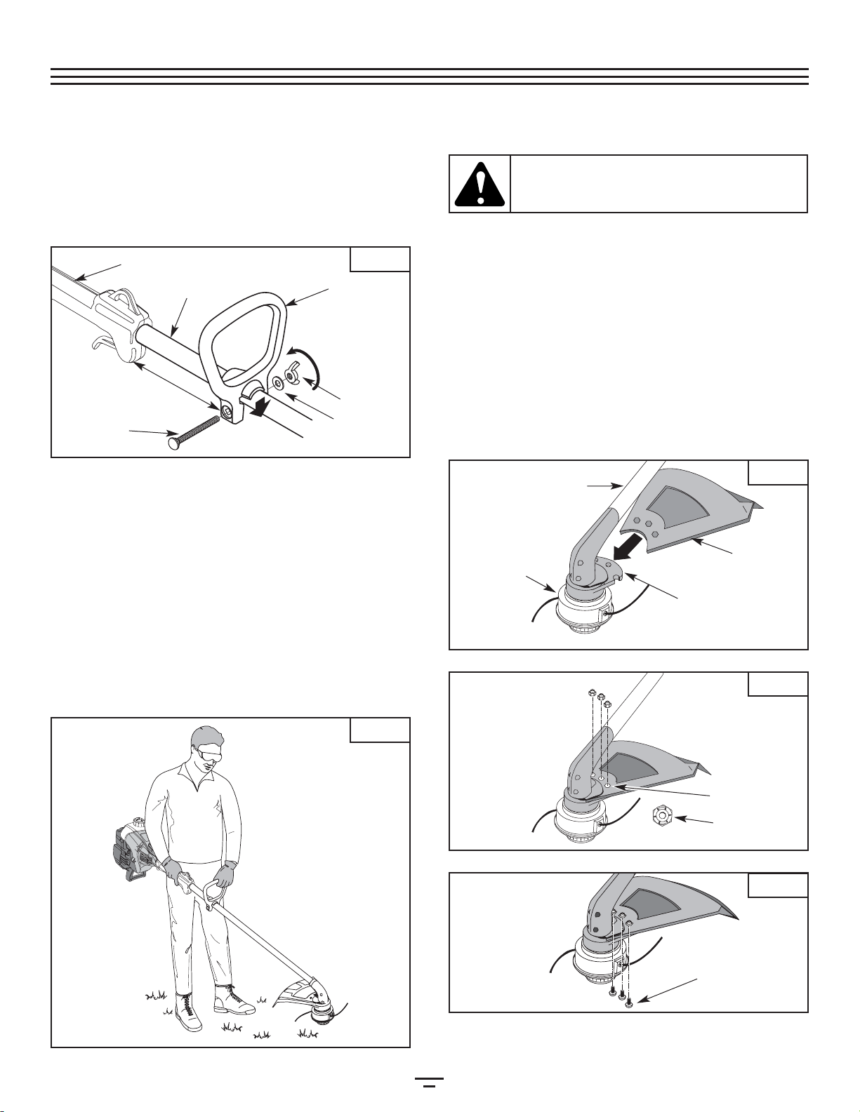
•Inspect the unit before use. Replace damaged parts. Check
for fuel leaks. Make sure all fasteners are in place and
secure. Replace cutting attachment parts that are cracked,
chipped or damaged in any way. Make sure the cutting
attachment is properly installed and securely fastened. Be
sure that the cutting attachment shield is properly
attached, and positioned as recommended. Failure to do so
can result in personal injury to the operator and
bystanders,as well as damage to the unit.
•Use only a 0.080-inch (2.03 mm) diameter Genuine Factory
Parts™ replacement line. Never use metal-reinforced line,
wire, chain or rope. These can break off and become dan-
gerousprojectiles.
•Beaware of risk of injury to the head, hands and feet.
WARNING:
When using the unit, you must follow
the safety rules. Please read these instructions
before operating the unit in order to ensure the
safety of the operator and any bystanders. Please
keepthese instructions for later use.
•Squeeze the throttle control and check that it returns auto-
matically to the idle position. Make all adjustments or
repairsbefore using the unit.
•Clear the area to be cut before each use. Remove rocks,
broken glass, nails, wire, string and other objects which
may be thrown or become entangled in the cutting attach-
ment. Clear the area of children, bystanders and pets; keep
them outside a 50-foot (15 m.) radius, at a minimum. Even
then, they are still at risk from thrown objects. Encourage
bystanders to wear eye protection. If you are approached,
stopthe unit immediately.
•This unit was not designed to be used as a brushcutter. Do
not attach or operate this unit with any type of brushcut-
tingblade or brushcutting attachment.
SAFETYWARNINGS FOR GAS TRIMMERS
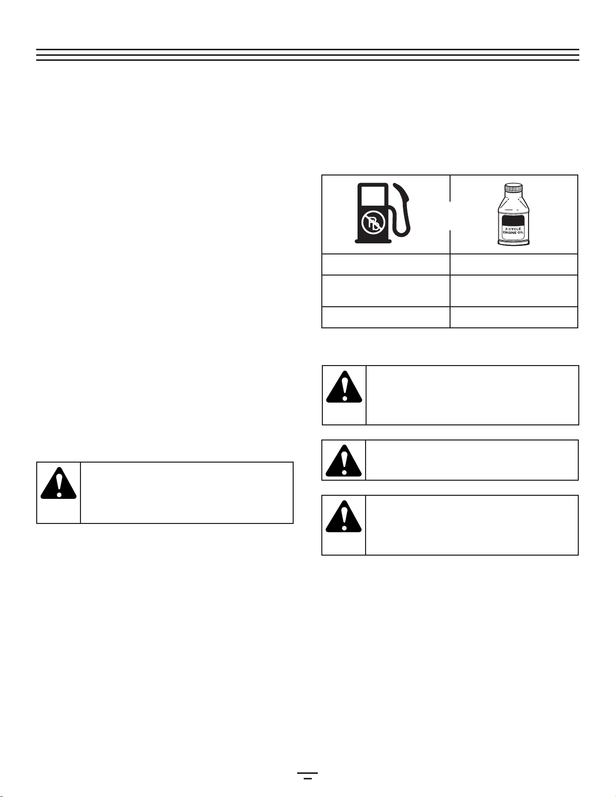
•Store fuel only in containers specifically designed and
approvedfor the storage of such materials.
•Always stop the engine and allow it to cool before filling
the fuel tank. Never remove the fuel tank cap or add fuel
when the engine is hot. Never operate the unit without the
fuel cap securely in place. Loosen the fuel tank cap slowly
torelieve any pressure in the tank.
WARNING: Gasoline is highly flammable and its
vapors can explode if ignited. Follow the ensu-
ingprecautions.
RULESFORSAFEOPERATION
NOTE: For users on U.S. Forest Land and in the states of California, Maine, Oregon, and Washington. All U.S. Forest Land and
the state of California (Public Resources Codes 4442 and 4443), Oregon, and Washington require by law that certain internal com-
bustion engines operated on forest brush and/or grass-covered areas be equipped with a spark arrestor, maintained in effective
working order, or the engine be constructed, equipped, and maintained for the prevention of fire. Check with your state or local
authorities for regulations pertaining to these requirements. Failure to follow these requirements could subject you to liability or a
fine. This unit is factory equipped with a spark arrestor. If it requires replacement, ask your LOCAL SERVICE DEALER to install
theAccessory Part #182747 Spark Arrestor.
Read the Operator’s Manual(s) and follow all warnings and safety instructions.
Failure to do so can result in serious injury to the operator and/or bystanders.
FOR QUESTIONS,CALL 1-330-558-7720 or 1-866-840-6483
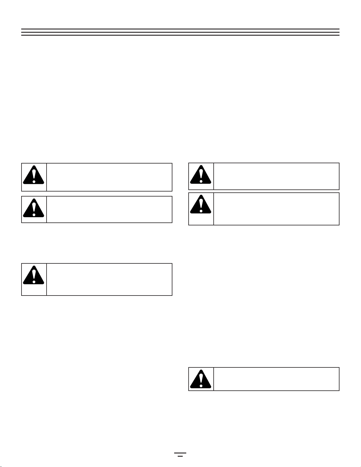
SAFETY ALERT SYMBOL
:Indicates danger, warn-
ing or caution. Attention is required in order to
avoid serious personal injury. May be used in
conjunctionwith other symbols or pictographs.
• SAFETY SYMBOLS •
• IMPORTANT SAFETY INFORMATION •
READ ALL INSTRUCTIONS
The purpose of safety symbols is to attract your attention to possible dangers. The safety symbols, and their explanations, deserve
your careful attention and understanding. The safety warnings do not by themselves eliminate any danger. The instructions or
warningsthey give are not substitutes for proper accident prevention measures.
SYMBOL MEANING
DANGER: Failure to obey a safety warning will
result in serious injury to yourself or to others.
Always follow the safety precautions to reduce
therisk of fire, electric shock and personal injury.
WARNING: Failure to obey a safety warning can
result in injury to yourself and others. Always fol-
low the safety precautions to reduce the risk of
fire,electric shock, and personal injury.
CAUTION: Failure to obey a safety warning may
result in property damage or personal injury to
yourself or to others. Always follow the safety
precautions to reduce the risk of fire, electric
shock,and personal injury.
SYMBOL MEANING
NOTE: Advises you of information or instructions vital to the operation or maintenance of the equipment.

4
• IMPORTANT SAFETY INFORMATION •
•Add fuel in a clean, well-ventilated outdoor area where
there are no sparks or flames. Remove the fuel cap slowly,
and only after the engine stops. Do not smoke while fuel-
ing or mixing fuel. Wipe up any spilled fuel from the unit
immediately.
•Avoid creating a source of ignition for spilled fuel. Do not
startthe engine until fuel vapors dissipate.
•Move the unit at least 30 feet (9.1 m) from the fueling
source and site before starting the engine. Do not smoke.
Keep sparks and open flames away from the area while
addingfuel or operating the unit.
WHILE OPERATING
•Never start or run the unit inside a closed room or building.
Breathing exhaust fumes can be fatal. Operate this unit
onlyin a well-ventilated outdoor area.
•Wear safety glasses or goggles that meet ANSI Z87.1 stan-
dards and are marked as such. Wear ear/hearing protection
when operating this unit. Wear a face or dust mask if the
operationis dusty.
•Wear heavy long pants, boots, gloves and a long sleeve
shirt. Do not wear loose clothing, jewelry, short pants, san-
dalsor go barefoot. Secure hair above shoulder level.
•The cutting attachment shield must always be in place while
operating the unit. Do not operate unit without both trim-
ming lines extended, and the proper line installed. Do not
extendthe trimming line beyond the length of the shield.
•This unit does not have a clutch. The cutting attachment
continuesrotating when the engine is idling.
•Adjust the D-handle to your size in order to provide the
bestgrip.
•Be sure the cutting attachment is not in contact with any-
thingbefore starting the unit.
•Usethe unit only in daylight or good artificial light.
•Avoid accidental starting. Be in the starting position when-
ever pulling the starter rope. The operator and unit must
be in a stable position while starting. Refer to the
Starting/StoppingInstructions.
•Usethe right tool. Only use this tool for its intended purpose.
•Donot overreach. Always keep proper footing and balance.
•Always hold the unit with both hands when operating.
Keepa firm grip on both handles or grips.
•Keep hands, face, and feet at a distance from all moving
parts. Do not touch or try to stop the cutting attachment
whenit rotates.
•Do not touch the engine, gear housing or muffler. These
parts get extremely hot from operation, even after the unit
isturned off.
•Do not operate the engine faster than the speed needed to
cut, trim or edge. Do not run the engine at high speed
whennot cutting.
•Always stop the engine when cutting is delayed or when
walkingfrom one cutting location to another.
•If you strike or become entangled with a foreign object,
stop the engine immediately and check for damage. Do
not operate before repairing damage. Do not operate the
unitwith loose or damaged parts.
•Stop the unit, switch the engine to off, and disconnect the
sparkplug for maintenance or repair.
•Use only Genuine Factory Parts™ replacement parts and
accessories for this unit. These are available from your
authorized service dealer. Use of any unauthorized parts or
accessories could lead to serious injury to the user, or dam-
ageto the unit, and void your warranty.
•Keep unit clean of vegetation and other materials. They
may become lodged between the cutting attachment and
shield.
•To reduce fire hazard, replace a faulty muffler and spark
arrestor. Keep the engine and muffler free from grass,
leaves,excessive grease or carbon build up.
OTHER SAFETYWARNINGS
•Never store a fueled unit inside a building where fumes
mayreach an open flame or spark.
•Allow the engine to cool before storing or transporting. Be
sureto secure the unit while transporting.
•Store the unit in a dry area, locked up or up high to prevent
unauthorizeduse or damage, out of the reach of children.
•Never douse or squirt the unit with water or any other liq-
uid. Keep handles dry, clean and free from debris. Clean
after each use, see CleaningandStorage instructions.
•Keep these instructions. Refer to them often and use them
to instruct other users. If you loan someone this unit, also
loanthem these instructions.
SAVETHESE INSTRUCTIONS
RULESFORSAFEOPERATION

5
SYMBOL MEANING
•THROWN OBJECTS AND ROTATING
CUTTER CAN CAUSE SEVERE
INJURY
WARNING: Donot operate without the
cuttingattachment shield in place.
Keepaway from the rotating cutting
attachment.
•HOT SURFACEWARNING
Donot touch a hot muffler, gear housing
orcylinder. You may get burned. These
partsget extremely hot from operation.
Theyremain hot for a short time after the
unitis turned off.
•SHARP BLADE
WARNING: Sharpblade on cutting
attachmentshield. To prevent serious
injury,do not touch line cutting blade.
•CHOKE CONTROL
A • FULL chokeposition.
B • PARTIAL chokeposition.
C • RUN position.
•ON/OFF STOP CONTROL
ON/ START / RUN
•ON/OFF STOP CONTROL
OFFor STOP
SYMBOL MEANING
•SAFETY ALERT SYMBOL
Indicatesdanger, warning or caution.
Maybe used in conjunction with other
symbolsor pictographs.
•WARNING - READ OPERATOR'S
MANUAL
Readthe operator’s manual(s) and follow
allwarnings and safety instructions.
Failureto do so can result in serious
injuryto the operator and/or bystanders.
•WEAR EYE AND HEARING
PROTECTION
WARNING: Thrownobjects and loud
noisecan cause severe eye injury and
hearingloss. Wear eye protection
meetingANSI Z87.1 standards and ear
protectionwhen operating this unit. Use
afull face shield when needed.
•KEEP BYSTANDERS AWAY
WARNING: Keepall bystanders,
especiallychildren and pets, at least 50
feet(15 m) from the operating area.
•UNLEADED FUEL
Alwaysuse clean, fresh unleaded fuel.
•OIL
Referto operator's manual for the proper
typeof oil.
SAFETY AND INTERNATIONAL SYMBOLS
Thisoperator's manual describes safety and international symbols and pictographs that may appear on this product.
Readthe operator's manual for complete safety, assembly, operating and maintenance and repair information.
RULESFORSAFEOPERATION

6
APPLICATIONS
Asa trimmer:
•Cuttinggrass and light weeds
•Edging
•Decorativetrimming around trees, fences, etc.
KNOWYOUR UNIT
RULESFORSAFEOPERATION
Fuel Cap
Throttle
Control
D-Handle
Shaft
Grip
Primer
Bulb
Choke
Lever
Air Filter/Muffler
Cover
Spark Plug
Shaft
Tube
Starter
Rope Grip
Line Cutting Blade
Muffler
On/Off Stop
Control
Cutting
Attachment Cutting Attachment Shield

7
Onsome units, the handle may be pre-installed. In this case
youmust loosen hardware and adjust the handle to fit the
operator.Go to step 3 if the D-handle is pre-installed.
INSTALL AND ADJUSTTHE D-HANDLE
1. Pushthe D-handle down onto the shaft housing so that
thehandle slants towards the shaft grip (Fig. 1). The
squaredbolt hole in the handle is to the right.
2. Insertthe shoulder bolt into the squared hole in the
handleand push through. On the left side of the handle,
placethe washer on the bolt, then screw the wing nut
ontothe bolt. Do not tighten until you make the handle
adjustment.
3. Ifthe D-handle was pre-installed, loosen the wing nut on
itjust enough so the handle can freely move. Rotate the
D-handleto place the grip above the top of the shaft
housing.Place it a minimum of 6 inches (15.24 cm) from
theend of the shaft grip.
4. While holding the unit in the operating position (Fig. 2),
positionthe D-handle to the location that provides you
thebest grip.
5. Tightenthe wing nut until the D-handle is secure.
ASSEMBLYINSTRUCTIONS
Fig.1
Fig.2
Bolt Washer
Wing Nut
Tighten
Shaft Grip
D-Handle
Minimum 6 inches
(15.24 cm)
Shaft Housing
INSTALLINGTHE CUTTING SHIELD
Usethe following instructions if the cutting attachment shield
onyour unit is not installed or if you ever need to re-install it.
1. Slidethe cutting attachment shield into the shield mount
onthe cutting attachment. Align the screw holes in the
shieldwith the holes in the cutting attachment shield
mount(Fig. 3).
2. Placeone of the three (3) supplied hex lock nuts into one
ofthe three recessed holes on the top of the cutting
attachmentshield (Fig 4).
3. Installascrewintothehole from the bottomofthecutting
attachmentshield.Screwitintothe nut installed instep2
untilitisstarted(Fig5). Do not tighten.
4. Repeatsteps 2 and 3 until all three screws have been
started.Then tighten all screws securely with a Phillips
headscrewdriver.
WARNING: To prevent serious personal injury,
never operate the trimmer without the cutting
attachmentshield in place.
Recessed Holes
Shaft Housing
Shield
Mount
Cutting
Attachment
Shield
Cutting
Attachment
(3) Screws
Hex Lock Nut
Fig.3
Fig.4
Fig.5

8
NOTE: Dispose of the old fuel/oil mix in accordance to
Federal,State and Local regulations.
CAUTION: Forproper engine operation and max-
imum reliability, pay strict attention to the oil and
fuel mixing instructions on the 2-cycle oil con-
tainer. Using improperly mixed fuel can severely
damagetheengine.
WARNING: Gasoline is extremely flammable.
Ignited Vapors may explode. Always stop the
engine and allow it to cool before filling the fuel
tank. Do not smoke while filling the tank. Keep
sparksand open flames at a distance from the area.
WARNING: Remove fuel cap slowly to avoid injury
from fuel spray. Never operate the unit without the
fuelcap securely in place
.
WARNING: Add fuel in a clean, well ventilated
area outdoors. Wipe up any spilled fuel immedi-
ately. Avoid creating a source of ignition for spilt
fuel. Do not start the engine until fuel vapors
dissipate.
OIL AND FUEL MIXING INSTRUCTIONS
Oldand/or improperly mixed fuel are the main reasons for
improperunit performance. Be sure to use fresh, clean
unleadedfuel. Follow the instructions carefully for the proper
fuel/oilmixture.
Definition of Blended Fuels
Today'sfuels are often a blend of gasoline and oxygenates
suchas ethanol, methanol, or MTBE (ether). Alcohol-blended
fuelabsorbs water. As little as 1% water in the fuel can make
fueland oil separate. It forms acids when stored. When using
alcohol-blendedfuel, use fresh fuel (less than 60 days old).
Using Blended Fuels
Ifyou choose to use a blended fuel, or its use is unavoidable,
followrecommended precautions:
•Alwaysuse the fresh fuel mix explained in your opera-
tor'smanual
•Alwaysagitate the fuel mix before fueling the unit
•Drainthe tank and run the engine dry before storing the
unit
Using Fuel Additives
Thebottle of 2-cycle oil that came with your unit contains a
fueladditive which will help inhibit corrosion and minimize
theformation of gum deposits. It is recommended that you
useour 2-cycle oil with this unit.
Ifunavailable, use a good 2-cycle oil designed for air-cooled
enginesalong with a fuel additive, such as STA-BIL® Gas
Stabilizeror an equivalent. Add 0.8 oz. (23 ml.) of fuel
additiveper gallon of fuel according to the instructions on
thecontainer. NEVER add fuel additives directly to the unit's
fueltank.
Thoroughlymix the proper ratio of 2-cycle engine oil with
unleadedgasoline in a separate fuel can. Use a 32:1 fuel/oil
ratio.Do not mix them directly in the engine fuel tank. See
thetable below for specific gas and oil mixing ratios.
NOTE: One gallon (3.8 liters) of unleaded gasoline
mixed with one 4 oz. (120 ml.) bottle of
2-cycleoil makes a 32:1 fuel/oil ratio.
OIL&FUELINFORMATION
UNLEADED GAS 2 CYCLE OIL
1 US. GALLON
(3.8 LITERS) 4 FL OZs.
(118 ml)
1 LITER 31 ml
+
MIXING RATIO = 32 : 1

9
STARTING INSTRUCTIONS
1. Mixgas with oil. Fill fuel tank with fuel/oil mixture. Refer
toOilandFuelMixingInstructions.
2. Make sure the On/Off Stop Control in the ON (I)position
(Fig. 6).
3. Fullypress and release the primer bulb 10 times, slowly,
until FUEL IS VISIBLE IN THE PRIMER BULB (Fig. 7). If
youcan’t see fuel in the bulb, press and release the bulb
three(3) additional times, or as many times as it takes
beforeyou can see fuel in it.
4. Place the choke lever in the FULL choke(A) position
(Fig.7).
5. Withthe unit in the starting position (Fig. 8), squeeze the
throttlecontrol to the wide open (full throttle) position.
Pull the starter rope briskly 5 times in the FULL choke
(A) position.If the engine attempts to run before the
fifthpull, proceed to step 6.
NOTE: The engine will not run in the FULL choke (A)
position.
6. Place the choke lever in the PARTIAL choke(B)
position(Fig. 7).
7. Pullstarter rope briskly 1 to 3 times to start the engine
(Fig.8).
NOTE: Squeeze the throttle control until the engine has
startedand warmed up.
8. Ifthe engine does not start, repeat steps 4 through 7.
9. Squeezethe throttle control to warm up the engine for 5
to 10 seconds. Place the choke lever in the RUN (C)
position(Fig. 7).
NOTE: Choking is unnecessary when starting a warm
engine. Start the unit in the PARTIAL choke (B)
position (Fig. 7). After starting, place the
choke lever in the RUN (C) position(Fig. 7).
WARNING:
Operate this unit only in a well- ventilat-
ed outdoor area. Carbon monoxide exhaust fumes
canbe lethal in aconfinedarea.
WARNING: Avoid accidental starting. Make sure
you are in the starting position when pulling the
starter rope (Fig. 8).
To avoid serious injury, both
the operator and unit must be in a stable position
whilestarting.
On/Off Stop
Control
Start/On (I)
Stop/Off (O)
Choke Lever
Full Choke
Position (A)
Run Position
(C)
Partial Choke
Position (B)
Starter Rope
Throttle Control
Primer Bulb
STOPPING INSTRUCTIONS
1. Releaseyour hand from the throttle control (Fig. 8). Allow
theengine to cool down by idling.
2. Putthe On/Off Stop Control in the OFF (O) position (Fig. 6).
STARTING/STOPPINGINSTRUCTIONS
Fig.8
Fig.7
Fig.6

10
HOLDINGTHETRIMMER
Beforeoperating the unit, stand in the operating position
(Fig.9). Check for the following:
•Theoperator is wearing eye protection and proper
clothing
•Witha slightly-bent right arm, the operator’s right hand
isholding the shaft grip
•Theoperator’s left arm is straight, the left hand holding
theD-handle
•Theunit is at waist level
•Thecutting attachment is parallel to the ground and
easilycontacts the grass without the need to bend over
WARNING: Always wear eye, hearing, foot and
body protection to reduce the risk of injury
whenoperating this unit.
NOTE: Do not rest the Bump Head™ on the ground
whilethe unit is running.
Someline breakage will occur from:
•Entanglementwith foreign matter
•Normalline fatigue
•Attemptingto cut thick, stalky weeds
•Forcingtheline intoobjectssuch aswallsor fenceposts
TIPS FOR BESTTRIMMING RESULTS
•Forbest trimming results, operate unit at full throttle.
•Keepthe cutting attachment parallel to the ground.
•Donot force the cutting attachment. Allow the tip of the
lineto do the cutting, especially along walls. Cutting with
morethan the tip will reduce cutting efficiency and may
overloadthe engine.
•Cutgrass over 8 inches (200 mm) by working from top to
bottomin small increments to avoid premature line wear
orengine drag.
•Cutfrom left to right whenever possible. Cutting to the
rightimproves the unit's cutting efficiency. Clippings are
thrownaway from the operator.
•Slowlymove the trimmer into and out of the cutting area
atthe desired height. Move either in a forward-backward
orside-to-side motion. Cutting shorter lengths produces
thebest results.
•Trimonly when grass and weeds are dry.
•Thelife of your cutting line is dependent upon:
•Properadherence of trimming techniques (explained above)
•Whatvegetation is cut
•Wherevegetation is cut
Forexample,thelinewillwearfasterwhentrimmingagainsta
foundationwallasopposedtotrimmingaroundatree.
CAUTION:
Do not remove or alter the line cutting
blade assembly. Excessive line length will make the
clutch overheat. This may lead to serious personal
injuryordamage totheunit.
OPERATINGINSTRUCTIONS
Fig.9
ADJUSTINGTRIMMING LINE LENGTH
TheBumpHead™cuttingattachmentallows you to release
trimminglinewithoutstoppingtheengine. To release more
line,lightlytapthecuttingattachment on the ground(Fig.10)
whileoperatingthetrimmerathigh speed.
NOTE:Always keep the trimming line fully extended.
Line release becomes more difficult as cutting
linebecomes shorter
Eachtime the head is bumped, about 1 inch (25.4 mm) of
trimmingline releases. A blade in the cutting attachment
shieldwill cut the line to the proper length if any excess line
isreleased.
Forbest results, tap the bump knob on bare ground or hard soil.
Ifyou attempt a line release in tall grass, the engine may stall.
Alwayskeep the trimming line fully extended. Line release
becomesmore difficult when the cutting line gets shorter.
DECORATIVETRIMMING
Decorativetrimming is accomplished by removing all
vegetationaround trees, posts, fences, etc.
Rotatethe whole unit so that the cutting attachment is at a
30°angle to the ground (Fig. 11).
Fig.10
Fig.11

11
MAINTENANCE SCHEDULE
Performthese requiredmaintenance proceduresat the
frequencystated inthe table.These procedures should also
bea partof anyseasonal tune-up.
NOTE: Some maintenance procedures may require
special tools or skills. If you are unsure about
these procedures take your unit to any non-
road engine repair establishment, individual or
authorizedservice dealer.
NOTE: Maintenance, replacement, or repair of the emis-
sion control devices and system may be per-
formed by any non-road engine repair establish-
ment,individual or authorized service dealer.
Inorder to assure peak performance of your engine,
inspectionof the engine exhaust port may be necessary after
50hours of operation. If you notice lost RPM, poor
performanceor general lack of acceleration, this service may
berequired. If you feel your engine is in need of this
inspection,refer service to any non-road engine repair
establishment,individual or authorized service dealer for
repair.DO NOT attempt to perform this process yourself as
enginedamage may result from contaminants involved in
thecleaning process for the port.
FREQUENCY MAINTENANCE REQUIRED REFER TO
Beforestarting engine Fill fuel tank with fresh fuel Page8
Every10 hours Clean and re-oil air filter Page13
Every25 hours Check and clean spark arrestor
Checkspark plug condition and gap Page 14
Page15
Every50 hours Inspect exhaust port and spark arrestor screen for clogging or
obstructionto assure maximum performance levels Page 14
WARNING: To prevent serious injury, never per-
form maintenance or repairs with unit running.
Always service and repair a cool unit. Disconnect
the spark plug wire to ensure that the unit can-
notstart.
Indexing Teeth
MAINTENANCE& REPAIRINSTRUCTIONS
Fig.14
LINE INSTALLATION
Thissection covers both SplitLine™ and standard single line
installation.
Always use Genuine Factory Parts™ 0.080 in. (2.03 mm)
replacementline. Using line other than the specified may
makethe engine overheat or fail.
Thereare two methods to replace the trimming line:
•Wind the inner reel with new line
•Install a prewound inner reel
Winding the Existing Inner Reel
1. Holdthe outer spool with one hand and unscrew the
bumpknob counterclockwise (Fig. 12). Inspect the bolt
insidethe bump knob to make sure it moves freely.
Replacethe bump knob if damaged.
Bump Knob
Bolt
WARNING: Never use metal-reinforced line,
wire, chain or rope. These can break off and
becomedangerous projectiles.
Fig.12
Inner Reel
Spring
Outer Spool
Fig.13
2. Removethe inner reel from the outer spool (Fig. 13).
3. Removespring from the inner reel (Fig. 13).
4. Usea clean cloth to clean the inner reel, spring, shaft, and
innersurface of the outer spool.
5. Checkthe indexing teeth on the inner reel and outer
spoolfor wear (Fig. 14). If necessary, remove burrs or
replacethe reel and spool.

Loop
Fig.16
12
NOTE: SplitLine™ can only be used with the inner reel
with the slotted holes. Single line can be used
on either type of inner reel. Use Figure 15 to
identifythe inner reel you have.
NOTE: Always use the correct line length when installing
trimming line on the unit. The line may not
releaseproperlyif thelineis toolong.
Single Line Installation
GoToStep8forSplitLine™Installation
6. Takeapproximately 40 feet (12.2 m) of new trimming
line,loop it into two equal lengths. Insert each end of the
linethrough one of the two holes in the inner reel
(Fig. 16). Pull the line through the inner reel so that the
loopis as small as possible.
7. Windthe lines in tight even layers, onto the reel (Fig. 17).
Windthe line in the direction indicated on the inner reel.
Placeyour index finger between the two lines to stop the
linesfrom overlapping. Do not overlap the ends of the
line.Proceed to step 11.
SplitLine™ Installation
8. Takeapproximately 20 feet (6.1 m) of new trimming line.
Insertone end of the line through one of the two holes in
theinner reel (Fig. 18). Pull the line through the inner reel
untilonly about 4 inches is left out.
9. Insertthe end of the line into the open hole in the inner
reeland pull the line tight to make the loop as small as
possible(Fig. 18).
10. Beforewinding, split the line back about 6 inches.
11. Windthe line in tight even layers in the direction
indicatedon the inner reel.
NOTE:
Failure to wind the line in the direction indicated will
causethe cutting attachment tooperateincorrectly.
Loop
Slotted Holes
For Use with SplitLine™ or
Single Line
For Use with Single
Line ONLY
Holding Slots
NOTE: The spring must be assembled on the inner reel
beforereassembling the cutting attachment.
14. Holdthe inner reel in place and install the bump knob by
turningclockwise. Tighten securely.
1
2. Insertthe ends of the line into the two holding slots (Fig. 19).
13. Insertthe ends of the line through the eyelets in the
outerspool and place inner reel with spring inside the
outerspool (Fig. 20). Push the inner reel and outer spool
together.While holding the inner reel and outer spool,
graspthe ends and pull firmly to release the line from the
holdingslots in the reel.
MAINTENANCE& REPAIRINSTRUCTIONS
Fig.20
Fig.19
Fig.18
Fig.17
Fig.15
Spring
Eyelet
Eyelet

13
AIR FILTER MAINTENANCE
Removing the Air Filter/Muffler Cover
1. Place the choke lever in the PARTIAL chokeposition (B).
NOTE: The choke lever must be in the PARTIAL choke
position (B) (Fig. 21) to remove the air filter/muf-
flercover.
2. Removethe four (4) screws securing the air filter/muffler
cover(Fig. 21). Use a flat blade or T20 Torx bit
screwdriver.
3. Pullthe cover from the engine. Do not force.
Choke Lever
Screws Screws
Partial Choke
Position (B)
INSTALLING A PREWOUND REEL
1. Holdthe outer spool withonehandandunscrewthebump
knobcounterclockwise (Fig. 12). Inspecttheboltinsidethe
bumpknob to make sureitmovesfreely.Replacethebump
knobif damaged.
2. Removethe old inner reel from the outer spool (Fig. 13).
3. Removethe spring from the old inner reel (Fig. 13).
4. Placethe spring in the new inner reel.
NOTE: The spring must be assembled on the inner reel
beforereassembling the cutting attachment.
5. Insertthe ends of the line through the eyelets in the
outerspool (Fig. 20).
6. Placethe new inner reelinsidetheouterspool.Pushthe
innerreel and outer spooltogether.Whileholdingtheinner
reeland outer spool, grasptheendsandpullfirmlyto
releasethe line from theholdingslotsinthespool.
7. Holdthe inner reel in place and install the bump knob by
turningclockwise. Tighten securely.
Replacement Parts
See Accessories/ReplacementParts.
WARNING: To avoid serious personal injury,
always turn your trimmer off and allow it to cool
beforeyou clean or serviceit.
Cleaning the Air Filter
Cleanand re-oil the air filter every 10 hours of operation. It is
animportant item to maintain. Failure to maintain the air
filterwill VOID the warranty.
1. Remove air filter/muffler cover. Refer to RemovingtheAir
Filter/MufflerCover.
2. Turncover over and look inside to locate the air filter.
Removethe air filter from inside the air filter/muffler
cover(Fig. 22).
3. Washthe filter in detergent and water (Fig. 22). Rinse the
filterthoroughly. Squeeze out excess water. Allow it to
drycompletely.
4. Applyenough clean SAE 30 oil to lightly coat the filter
(Fig.23).
5. Squeezethe filter to spread and remove excess oil (Fig. 23).
6. Replacethe air filter inside the air filter/muffler cover
(Fig.22).
NOTE: Operating the unit without the air filter and air fil-
ter/mufflercover assembly will VOIDthewarranty.
MAINTENANCE& REPAIRINSTRUCTIONS
Fig.21
Air Filter
Inside Muffler
Cover
Fig.23
Fig.22

14
Reinstalling the Air Filter/Muffler Cover
1. Placethe air filter/muffler cover over the back of the
carburetorand muffler. Align the screw holes.
2. Insertthe four (4) screws into the holes in the air
filter/mufflercover (Fig. 21) and tighten.
Do not over tighten.
SPARK ARRESTOR MAINTENANCE
1. Remove air filter/muffler cover. Refer to RemovingtheAir
Filter/MufflerCover.
2. Locatemuffler front and the two (2) bolts securing it to
theengine (Fig. 24). Remove the two (2) bolts using a
flatbladescrewdriver or 5/16-inch socket or nut driver.
Pullmuffler off of the engine.
3. Turnmuffler over to the back side and locate the exhaust
gasket.Remove the muffler gasket from the muffler (Fig. 24).
NOTE: If the exhaust gasket is torn or damaged, replace
itwitha newgasketbefore reassemblingmuffler.
4. Usinga small flatblade screwdriver, carefully pry up the
sparkarrestor from the recessed hole (Fig. 25). Remove
thespark arrestor from the muffler.
5. Cleanthe spark arrestor with a wire brush. Replace it if it is
damaged or if it is impossible to clean thoroughly (Fig. 25).
6. Reinstallthe spark arrestor by pressing it into the
recessedhole on the muffler's back side. Make sure it fits
tightlyagainst the muffler and is not raised up.
7. Placethe exhaust gasket against muffler's back side.
Alignthe gasket bolt holes with the bolt holes in the
muffler.While holding exhaust gasket in place, insert the
boltsinto the muffler's front side (Fig. 24).
8. Placethe muffler (with the exhaust gasket in place and
boltsinserted), against the engine, aligning the bolt
holes.Tighten the bolts to secure the muffler to the
engine.
Ifusing a torque wrench, torque to:
80-90 in.•lb. (9-10.2 N•m)
9. Reinstallthe air filter/muffler cover.
Muffler - Front Side Muffler - Back Side
Bolts Exhaust
Gasket
Spark
Arrestor
Muffler - Back Side
Spark
Arrestor Flatblade
Screwdriver
Spark Arrestor
WARNING:
If the muffler is not tightened secure-
ly, it could fall off causing damage to the unit and
possibleserious personal injury
MAINTENANCE& REPAIRINSTRUCTIONS
Fig.25
Fig.24

15
Check Fuel Mixture
Oldand/or improperly mixed fuel is usually the reason for
improperunit performance. Drain and refill the tank with
fresh,properly-mixed fuel prior to making any adjustments.
Refer to OilandFuelInformation.
Clean Air Filter
Thecondition of the air filter is important to the operation of
theunit. A dirty air filter will restrict air flow and change the
air/fuelmixture. This is often mistaken for an out of
adjustmentcarburetor. Check the condition of the air filter
before adjusting the idle speed screw. Refer to AirFilter
Maintenance.
Adjust Idle Speed Screw
If,after checking the fuel mixture and cleaning the air filter,
theengine still will not idle, adjust the idle speed screw as
follows:
1. Startthe engine and let it run at a high idle for a minute
towarm up. Refer to Starting/StoppingInstructions.
2. Releasethe throttletrigger andlet the engine idle. If the
enginestops, inserta smallphillips or flat blade
screwdriverinto thehole inthe air filter/muffler cover
(Fig.26). Turnthe idlespeed screw in, clockwise, 1/8 of a
turnat atime (asneeded) until the engine idles smoothly.
CARBURETOR ADJUSTMENT
Theidle speed of the engine is adjustable through the air
filter/mufflercover (Fig. 26).
NOTE: Careless adjustments can seriously damage
your unit. An authorized service dealer should
makecarburetor adjustments.
Idle Speed Screw
3. Ifthe engine appears to be idling too fast, turn the idle
speed screw counterclockwise 1/8 of a turn at a time (as
needed),to reduce idle speed.
Checkingthe fuel mixture, cleaning the air filter, and
adjustingthe idle speed should solve most engine problems.
Ifnot and:
•theengine will not idle
•theengine hesitates or stalls on acceleration
•thereis a loss of engine power
Havethe carburetoradjusted byan authorized service dealer.
REPLACINGTHE SPARK PLUG
UseaChampionRDJ7Ysparkplug,orequivalent.Thecorrectair
gapis0.020inch(0.5mm).Removetheplugafterevery25
hoursofoperationandcheckitscondition.
1. Stopthe engine and allow it to cool. Grasp the plug wire
firmlyand pull it from the spark plug.
2. Cleanaround the spark plug. Remove the spark plug
fromthe cylinder head by turning a 5/8-inch socket
counterclockwise.
3. Replacea cracked, fouled or dirty spark plug. Set the air
gapat 0.020 in. (0.5 mm) using a feeler gauge (Fig. 27).
4. Installa correctly-gapped spark plug in the cylinder
head.Tighten by turning the 5/8-inch socket clockwise
untilsnug.
Ifusing a torque wrench torque to:
110-120 in.•lb. (12.3-13.5 N•m)
Do not over tighten.
0.020 in.
(0.5 mm)
CAUTION: Do not sand blast, scrape or clean
electrodes. Grit in the engine could damage the
cylinder.
WARNING: The cutting attachment may be
spinning during idle speed adjustments. Wear
protective clothing and observe all safety
instructionsto prevent serious personal injury.
WARNING: To prevent serious personal injury,
make sure the cutting attachment has stopped
rotatingbefore you turn it off and set it down.
MAINTENANCE& REPAIRINSTRUCTIONS
Fig.27
Fig.26

16
CLEANING
Use a small brush to clean off the outside of the unit. Do not
usestrong detergents. Household cleaners that contain
aromaticoils such as pine and lemon, and solvents such as
kerosene,can damage plastic housing or handle. Wipe off
anymoisture with a soft cloth.
STORAGE
•Neverstore a fueled unit where fumes may reach an
openflame or spark.
•Allowthe engine to cool before storing.
•Storethe unit locked up to prevent unauthorized use or
damage.
•Storethe unit in a dry, well-ventilated area.
•Storethe unit out of the reach of children.
LONGTERM STORAGE
Ifyou plan on storing the unit for an extended time, use the
followingstorage procedure:
1. Drainall fuel from the fuel tank into a container with the
same2-cycle fuel mixture. Do not use fuel that has been
storedfor more than 60 days. Dispose of the old fuel/oil
mixin accordance to Federal, State and Local
regulations.
2. Startthe engine and allow it to run until it stalls. This
ensuresthat all fuel has been drained from the
carburetor.
3. Allowthe engine to cool. Remove the spark plug and put
1oz. (30 ml) of any high quality motor oil or 2-cycle oil
intothe cylinder. Pull the starter rope slowly to distribute
theoil. Reinstall the spark plug.
NOTE: Remove the spark plug and drain all of the oil
from the cylinder before attempting to start the
trimmerafter storage.
4. Thoroughlyclean the unit and inspect it for any loose or
damagedparts. Repair or replace damaged parts and
tightenloose screws, nuts or bolts. The unit is ready for
storage.
TRANSPORTING
•Allowthe engine to cool before transporting.
•Drainfuel from unit.
•Tightenfuel cap before transporting.
•Securethe unit while transporting.
WARNING: To avoid serious personal injury,
always turn your trimmer off and allow it to cool
beforeyou cleanor serviceit.
ACCESSORIES/REPLACEMENT PARTS
2-Cycle Oil . . . . . . . . . . . . . . . . . . . . . . . . . . . . . . . . . . . . . . . . . 147543
Spark Plug . . . . . . . . . . . . . . . . . . . . . . . . . . . . . . . . . . . . . . . . . 610311
ExhaustGasket . . . . . . . . . . . . . . . . . . . . . . . . . . . . . . .. . .753-04159
SparkArrestor . . . . . . . . . . . . . . . . . . . . . . . . . . . . . . .. . . . . . .182747
Replacement Line . . . . . . . . . . . . . . . . . . . . . . . . . . . . . . . . . . 610375
Replacement Line Cartridge . . . . . . . . . . . . . . . . . . . . . . . . 153577
Inner Reel Spring . . . . . . . . . . . . . . . . . . . . . . . . . . . . . . . . . . . 610317
Bump Knob . . . . . . . . . .. . . . . . . . . . . . . . . . . . . . . . . . . . . . . . 153066
Fuel Cap . . . . . . . . . . . . . . . . . . . . . . . . . . . . . . . . . . . . . . . . . . . 180000
Shoulder Strap . . . . . . . . . . . . . . . . . . . . . . . . . . . . . . . . . . . . . 682075
Thesereplacement parts can be purchased from your local
authorizeddealer.
MAINTENANCE& REPAIRINSTRUCTIONS

17
If further assistance is required,contact your authorized service dealer.
CAUSE ACTION
Cuttingattachment bound with grass Stop the engine and clean cutting attachment
Cuttingattachment out of line Refill with new line
Innerreel bound up Replace the inner reel
Cuttinghead dirty Clean inner reel and outer spool
Linewelded Disassemble, remove the welded section and rewind
Linetwisted when refilled Disassemble and rewind the line
Notenough line is exposed Push the bump knob and pull out line until 4 inches
(102mm) of line is outside of the cutting attachment
CAUSE ACTION
Oldor improperly mixed fuel Drain gas tank and add fresh fuel mixture
Impropercarburetor adjustment Take to an authorized service dealer for an adjustment
Fouledspark plug Replace or clean the spark plug
Pluggedspark arrestor Clean or replace spark arrestor
CAUSE ACTION
Emptyfuel tank Fill fuel tank with properly mixed fuel
Primerbulb wasn't pressed enough Press primer bulb fully and slowly 10 times
Engineis flooded Use starting procedure with choke lever in RUN
Oldor improperly mixed fuel Drain gas tank and add fresh fuel mixture
Fouledspark plug Replace or clean the spark plug
Pluggedspark arrestor Clean or replace spark arrestor
ENGINE WILL NOT START
ENGINE WILL NOT IDLE
ENGINE WILL NOT ACCELERATE
ENGINE LACKS POWER OR STALLS WHEN CUTTING
CAUSE ACTION
Airfilter is plugged Replace or clean the air filter
Oldor improperly mixed fuel Drain gas tank and add fresh fuel mixture
Impropercarburetor adjustment Adjust according to the CarburetorAdjustmentssection
CAUSE ACTION
Oldor improperly mixed fuel Drain gas tank and add fresh fuel mixture
Impropercarburetor adjustment Take to an authorized service dealer for an adjustment
Cuttingattachment bound with grass Stop the engine and clean the cutting attachment
Dirtyair filter Clean or replace the air filter
Pluggedspark arrestor Clean or replace spark arrestor
CUTTING ATTACHMENT WILL NOT ADVANCE LINE
CAUSE ACTION
Oil,cleaner or lubricant in cutting head Clean and thoroughly dry the cutting head
CUTTING LINE ADVANCES UNCONTROLLABLY
TROUBLESHOOTING

18
EngineType...................................................................................................................................................................................... Air-Cooled,2-Cycle
Stroke................................................................................................................................................................................................. 1.25 in.(31.75 mm)
Displacement......................................................................................................................................................................................... 1.9 cu in.(31 cc)
Idle Speed RPM.................................................................................................................................................................................. 3,200 - 4,400 rpm
OperatingRPM ............................................................................................................................................................................................. 6,600+ rpm
IgnitionType...................................................................................................................................................................................................... Electronic
IgnitionSwitch..................................................................................................................................................................Momentary RockerSwitch
Spark Plug Gap.................................................................................................................................................................................. 0.020 in.(0.5 mm)
Lubrication............................................................................................................................................................................................. Fuel/Oil Mixture
Fuel/Oil Ratio................................................................................................................................................................................................................ 32:1
Carburetor............................................................................................................................................................................... Diaphragm,All-Position
Starter............................................................................................................................................................................................................ Auto Rewind
Muffler................................................................................................................................................................................................ Baffled with Guard
Throttle........................................................................................................................................................................................ Manual Spring Return
FuelTank Capacity.................................................................................................................................................................................. 13 oz.(384 ml)
ENGINE*
DRIVE SHAFT and CUTTING ATTACHMENT*
Drive Shaft Housing .......................................................................................................................................................................................Aluminum
Throttle Control................................................................................................................................................................................ Finger-TipTrigger
UnitWeight(No fuel,withcutting attachment,cutting attachment shield and D-handle).........................................10 lbs. (4.5 kg.)
Cutting Mechanism..................................................................................................................................................................................... Bump Head
LineSpool....................................................................................................................................................................................... Bump Line Releaser
Line Spool Diameter.................................................................................................................................................................... 3 inches (76.2 mm.)
Trimming Line Diameter.............................................................................................................................................................0.080 in.(2.03 mm.)
Cutting Path Diameter ..................................................................................................................................................................... 17 in.(43.18 cm.)
SPECIFICATIONS
*Allspecifications are based on the latest product information available at the time of printing. We reserve the right to make
changesat any time without notice.

19
EPA Emission ControlWarranty Statement
YourWarranty Rights and Obligations
TheEnvironmental Protection Agency and MTD SOUTHWEST INC (MTD) are pleased to explain the emission control system
warrantyon your 2002 and later small off-road engine. New small off-road engines must be designed, built and equipped to meet
stringentanti-smog standards. MTD must warrant the emission control system on your small off-road engine for the periods of
timelisted below provided there has been no abuse, neglect or improper maintenance of your small off-road engine.
Youremission control system may include parts such as the carburetor or fuel-injected system, the ignition system, and catalytic
converter.Also included may be hoses, belts, connectors and other emission-related assemblies.
Wherea warrantable condition exists, MTD will repair your small off-road engine at no cost to you including diagnosis, parts and
labor.
The2002 and later small off-road engines are warranted for two years. If any emission-related part on your engine is defective,
thepart will be repaired or replaced my MTD.
OwnersWarranty Responsibilities
•As the small off-road engine owner, you are responsible for the performance of the required maintenance listed in your
operator’smanual. MTD recommends that you retain all receipts covering maintenance on your small off-road engine, but MTD
cannotdeny warranty solely for the lack of receipts or for your failure to ensure the performance of all scheduled maintenance.
•As the small off-road engine owner, you however should be aware that MTD may deny you warranty coverage if your small off-
roadengine or a part has failed due to abuse, neglect, improper maintenance or unapproved modifications.
•You are responsible for presenting your small off-road engine to a MTD Authorized Service Center as soon as a problem exists.
Thewarranty repairs should be completed in a reasonable amount of time, not to exceed 30 days.
Ifyou have any questions regarding your warranty rights and responsibilities, you should call 1-800-345-8746.
Manufacturer’sWarranty Coverage
•The warranty period begins on the date the engine or equipment is delivered to the retail purchaser.
•The manufacturer warrants to the initial owner and each subsequent purchaser, that the engine is free from defects in material
andworkmanship which cause the failure of a warranted part for a period of two years.
•Repair or replacement of warranted part will be performed at no charge to the owner at an Authorized MTD Service Center. For
thenearest location please contact MTD at: 1-800-345-8746.
•Any warranted part which is not scheduled for replacement, as required maintenance or which is scheduled for only for regular
inspectionto the effect of “Repair or Replace as Necessary” is warranted for the warranty period. Any warranted part which is
scheduledfor replacement as required maintenance will be warranted for the period of time up to the first scheduled
replacementpoint for that part.
•The owner will not be charged for diagnostic labor which leads to the determination that a warranted part is defective, if the
diagnosticwork is performed at an Authorized MTD Service Center.
•The manufacturer is liable for damages to other engine components caused by the failure of a warranted part still under
warranty.
•Failures caused by abuse, neglect or improper maintenance are not covered under warranty.
•The use of add-on or modified parts can be grounds for disallowing a warranty claim. The manufacturer is not liable to cover
failuresof warranted parts caused by the use of add-on or modified parts.
• In order to file a claim, go to your nearest Authorized MTD Service Center. Warranty services or repairs will be provided at all
AuthorizedMTD Service Centers.
•Any manufacturer approved replacement part may be used in the performance of any warranty maintenance or repair of
emissionrelated parts and will be provided without charge to the owner. Any replacement part that is equivalent in performance
ordurability may be used in non-warranty maintenance or repair and will not reduce the warranty obligations of the
manufacturer
•The following components are included in the emission related warranty of the engine, air filter, carburetor, primer, fuel lines,
fuelpick up/ fuel filter, ignition module, spark plug and muffler.

SAVETHESE INSTRUCTIONS FOR FUTURE REFERENCE
FOR QUESTIONS CALL 1-866-840-6483
OPERATOR’S MANUAL PART NO. 769-00385 09/02
PRINTED IN U.S.A.
MANUFACTURER’S LIMITEDWARRANTYFOR:
No implied warranty, including any implied warranty of
merchantability or fitness for a particular purpose,
applies after the applicable period of express written
warranty above as to the parts as identified. No other
express warranty or guaranty, whether written or oral,
except as mentioned above, given by any person or
entity, including a dealer or retailer, with respect to any
product shall bind Troy-Bilt LLC. During the period of
the Warranty, the exclusive remedy is repair or
replacement of the product as set forth above. (Some
states do not allow limitations on how long an implied warranty
lasts,so the above limitation may not apply to you.)
The provisions as set forth in this Warranty provide the
sole and exclusive remedy arising from the sales. Troy-Bilt
LLC shall not be liable for incidental or consequential loss
or damages including, without limitation, expenses
incurred for substitute or replacement lawn care services,
for transportation or for related expenses, or for rental
expenses to temporarily replace a warranted product.
(Some states do not allow limitations on how long an implied
warrantylasts, so the above limitation may not apply to you.)
In no event shall recovery of any kind be greater than the
amount of the purchase price of the product sold.
Alteration of the safety features of the product shall void
this Warranty. You assume the risk and liability for loss,
damage, or injury to you and your property and/or to others
and their property arising out of the use or misuse or inabili-
tyto use the product.
This limited warranty shall not extend to anyone other than
the original purchaser, original lessee or the person for
whomit was purchased as a gift.
How State Law Relates to this Warranty:This warranty
gives you specific legal rights, and you may also have other
rightswhich vary from state to state.
Tolocate your nearest service dealer dial 1-866-840-6483.
TROY-BILT LLC
POBox 361131
Cleveland,OH 44136-0019U.S.A.
The limited warranty set forth below is given by Troy-Bilt
LLC with respect with new merchandise purchased and
usedin the United States, its possessions and territories.
Troy-Bilt warrants this product against defects in material
and workmanship for a period of two (2) years commencing
on the date of original purchase and will, at its option, repair
or replace, free of charge, any part found to be defective in
material or workmanship. This limited warranty shall only
apply if this product has been operated and maintained in
accordance with the Operator’s Manual furnished with the
product, and has not been subject to misuse, abuse, com-
mercial use, neglect, accident, improper maintenance, alter-
ation, vandalism, theft, fire, water or damage because of
other peril or natural disaster. Damage resulting from the
installation or use of any accessory or attachment not
approved by Troy-Bilt for use with the product(s) covered by
thismanual will void your warranty as to any resulting damage.
This warranty is limited to ninety (90) days from the date of
original retail purchase for any Bolens product that is used
for rental or commercial purposes, or any other income-pro-
ducingpurpose.
HOW TO OBTAIN SERVICE: Warranty service is available,
WITH PROOF OF PURCHASE THROUGH YOUR LOCAL
AUTHORIZED SERVICE DEALER. To locate the dealer in your
area, please check for a listing in the Yellow Pages or con-
tact the Customer Service Department of Troy-Bilt LLC by
calling 1-866-840-6483 or writing to PO Box 361131,
Cleveland, Ohio 44136-0019. No product returned directly
to the factory will be accepted unless prior written permis-
sion has been extended by the Customer Service
Departmentof Troy-Bilt LLC.
This limited warranty does not provide coverage in the
following cases:
A.Tune-ups - Spark Plugs, Carburetor Adjustments, Filters
B.Wear items - Bump Knobs, Outer Spools,CuttingLine,
InnerReels, Starter Pulley, Starter Ropes, Drive Belts
C.Troy-Bilt does not extend any warranty for products
soldor exported outside of the United States of
America,its possessions and territories, except those
soldthrough Troy-Bilt’s authorized channels of export
distribution.
Trot-Bilt reserves the right to change or improve the design of
any Bolens Product without assuming any obligation to modify
anyproduct previously manufactured.
Other manuals for BL150
2
Table of contents
Languages:
Other Bolens Trimmer manuals

Bolens
Bolens BL150 User manual

Bolens
Bolens BL100 User manual

Bolens
Bolens BL100 User manual

Bolens
Bolens TB75SS User manual

Bolens
Bolens BL110 User manual

Bolens
Bolens BL50 User manual

Bolens
Bolens BL100 User manual

Bolens
Bolens BL100 User manual

Bolens
Bolens HT816r Manual

Bolens
Bolens BL 100/ BL 150 User manual