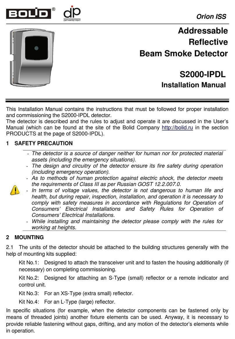
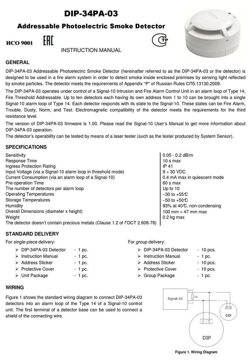
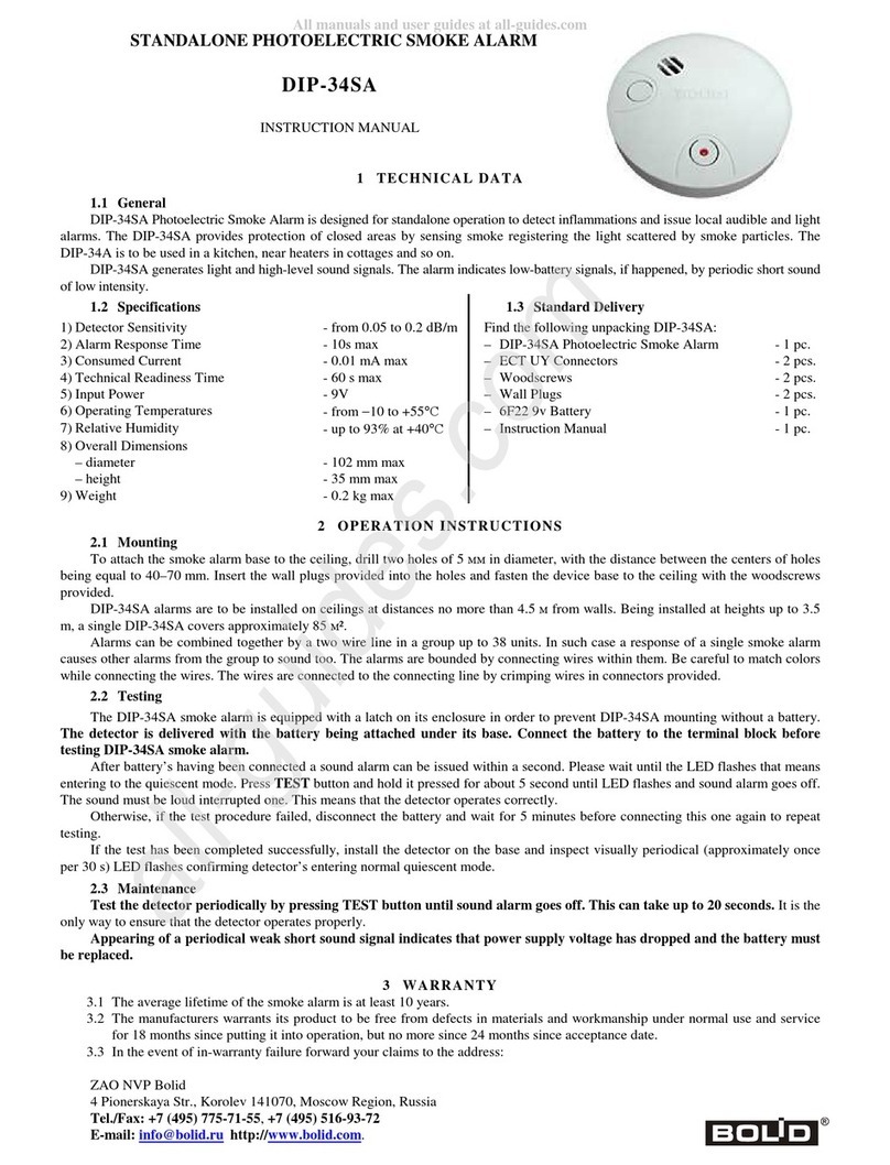
bolid DIP-34A-03 User manual

DIP-34A-03
Analog Addressable Photoelectric
Smoke Detector
INSTRUCTION MANUAL
GENERAL
DIP-34A-03 Analog Addressable Photoelectric Smoke Detector (hereinafter referred to as the DIP-34A-03 or the detector)
is to be used in a fire alarm system. It is designed to detect fires which come with appearing of smoke within closed
spaces.
The DIP-34A-03 operates under control of the S2000-KDL or S2000-KDL-2I controller which the detector is connected to
and which supplies power and communicates data with the DIP-34A-03 via the two-wire multiplex addressable polling
loop being a part of an Orion integrated security system. Up to 127 DIP-34A-03 detectors can operate under a single
S2000-KDL or S2000-KDL-2I.
The DIP-34A-03 detects smoke inside its sensing chamber by sensing light reflected by smoke particles and responds
with its state to the S2000M panel or Orion Pro software via the S2000-KDL or S2000-KDL-2I controller. Depending on
detected smoke amount these states can be Norm, Fire Prealarm or Fire Alarm.
The detector meets the requirements of Appendix “P” of Russian Regulations СП5.13130.2009.
In addition, the detector
can respond to the console’s request with a current condition of its sensing chamber which corresponds to its smoke or
dust level. Based on this answer, an operator of the control panel can make a decision about maintenance works or
waiting for a Fire Pre-alarm message in case of appearance of smoke at the beginning of a fire.
Electromagnetic compatibility of the detector meets the requirements of the third immunity level accordingly to Russian
standards.
The DIP-34A-03 supports DPLS_v2.xx Multiplex Addressable Polling Loop Protocol enabling monitoring addressable loop
voltage at the detector’s location. The version of DIP-34A-03 firmware is 1.01.
Operability of the detector can be periodically tested by means of a laser test tool (such as the test tool produced by the
System Sensor Company).
SPECIFICATIONS
Sensitivity 0.05 - 0.2 dB/m (1.2 %/m to 4.7 %/m)
Response Time 10 s max
Ingress Protection Rating IP 41
Input Voltage (from an S2000-KDL(-2I)) 8 ÷ 11 V dc
Current Consumption (via the loop of the S2000-KDL(-2I))
0.5 mA max
Pre-operation Time 60 s max
Operating Temperatures −30 to +55°C
Storage Temperatures −50 to +50°C
Humidity Up to 93% at +40°C, non-condensing
Overall Dimensions (diameter x height) 100×47 mm max
Weight 0.2 kg max
Average Lifetime At least 10 years
The content of precious materials No need to account for storage, disposal and recycling
(Clause 1.2 of Russian Standard ГОСТ 2.608-78)
STANDARD DELIVERY
For single-piece delivery: For group delivery:
DIP-34A-03 Detector - 1 pc. DIP-34A-03 Detector - 10 pcs.
Instruction Manual - 1 pc. Instruction Manual - 1 pc.
Address Sticker - 1 pc. Address Sticker - 10 pcs.
Protective Cover - 1 pc. Protective Cover - 10 pcs.
Unit Package - 1 pc. Group Package - 1 pc.
WIRING
Figure 1 shows the connection diagram for connecting a DIP-34A-03 detector to the addressable polling loop of an
S2000-KDL or S2000-KDL-2I controller. The first terminal of the mounting base can be used to connect a cable screen.

5
2
5
2
DIP-34A
S2000-KDL
-
PL
+
PL
Addressable
Device
Addressable
Device
DIP-34A
MOUNTING
When the detector is mounted on a ceiling, it is necessary to follow the requirements of Rules СП5.13130.2009, in
particular Table 13.3:
Height Average Area Monitored by a
Single Detector Distance
Between Detectors Between a Detector and Wall
Below 3.5 m Up to 85 sq.meters 9.0 meters 4.5 meters
3.5 ÷6 m Up to 70 sq.meters 8.5 meters 4.0 meters
6 ÷10 m Up to 65 sq.meters 8.0 meters 4.0 meters
10 ÷12 m Up to 55 sq.meters 7.5 meters 3.5 meters
If cannot be installed on a ceiling, the DIP-34A-03 can be mounted on wire ropes as well as on a wall, a column, or any
other structural. Installing point-type detectors on walls please follow the instructions of Appendix “П” of Rules
СП5.13130.2009.
Figure 2 shows two possible ways of attaching the detector. To attach the detector to a solid surface (variant A) use the
mounting base provided (see also the drilling pattern in Figure 3, at the left). Otherwise, a separately purchased mounting
kit MK-2 can be used to build the detector into a suspended ceiling (variant B). The size of the mounting hole is shown in
Figure 3, at the right.
Figure 3 shows the drilling pattern to install the detector for the variant A and the diameter of the mounting hole in the
suspended ceiling for the variant B.
WARNNING:
To attach the detector to the mounting base, place the detector into the base and rotate clockwise until the
detector drops into place and the matchmark moulded in the detector lines up with the short mark on the
mounting base. Continue rotating clockwise until the matchmark on the detector lines up with the matchmark 3
as shown in Figure 2 (A) and the detector locks into place.
PROGRAMMING
In order the DIP-34A-03 to operate properly within the two-wire addressable polling loop of the S2000-KDL or S2000-
KDL-2I controller, it must be assigned to a unique number from 1 to 127 within the loop – to the address which is stored in
the DIP-34A-03 non-volatile memory. This address provides identifying the detector by the controller. Moreover, a
monitoring strategy must be defined which will be used by the controller while processing signals received from the DIP-
34A-03.
Programming the DIP-34A-03 Address within the S2000-KDL/S2000-KDL-2I Addressable Loop
A DIP-34A-03 is supplied with the default address of 127. This address value can be changed using either S2000(M)
panel tools or PC tools such as UProg Configuration Tool.
Figure 3
Figure 2
1: DIP-34A-03 Smoke Detector
2:
LED Status Indicator
3: Matchmark
4: Triangular Arrow and Rectangular Hole
(open here when maintaining)
5: Mounting Base
6: MK-2 Suspended Ceiling Mounting Kit (supplied separately)
Figure 1. Connection Diagram

In order to program the unique DIP-34A-03 loop address connect the detector to a S2000-KDL/S2000-KDL-2I controller
which in turns is connected to a network controller (a S2000(M) panel or PC under UProg software). Then send one of
the following commands to the loop controller (for getting more information see the relevant User’s Manual):
Change the Device Address Use the Change Device Address command specifying the old detector address and the
new detector address as the parameters (see more information in the referred
Manuals). The network controller will display the messages about disconnecting the
device with the old address and then detecting the device with newly programmed
address.
Program the Device Address If the device address is unknown or two devices have the same address then use the
Program Device Address command specifying a required address as the parameter.
Then within 5 min press the detector light emitter or send the laser test tool beam into
it. The message about detecting the device with the newly assigned address shall be
displayed by a network controller (S2000(M)) or UProg Configuration Tool.
After programming write the set address of the detector on the “Address” label and stick it on the detector base.
Programming the S2000-KDL/S2000-KDL-2I to Operate the DIP-34A-03
To handle signals from a DIP-34A-03 correctly, an S2000-KDL/S2000-KDL-2I controller must be programmed with the
Zone Type parameter for this DIP-34A-03 being set to the value 1 (Smoke) or 8 (Smoke Analogue Addressable with
Variable Thresholds). To program the S2000-KDL/S2000-KDL-2I, connect it to a PC under UProg Configuration Tool and
follow the relevant programming instructions in accordance with the S2000-KDL/S2000-KDL-2I User’s Manual.
ROUTINE TESTING
Before testing the DIP-34A-03, please disconnect executive outputs of all system devices and modules that
can release an extinguishing agent. Notify the proper authorities that the system is undergoing maintenance.
After testing verify that all the detectors are ready to operate properly. Then restore operability of all the system
components disconnected before testing and notify the proper authorities that the system is back in operation.
All the equipment used in testing must be known functioning.
If the detector has failed please replace it for a healthy one and contact Technical Support. The
defective detector should be repaired by the manufacturer of in a certified repair center.
1. Turn on the network controller and the S2000-KDL controller. The light emitter of the detector shall light steady. When
the communications between the detector and S2000-KDL is established the light emitter will flash once per 4 seconds
indicating Norm status of the detector.
2. Take a can of test aerosol and spray some of the test material into the detector. The network controller shall display
Fire Alarm message for the device with the address of the DIP-34A-03. The detector’s LED shall flash twice every 4 s.
3. Alternately, you can perform a simplified test by pressing the detector light emitter or lighting it with the laser beam of a
laser test tool. This will cause solid lighting of the detector light emitter for 3 s followed by its double flashing every 4 s.
4. The network controller will display a:
−Fire Alarm message for the device with the address of the DIP-34A-03 if the version of the S2000-KDL in use is
1.35 or below, or
−Test message or Fire Alarm message (depending on the current test mode) when the version of the S2000-KDL
in use is 1.36 or higher (see the Manuals for the S2000-KDL controller and the network controller for more
information about testing)
5. When the test aerosol disappears (or light emitter is released, or laser test tool is disposed) the detector must be in the
Norm status. If the S2000M console or Orion Pro software has displayed no messages mentioned above or the
detector’s LED performs in a different way than mentioned above then the detector is unhealthy and must be replaced.
LED INDICATION
Flashing once per 4 s Norm
Four-time flashing once per 4 s Programming an address
Double flashing once per 4 s Fire Alarm or Test
Solid light Waiting for establishing a connection with the S2000-KDL
Pushing the LED or applying the laser test tool beam to the LED
Other Trouble

MAINTENANCE
At least annually inspect the screen assembly under the detector cover. If there is any dust on the screen assembly,
clean this one with a vacuum cleaner (by pumping air).
When a Service Required message is received from the detector, remove the dust from the sensing chamber.
In accordance with your rules of maintenance, maintain the detector as part of your fire alarm system.
WARNINGS
To avoid contamination of the detector, please DO NOT remove the protective cover until the
surrounding area is cleared from dirt and dust.
DO NOT remove the detector’s PCB because this automatically cancels the warranty.
DO NOT mount the detector within the premises where air velocity values exceed 15 m/s.
WARRANTY
The average lifetime of the detector is at least 10 years.
The manufacturer warrants its product to be free from defects in materials and workmanship under normal use and
service for 18 months since putting it into operation, but no more than 24 months since the acceptance date.
While forwarding the product for repair please apply a report describing the potential failure.
Forward your claims to the address:
ZAO NVP Bolid, 4 Pionerskaya Str., Korolev 141070, Moscow Region, Russia
Phone/fax: +7 495 775-7155 (PBX)
CONFORMITY CERTIFICATES
DIP-34A-03 Analog Addressable Photoelectric Smoke Detector is approved by Conformity Certificate
№C-RU.ЧС13.В.00149.
Conformity Certificate ТС №RU Д-RU.МЕ61.В.00312 certifies that DIP-34A-03 Analog Addressable Photoelectric Smoke
Detector meets the requirements of Technical Regulations of Custom Union TR CU 020/2011.
DIP-34A-03 is a part of Orion Addressable Fire Alarm System which is approved by Conformity Certificate
№BY/112 02.01.033 00573.
Production of DIP-34A-03 Analog Addressable Photoelectric Smoke Detector is certified in line with Russian Standard
ГОСТ ISO 9001 – 2011 by a Conformity Certificate №РОСС RU.ИК32.К00153.
PRODUCT ACCEPTANCE CERTIFICATE
DIP-34A-03 analog addressable photoelectric smoke detectors (the serial numbers are specified on the cases of the
detectors and written into the memory of their microprocessors) are qualified as proper for operation and packaged by
CJSC NVP “Bolid”.
Responsible for acceptance and packaging
QCD ________________________________________ ____________________________
Full Name Date, Month, Year
Table of contents
Other bolid Smoke Alarm manuals