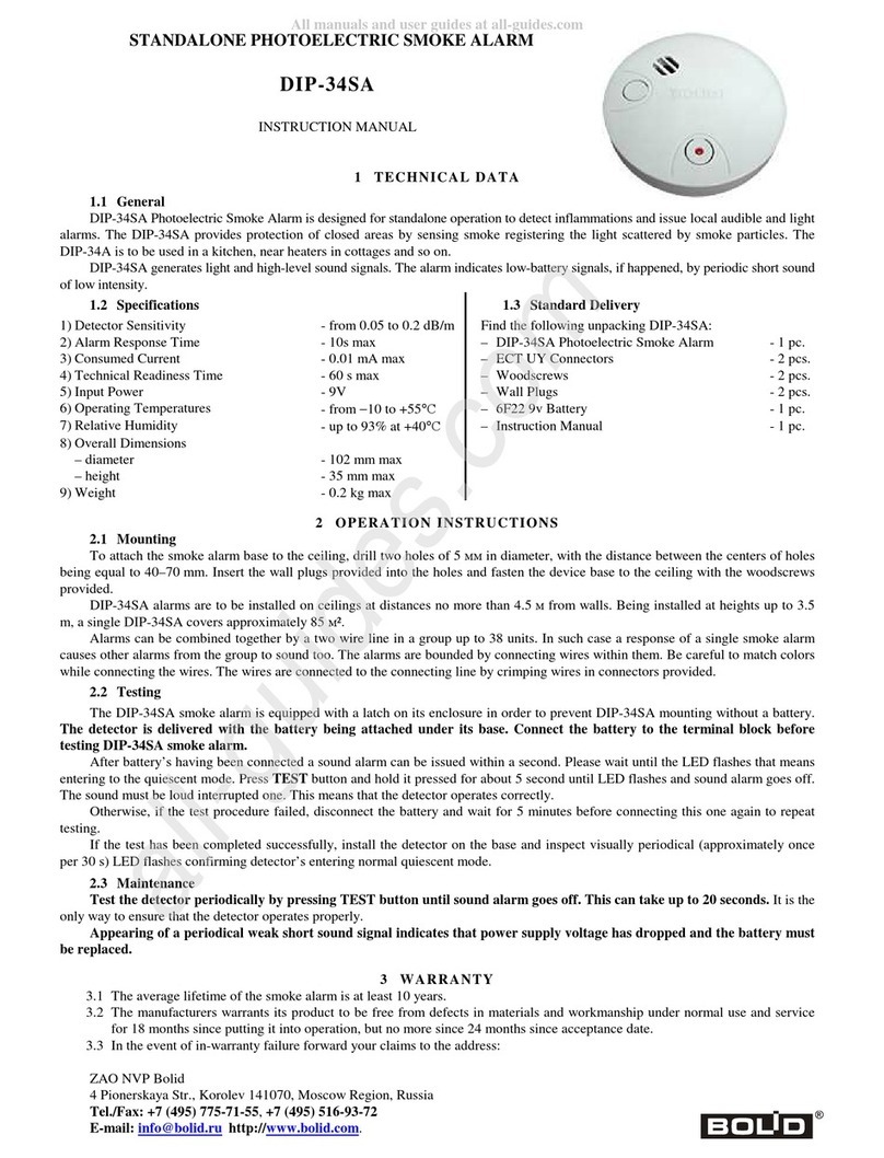
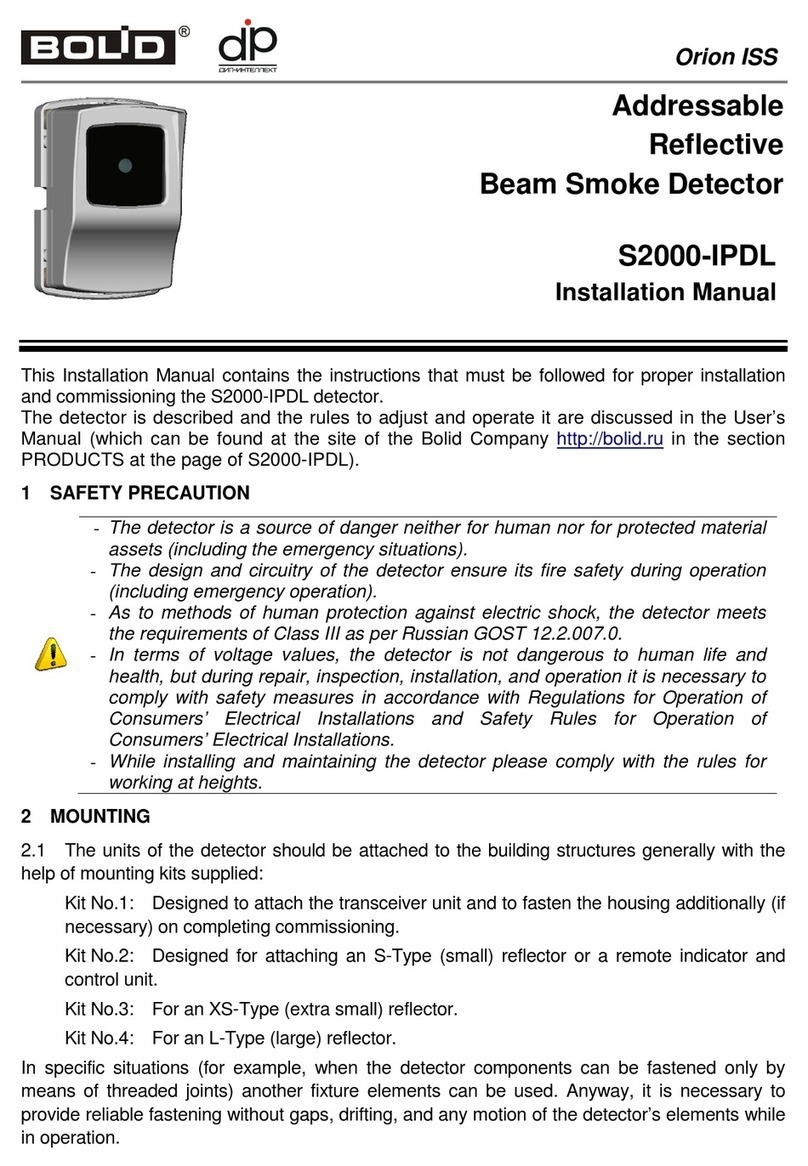
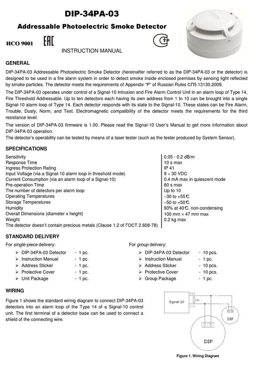
bolid S2000-IPDL User manual

ADDRESSABLE REFLECTIVE BEAM SMOKE DETECTOR
S2000-IPDL
Rev.60 (5 to 60 m)
Rev.80 (20 to 80 m)
Rev.100 (25 to 100 m)
Rev.120 (30 to 120 m)
USER’S MANUAL

3
TABLE OF CONTENTS
1
GENERAL........................................................................................................................................... 4
2
SPECIFICATIONS.............................................................................................................................. 4
3
STANDARD DELIVERY................................................................................................................... 5
4
DESIGN, MOUNTING, WIRING....................................................................................................... 6
4.1.
Safety Precautions .........................................................................................................................................................6
4.2.
Design............................................................................................................................................................................7
4.3.
Mounting the Detector...................................................................................................................................................8
4.4.
Wiring the Detector .......................................................................................................................................................9
4.5.
Mounting Location Considerations..............................................................................................................................10
5
DESCRIPTION AND OPERATION ................................................................................................ 12
5.1.
Arrangement and Operation Principle .........................................................................................................................12
6
CONFIGURING................................................................................................................................ 14
6.1.
Setting Detector Address.............................................................................................................................................14
6.2.
Selecting Operation Parameters for the Detector.........................................................................................................14
6.3.
Instructions for Aligning the Detector .........................................................................................................................15
7
TESTING OPERABILITY AND PERFORMANCE OF THE DETECTORS................................. 21
7.1.
Testing Operability......................................................................................................................................................21
7.2.
Testing Performance of the Detectors..........................................................................................................................21
8
MAINTENANCE AND REPAIR ..................................................................................................... 24
9
TROUBLESHOOTING..................................................................................................................... 25
10
TRANSPORTATION, STORAGE, DISPOSAL .............................................................................. 26
11
MANUFACTURER WARRANTY .................................................................................................. 26
12
CERTIFICATES................................................................................................................................ 26
ANNEX 1.................................................................................................................................................. 26

4
This User’s Manual provides information on studying operability principles, specifications,
configuration and operation methods of all versions of S2000-IPDL Single-Ended Addressable
Reflective Beam Smoke Detector (hereinafter referred to as the detector).
The version of the detector’s firmware is v.1.02.
1GENERAL
1.1. The detector is meant to be used in fire alarm systems in order to detect fires accompanied with
smoke in enclosed premises of various buildings and constructions and to respond with such messages
as Fire Alarm, Trouble, Test. The detector operates under a Polling Loop (PL) controller S2000-KDL
or S2000-KDL-2I in an Orion integrated security system.
1.2. The detectors are meant to be used in large premises and areas with high ceilings.
1.3. The detector relates to beam single-ended smoke projected addressable fire detectors.
1.4. The operation principle of the detectors is based on reducing of power of an optical beam when
the beam passes through a smoke-filled environment.
1.5. The detector is intended for round-the-clock operation.
2SPECIFICATIONS
Table 1 shows the key characteristics of the detector.
Table 1
Property Value
Detection Range, m:
- S2000-IPDL Rev.60
- S2000-IPDL Rev.80
- S2000-IPDL Rev.100
- S2000-IPDL Rev.120
- 5.. 60
- 20.. 80
- 25.. 100
- 30.. 120
Alarm threshold of the detector can be adaptive (dependent on the
spacing) or one of eight specified values, dB - 0.5; 0.7; 1.0; 1.3; 1.6; 1.9; 2.2; 3.0
Maximum width of the area covered by a single detector (as per the
SP5.13130 rules), meters - 9
Input Power Voltage, V - 7 to 11
Consumed Current, mA - 1.7 max
Alarm Response Time, s:
- Normal
- Maximum
- 6
- 8
Trouble Response Time, s: - 5 max
- 5 max
- 10 max
- 60 max
- 60 max
- Trouble −Memory
- Trouble −Out-of-Range
- Trouble −Beam
- Trouble −High
- Trouble −Low
Optical Beam Power Reduction Threshold for sensitivity
compensation (50%), dB - 3
Transceiver Unit Overall Dimensions, mm - 100×160×127 max
Transceiver Unit Weight, kg - 0.41 max
Remote Annunciator Overall Dimensions, mm - 55×55×21 mm
Remote Annunciator Weight, kg - 0.04 mm
Reflector Overall Dimensions, mm
- Type XS (Extra Small)
- Type S (Small)
- Type L (Large)
- 115×65×8 max
- 100×100×9 max
- 245×210×16 max

5
Property Value
Reflector Weight, kg:
- Type XS (Extra Small)
- Type S (Small)
- Type L (Large)
-
0.046 max
- 0.06 max
- 0.41 max
Operating Temperature, °С- Minus 30 to +55
Relative Humidity, % - Up to 98 at +40 °С
Resistive to sinusoidal vibration with acceleration of 0.5 g, Hz
- 10 to 155
Maximum permissible illuminance at the mounting location, lux - 12000
Ingress Protection Rating in line with GOST 14254-96 - IР40
Immune to EMI of severity levels as per:
GOST 30804.4.2 and GOST 30804.4.4
GOST 30804.4.3
- Fourth
- Third
Category relative to industrial radio interference (radio disturbance)
as per GOST 30805.22 -
Class B
Non-stop Operation - Round-the-clock
MTBF in quiescent mode, hours - At least 60000
Non-failure Operation Probability - 0.98758
Average Lifetime, years - 10
3STANDARD DELIVERY Table 2
Product
Quantity, pcs.
S2000-IPDL Rev.60
S2000-IPDL Rev.80
S2000-IPDL Rev.100
S2000-IPDL Rev.120
S2000-IPDL Transceiver Unit 1 1 1 1
XS-Type Reflector
S-Type Reflector
L-Type Reflector
Remote Indicator and Control Unit
1
1
-
1
-
-
1
1
-
-
2
1
-
-
4
1
Mounting Kit No.1:
Wood Screw 4×50 DIN 7996
Wall Plug 6×30
Tapping Screw 2.2×6.5 DIN 7981
1
4
4
2
1
4
4
2
1
4
4
2
1
4
4
2
Mounting Kit No.2:
Wood Screw 3×20 DIN 7996
Wall Plug 5×25
2
4
4
1
4
4
1
4
4
1
4
4
Mounting Kit No.3:
Wood Screw 4×30 DIN 7996
Wall Plug 6×30
1
2
2
-
-
-
-
-
-
-
-
-
Mounting Kit No.4:
Wood Screw 4×30 DIN 7996
Wall Plug 6×30
-
-
-
1
4
4
2
4
4
4
4
4
Data Sheet 1 1 1 1
Type 2 Packing
Type 3 Packing 1
- -
1 -
1 -
1

6
4DESIGN, MOUNTING, WIRING
Figure 1
4.1. Safety Precautions
–The detector is a source of danger neither for human nor for protected material assets (including
the emergency situations).
–The design and circuitry of the detector ensure its fire safety during operation (including
emergency operation).
–As to methods of human protection against electric shock, the detector meets the requirements
of Class III as per Russian GOST 12.2.007.0.
–In terms of voltage values, the detector is not dangerous to human life and health, but during
repair, inspection, installation, and operation it is necessary to comply with safety measures in
Laser
Alignment Tool
H
older
Housing
Lens
Optic Block
PCB
Base
Spring
Mounting
Base
Beamguide

7
accordance with Regulations for Operation of Consumers’ Electrical Installations and Safety
Rules for Operation of Consumers’ Electrical Installations.
–While installing and maintaining the detector please comply with the rules for working at
heights.
4.2. Design
4.2.1. The detector consists of the transceiver unit, the remote indicator and control unit, and one or
several reflectors.
4.2.2. The design of the transceiver unit is shown in Figure 1.
4.2.3. The design of the remote indicator and control unit is shown in Figure 2.
Figure 2
4.2.4. Depending on the required detection range, the detectors can come with various types and sizes
of reflectors. Figure 3 represents a reflector of the type L (Large), while Figure 4 and Figure 5
demonstrate reflectors of the type S (Small) and type XS (Extra Small) respectively.
Figure 3
Base
Cataphote

8
Figure 4 Figure 5
4.3. Mounting the Detector
4.3.1. The units of the detector should be attached to the building structures generally with the help of
mounting kits supplied:
Kit No.1: Designed to attach the transceiver unit and to fasten the housing additionally (if
necessary) on completing commissioning.
Kit No.2: Designed for attaching an S-Type (small) reflector or a remote indicator and control unit.
Kit No.3: For an XS-Type (extra small) reflector.
Kit No.4: For an L-Type (large) reflector.
In specific situations (for example, when the detector components can be fastened only by means of
threaded joints) another fixture elements can be used. Anyway, it is necessary to provide reliable
fastening without gaps, drifting, and any motion of the detector’s elements while in operation.
4.3.2. Wires can be run either in surface way or recessed. For flush wiring wires shall be lied down by
first and then the transceiver unit or remote indicator and control unit can be mounted. For surface
wiring installation order doesn’t matter.
4.3.3. Figure 6 shows the view of the transceiver unit with removed housing and open access to the
communication zone. Wires should be passed through the side holes in the base located above the side
notches in the mounting base. To provide optimal wiring location of the relevant terminal groups
should be taken into account.
4.3.4. While mounting the detectors into fire alarm systems please use wires and cables which meet
the requirements of the operation documentation for the polling loop controller.
4.3.5. The length of the cable connecting the transceiver unit with the remote indicator and control
unit should be minimized and not exceed 30 meters.
4.3.6. In the presence of regular high-power electromagnetic radiation in the premises covered by the
detectors the polling loops and other connecting wires shall be protected against electromagnetic
interference (by using twisted pair wiring, protective shielding, etc.).
WARNING: If the EMI level in the protected premises exceeds the one required by the detector
specifications represented in Table 1 then correct performance of the detectors cannot be
guaranteed.
4.3.7. The terminal blocks of the detector enable connecting wires with cross-section area 0.2 to 1.5
sq. mm (wire diameter 0.5 to 1.3 mm). If wires of 0.8 mm diameter or less are used then their ends
shall be looped.
4.3.8. The housing of the transceiver unit can be removed if only there are no locking screws in the
latches at the top and the bottom of the housing. To remove the housing, release both the latches
pressing on them and pull the housing at right angle to the lens.

9
4.3.9. To place the housing back, insert it into the latches and slightly push until it is fixed. Additional
fixation of the housing using two self-tapping screws from Mounting Kit No. 1 should be made only in
case of possible danger of mechanical effects on the detector during operation.
Figure 6
4.4. Wiring the Detector
4.4.1. The general schematic for wiring the detector is shown in Figure 7.
S2000-IPDL
XT2 XT1
11
2
33
4 4
2 +PL
- PL
+PL
- PL
1
2
3
4
XT1
- PL
+PL
S2000-KDL
Addressable
device
Addressable
device
Figure 7

10
4.4.2. The detector operates under a polling loop controller in accordance with operation conditions
defined in the PL controller configuration with the help of UProg. In UProg define the type of the
addressable device for the detector and set its Input Type to the value 3, Heat Fire. Also select the
value 2, Controlled by the S2000-KDL for the parameter Device Indication Control. Please refer to the
PL controller User’s Manual and UProg documentation to read more about selecting the type of
addressable devices and configuration parameters. Setting detector’s addresses is described in
Section 6.1 of this manual.
4.5. Mounting Location Considerations
4.5.1. While considering mounting locations for the detectors please follow the Russian regulations
SP5.13130 (Section 13).
4.5.2. The transmitter/receiver unit and the reflector (reflectors) shall be placed opposite to each other.
It is necessary to select the proper number and the proper type of reflectors. If one reflector of XS
(Extra Small) Type is used then the detector is guaranteed to align in the range of monitored distances
5 to 15 m, for one reflector of S (Small) Type the range is 15 to 60 meters, for one reflector of L
(Large) Type the range is 20 to 80 meters, for two reflectors of L Type the range is 24 to 100 meters,
and for four reflectors of L Type the range is 30 to 120 meters. As many reflectors as required with
necessary types are supplied with the detector (see Section 3). It should be taken into account that if for
a certain distance the detector can normally align with a different number of reflectors (for example,
for a distance of 40 m) then its immunity to interference will be higher when the number of reflectors
are more. This is due to the lower value of the required gain and thus to lower sensitivity to external
electromagnetic and optical interference.
4.5.3. In accordance with actual regulatory documents the maximum possible width of area protected
by a single detector is 4.5 meters on both sides of line of sight.
4.5.4. No minimum distance between lines of sight of two adjacent detectors is regulated, but it
should be borne in mind that when detectors are closely to each other they will partially reflect the
beams of each other. This doesn’t affect smoke detection but while testing the detector’s sensitivity it
is necessary to obscure a part of the reflected surface of not only its own reflector but also of adjacent
ones hitting the zone of detection pattern of the transceiver.
4.5.5. The sensitive elements of the transceiver unit should be protected against direct sunlight or
other powerful light sources (such as spotlights) which have a very powerful infrared component in
their radiation spectrum. To achieve this, the minimum required angle between the line of sight and
sunlight rays falling on the transceiver unit / reflector should be at least 10 degrees.
4.5.6. To minimize effect of lighting devices on the detector operation, it is advised to position the
transceiver as far from such devices as possible taking into account that the more the distance between
the transceiver and the reflector, the greater the influence of interfering optical radiation (due to higher
value of the gain selected during alignment).
4.5.7. The detector should be mounted to stable structures (brick walls, reinforced concrete walls,
support columns, etc.) that are not expected to experience movement, vibration, or deformation. If
unable to place the detector on rigid structures, then while mounting it to light wall panels the detector
should be attached as close to the places of fastening the panels to wall studs as possible in order to
minimize the effect of their movement on the detection pattern of the optical system. If there is a
choice, the transceiver unit should be mounted to the stable surface and the reflector should be
mounted to the less stable surface.
4.5.8. While mounting single-ended detectors which the S2000-IPDL is related to it should be taken
into account that their performance is highly dependent on stray reflections. The typical things

11
affecting the operation of single–ended detectors are ordinary ledges with very high reflectivity (as a
rule, these are zinc plated air ducts and, less commonly, lamps with shiny side surfaces) and ribbed
surfaces with the number of “ribs” which may cause stray reflections exceeding three ones per 10
meters (as a rule, these are ceiling beams or rubbed stiffeners of rafters themselves or the structures
supporting them). The value of stray reflections from a structure depends on the structure’s shape,
color, finishing surface, angle of slope relative to the beam and so on and for this reason this value
cannot be determined with a reasonable degree of accuracy, so in general the following guidelines
should be followed:
1) In such premises the distance between the central line of the beam and every obstruction
mentioned above shall be at least 0.3 m;
2) This distance can be reduced down to 0.1 m if only in the range of 1 meter to three tenths of the
distance between the transceiver unit and the reflector there are no such obstructions along the beam.
4.5.9. If it is necessary for the detector to operate through glass obstructions the last ones shall be
tilted at a slight angle (3÷10 degrees) relative to optic beam of the detector only as shown in Figure 8,
so that the beam reflected by the glass does not hit the lenses of the receiver.
Figure 8

12
5DESCRIPTION AND OPERATION
5.1. Arrangement and Operation Principle
5.1.1. The optic block of the detector is equipped with latches for attaching a laser alignment tool.
These latches provide enough accurately superposing of the optical axes of the alignment tool and the
detector unit. A spring-screw positioning mechanism is used in the detector unit to change the angle of
the slope of the radiation pattern by ±5 degrees in horizontal and vertical planes.
5.1.2. The optical system of the unit is a four-channel one. Two channels are used to form a narrow
optical beam of infrared radiation while two other channels are used for focusing received radiation.
The multichannel principle of organization of the optical system allowed: to increase the power of the
optical beam (due to two emitters), to increase the sensitivity (due to two receivers), to make the top of
the radiation pattern flatter, to reduce the influence of insects on the lens which generally result in a
positive effect on improving noise immunity and stability of the detector operation.
5.1.3. The design of the optical system provides effective suppression of the side lobes of the
radiation pattern and is reliably protected against penetration of dust, water, and insects into it. The
lens of the optical system is made of a material that is selectively transparent to IR radiation and
practically does not transmit visible light.
5.1.4. The remote indicator and control unit allows monitoring for conditions of the transceiver unit
by means of the built-in LED and provides simulating Test and Trouble signal by means of buttons and
remote connection of the IPDL-152 test station to the specific connector.
5.1.5. The principle of operation of a beam detector is based on the phenomenon of reducing of the
intensity of a beam passed through a smoke-filled environment. The S2000-IPDL relates to single-
ended detectors which are known as reflected type detectors. For such detectors the optical beam
covers the monitored distance twice, so the actual attenuation of the received signal by the smoke is
significantly higher than the value of the optical density of the monitored medium, for example, for an
optical density of 1 dB (20%) the attenuation of the signal will be 2 dB (36%).
5.1.6. To provide correct operation, the detector must be carefully adjusted during commissioning,
and a special mode is provided for this. The procedure of alignment involves superposing the radiation
pattern of the transceiver with the direction on the reflector in order to achieve the highest possible
level of the received signal for the specific conditions of use (the required range for the protected
premises).
5.1.7. On exiting the aligning mode the received signal level is written to the non-volatile memory
(EEPROM) as a given value, remains constant until the next alignment procedure, and is used to define
upper and lower limits for compensation of creeping of the current signal. If these limits are reached
then Trouble-High or Trouble-Low condition is stated.
5.1.8. A compensated value of received signal is also stored in the non-volatile memory and is
rewritten to this memory every half an hour of operation in the quiescent mode. The relevant DIP
switch provides selecting one of the two compensation rate values namely fast rate (to provide stable
operation under rapidly changing conditions) or slow rate (for early detection of slowly developing
fires).
5.1.9. Comparing the current value of a received signal with the compensated one (as with the
parameter of unpolluted air) the detector determines the value of attenuation (optical density) and
makes a decision whether or not the set thresholds of Fire Alarm and Trouble-Beam signals are
exceeded. The Trouble-Beam threshold is set by manufacturer and equal to 80% signal attenuation

13
relative to clear air. The Fire Alarm threshold is set using DIP switches and can be selected from the
set of eight specified values 10%, 15%, 20%, 25%, 30%, 35%, 40%, 50% or defined as adaptive one.
5.1.10. As the adaptive threshold is selected then the proper sensitivity will be defined by the detector
itself based on the value of the monitored distance in the premises in question. The monitored distance
value is estimated by the detector using the value of gain selected when aligning.
5.1.11. In the alignment mode the detector provides automatic selection of the optimal gain.
5.1.12. Apart from output terminals and DIP switches the communication zone incorporates test
buttons Test and Trouble, a connector for the IPDL-152 test station, and a connector for the remote
control unit.

14
6CONFIGURING
6.1. Setting Detector Address
6.1.1. The detector provides storing its polling loop address in its non-volatile memory. The factory
address of the detector is 127. An address can be given by means of the control panel, PC software
utility, or S2000-APA addressable device programmer (the rules to operate which are described in its
user’s manual). An address is assigned to the detector by sending one of the following commands:
−Set Device Address, or
−Change Device Address.
6.1.2. The command Set Device Address is used when the detector should be assigned with an address
regardless of which address is given to the detector currently. This way is suitable when, for example,
the same address is assigned with two or more devices. If so, issue a command to set the required
address from the PC or the control panel. Then, within 5 minutes max since sending the command,
press and hold pressed the TEST button of the detector / remote indicator and control unit for at least 5
second. The panel / PC shall display the events of loss of communication with the device assigned with
an old address and finding a device with the new address. If several devices were assigned with equal
addresses set then there will be no messages about loss of communications for old addresses.
6.1.3. If however it is necessary to change the detector address which is known in advance then the
Change Device Address command shall be used. Send this command specifying the old address and
the new address from the panel / PC. The panel / PC shall display events about loss of communication
with the device with the old address and establishing communications with the device with the new
address.
6.2. Selecting Operation Parameters for the Detector
6.2.1. Operation parameters for the detector are set by means of DIP switches located in the
communication zone of the PCB which is accessible on removing the transceiver unit housing.
6.2.2. The DIP switch “1” is used for switching the detector to the alignment mode – please refer to
Section 6.3 for more information.
6.2.3. The DIP switches “2” and “3” are reserved.
6.2.4. The DIP switch “4” is used for selecting the rate of compensation for slowly varying current
signal (for example, for dusted lens). If this DIP switch is set to the position ON (МЕДЛН / SLOW)
then the compensation rate will be four times slowly then when this DIP switch is switched to OFF
(БЫСТР / FAST). Fast communication rate is slightly less then maximum permissible value as per
GOST R 53325 and should be selected in cases of fast changing operation conditions, unstable
positions of structural elements of the building, or in similar cases, for example, if detectors operate in
unheated premises then it is reasonable to select always the fast compensation rate. But the slow
compensation rate shall be selected when slow fires can occur in the protected premises. Table 3
Switch Number Threshold Recommended Detection Range
5 6 7 8
OFF ON ON ON 10% (0.5 dB) 5 to 10 m
OFF ON ON OFF 15% (0.7 dB) 7 to 15 m
OFF ON OFF ON 20% (1 dB) 10 to 20 m
OFF ON OFF OFF 25% (1.3 dB) 15 to 30 m
OFF OFF ON ON 30% (1.6 dB) 25 to 40 m
OFF OFF ON OFF 35% (1.9 dB) 30 to 60 m
OFF OFF OFF ON 40% (2.2 dB) 40 to 80 m
OFF OFF OFF OFF 50% (3 dB) 50 to 120 m

15
6.2.5. The DIP switches “5”, “6”, “7”, “8” are used for setting the detector’s sensitivity. When the
DIP switch “5” is set to OFF (SPECIFIED) other three switches define one of the eight alarm
thresholds: 10%, 15%, 20%, 25%, 30%, 35%, 40%, or 50%. Table 3 shows the match between
positions of the DIP switches and defined thresholds as well as recommended detection ranges for the
selected thresholds.
6.2.6. When the DIP switch “5” is set to ON (ADAPTIVE) position then the positions of switches
“6”, “7”, and “8” specify the kind and number of reflectors to be used in the detector operation. It is the
case when the detector can correctly estimate the monitored distance based on the given gain and thus
to find out correctly the alarm threshold for this distance. Table 4 shows the match between positions
of the DIP switches and the suitable types and numbers of reflectors to use. Table 4
Switch Number Type and Number of Reflectors
5 6 7 8
ON ON ХХOne XS-Type (Extra Small) reflector
ON OFF OFF OFF One S-Type (Small) reflector
ON OFF ON OFF One L-Type (Large) reflector
ON OFF OFF ON Two L-Type (Large) reflectors
ON OFF ON ON Four L-Type (Large) reflectors
Figure 9 graphically shows average values of adaptive alarm thresholds expressed as a percentage (the
left chart) and the relevant sensitivity values in dB/m (the right chart) depending on the monitored
distance.
Figure 9
6.2.7. There are explanatory inscriptions on the detector’s PCB near the DIP switches which facilitate
setting the selected operation tactics.
6.3. Instructions for Aligning the Detector
6.3.1. General Information
6.3.1.1. Every detector must be aligned directly on site due to specificity of the beam detector
operational principle, namely the use of a narrow optical IR-beam to detect smoke. So, in order the
detector to operate correctly the maximum of the radiation pattern of its optical system should be
aligned with the direction to the reflector. The retroreflector should not be aligned if the beam angle of
incidence differs from the reflector surface normal by no more than 12 degrees, because in this case its
effectivity practically does not change.
6.3.1.2. Actually the task of alignment reduces to selecting such orientation of the transceiver for
which the received signal is the maximum possible value for the specific distance between the
10 20 30 40 50 60 70 80 90 100 110
120
m
10
20
30
40
50
60
%
10 20 30 40 50 60 70 80 90 100 110
120
m
0,02
0,04
0,06
0,08
0,1
0,12
dB/m

16
transceiver and the reflector. The transceiver can be oriented by tightening or loosening the panning
and tilting screws shown in Figure 6.
WARNING: When aligning the detector by means of LEDs or IPDL-152 tester and tightening
and loosening aligning screws neither tools no hands or other things must be in active zone of the
optical beam (between the lens and the reflector).
6.3.1.3. Three various ways (and also their combinations) can be used to align the S2000-IPDL: with
the help of LEDs, by means of an IPDL-152 tester, or using a laser pointer (laser alignment tool). In the
first case no additional service equipment is used but for two other cases prior to starting work care
should be taken to equip personnel with specified instruments.
6.3.1.4. Prior to starting specific actions to align the detector in field you are recommended to study
closely Table 5 which describes various conditions of the detector during alignment, their names which
will be used later as well as the ways of visualizing them by means of transceiver indication or on the
LCD of an IPDL-152 tester. In order to compare actual states of the detector with description for these
states in Table 5 it is advised to operate the detector in trial mode under laboratory conditions imitating
various conditions for the detector. Table 5
Condition Description Indication Text Displayed by
IPDL-152
Very Close The received signal differs from the
maximum achieved value by no more than
7% Blue «xxxx ОБЛ z»
Close The received signal differs from the
maximum achieved value by no more than
15%
Blue and white
alternately «xxxx БЛ z»
Far The received signal is much less than the
maximum achieved value White «xxxx ДАЛ z»
More The received signal is more than the
previous value Red «xxxx yyy +»
Less The received signal is less than the
previous value Amber «xxxx yyy -»
Overwriting The received signal is more than the current
maximum achieved value and this value is
overwritten
Red
Triple «Перезапись»
Too High The received signal is more than the upper
limit of the allowed self-regulation range Blue
Triple «Максимум»
Too Low The received signal is less than the lower
limit of the allowed self-regulation range White
Triple «Минимум»
Trouble-Alignment Wrong parameters of the signal in the
transient mode Amber
Triple «Н. юстиров.»
NOTES:
1) xxxx stands for a digital conventional value of the received signal converted to the absolute value
based on the actual value of conditional gain and digitized value of amplifier output signal (can be
used during aligning for maximizing);
2) yyy stands for letter identifications of states: ОБЛ (Very Close), БЛ (Close), or ДАЛ (Far);
3) z stands for the sign «+» (More) or «-» (Less);

17
4) The term “triple” for indication means that instead of standard flashes of the indicator in the
relevant color triple flashes are issued which can be visually perceived as very frequent blinking.
WARNING: As soon as the detector has entered the alignment mode the panel or PC receives a
Test or Fire Alarm message depending on the current set mode.
6.3.1.5. In general the alignment procedure is performed in such sequence:
1) Apply power to the detector;
2) Remove the housing of the transceiver unit (see Section 4.3.8);
3) Give or ensure that the required alignment parameters is given (DIP switches “4” to “8” are set
properly);
4) Activate the alignment mode by flipping the DIP switch “1” to the position ON. The network
controller shall receive a Test event;
5) Perform the coarse adjusting of the transceiver position in the horizon plane;
6) Perform the coarse adjusting of the transceiver position in the vertical plane;
7) Perform the fine adjusting of the transceiver position in the horizon plane;
8) Perform the fine adjusting of the transceiver position in the vertical plane;
9) Switch the detector to the transient mode by turning the DIP switch “1” off;
10) Wait until the detector automatically enters the operation mode, ensuring that nothing affects
the detector’s units, applied power, and active zone of the beam (for about one minute);
11) If on quitting the transient mode the detector operates in the Norm mode then it is
recommended to use the TEST and TROUBLE buttons located in the commutation zone to test issuing
the relevant messages. Otherwise, if the detector is not entering the Norm mode then it necessary to
analyze the reasons and repeat the procedure of alignment or, as a minimum, the transient mode;
12) Place the housing on the transceiver (see Section 4.3.9);
13) Verify correctness of aligning the detector by partially of full blocking the reflector and
observing the relevant messages (see Section 7.2.2).
6.3.2. Aligning Using the Built-in Indicators
6.3.2.1. When the alignment mode is switched on the detector automatically adjusts the proper gain so
that the received signal is within the allowed range. When adjusting the position of the transceiver, it is
important to correctly assess the dynamics of signal changes using Table 5.
6.3.2.2. Prior to switching the detector to the alignment mode it is recommended to assess visually
where the axis of the optical system (the perpendicular to the lens) is directed. If it is clearly misaligned
with the direction to the reflector perform an initial visual adjustment of the transceiver position. If
there are any protruding elements of the building structure (beams, struts, ducts, etc.) near the beam
path it is advised to direct the detector slightly away from these obstacles so that the signal reflected
from these obstacles does not prevent the detector from finding the true direction to the reflector.
6.3.2.3. The first stage for adjusting the position of the transceiver unit is switching the alignment
mode on followed by initial stabilization. If just after sliding the DIP switch “1” to the ON position
indication changes for flickering with red (More) and flickering triply with red (Overwriting) then you
should wait for LED pulsing with blue steadily (Very Close) and then go to the second stage of
aligning.
6.3.2.4. If initial stabilization results in stable flickering triply with blue (Two High) this means that
the received signal has exceeded the upper threshold of automatic self-regulation and measures should
be taken to reduce the signal (reduce the number or active area of reflectors, check for high-efficient
stray reflective surfaces near the transceiver, check to ensure the monitored distance is not less than the
minimum allowed value and so on).

18
6.3.2.5. If on entering the alignment mode indication changes for flickering triply with white (Two
Low) it means that the received signal is less than the lower threshold of self-regulation and measures
should be taken to increase the signal (try to define the initial direction to the reflector more accurately,
remove possible obstacles from the beam path, use more reflectors, check whether the monitored
distance is less than the maximum possible value and so on).
6.3.2.6. The second stage of adjusting the position of the transceiver unit is to search for the ideal
direction to the reflector when the received signal is as high as possible. For doing so, use a
screwdriver to slightly change the position of the transceiver unit tightening or loosening the alignment
screw in the plane selected for adjusting (for example, turning the screw in increments of quarter turn).
Continually monitor the indication performance. If during one step the LED flickers with red (More) or
triply with red (Overwriting) then keep turning, otherwise, if the LED begins flickering in amber (Less)
and after a number of steps indication enters the mode of flashing with blue and white alternately
(Close) or with white only (Far) then turn the screw the other way.
6.3.2.7. If after a number of steps when the signal increased and was rewritten it begins reducing then
it is necessary to reach flashing steadily with white (Far) to ensure that it was not a local maximum of
the signal. Only after that step back to the Very Close condition (stable blue). Now the position of the
transceiver unit can be aligned in the other plane.
6.3.2.8. If you failed to return the transceiver to the Very Close condition, for example due to position
of the transceiver being changed in the both planes simultaneously, then the value of maximum signal
determined during the entire period of alignment can be reset to zero by exiting the alignment mode
and then returning to this mode again. Of course, after that the entire adjustment procedure needs to be
repeated.
TIP: On completion of adjusting position of the transceiver unit in a particular plane we advise you to
find the midpoint of the flat top of the radiation pattern. For doing so,
−Being in the Very Close state loosen the alignment screw until the detector starts being in the
state Close;
−Tightening the screw and counting the number of turns get again through the Very Close state
until the state is Close indicating the other side of the top of the radiation pattern;
−Loosen the screw turning it half the number of steps counted during the previous operation.
Such fine adjustment will provide maximum stability for the detector in case of deformations of the
building in operation.
6.3.2.9. The third and final stage of the adjusting the position of the transceiver unit is quitting the
alignment mode with overwriting the installation parameters in the non-volatile memory of the
detector. The alignment mode can be switched off only after adjusting the position of the transceiver
unit in both planes and when the condition is Very Close (exceptionally Close). After setting the DIP
switch “1” off the detector for approximately a minute remains in the transient mode (and should be
kept motionless) quitting this mode automatically by itself after revising and overwriting all the
installation parameters to the non-volatile memory.
6.3.2.10. If the detector from the transient mode proceeds to the Norm mode then the alignment works
are completed and you can proceed to testing the detector. If, otherwise, the detector from the transient
mode enters the Trouble mode it means that the alignment parameters written to the non-volatile
memory fall out of the allowed ranges and all the alignment procedure should be repeated following
the given instruction more carefully.
6.3.3. Alignment Using an IPDL-152 Test Station
6.3.3.1. When an IPDL-152 tester is connected to the detector being in the alignment mode the LCD
of the tester displays information about current values of the gain and received signal, about the

19
average signal (which will be written in the non-volatile memory of the detector as the set and
compensated signal on quitting alignment), about conventional value of received signal converted to
the absolute value, about the current state of the detector, and the current operation mode.
6.3.3.2. The technique to align the position of the transceiver using the IPDL-152 tester is similar to
the one using the built-in LEDs (see Section 6.3.2) but it provides the following options to monitor the
level of received signal:
−Monitoring changes of the detector state according to lettering in the second line of the LCD
which completely duplicate the indication of the transceiver (see Table 5);
−Monitoring the absolute level of the received signal according to the converted value taking into
account the effective value of the gain and the digitized value of the received signal (displayed on the
LCD at the beginning of the second line);
−Monitoring the level of the received signal according to the current gain value (it shall be as
small as possible) and to the current value of the received signal (it should be as large as possible with
a minimum gain value).
6.3.4. Alignment Using a Laser Pointer
линза птическ й сист
емы
лазерный указатель
ВНИМАНИЕ!!!
Обеспечить зазор
не менее 2 мм
Figure 10
6.3.4.1. Before using a laser pointer you should carefully study its instruction manual, in particular the
safety requirements.
CAUTION: Avoid direct eye exposure to laser beam, because even at low power it can damage
your eyes.
6.3.4.2. Initially, adjusting position of the transceiver unit doesn’t require switching the alignment
mode on and even applying power to the detector.
6.3.4.3. To align the detector by means of the laser pointer do the following:
−Insert the laser pointer into the latches of the optical system as shown in Figure 10. The housing
of the laser pointer shall not touch the lens;
−Switch on the laser pointer;
−Panning and tilting the transceiver unit by means of aligning screws select such position so that it
is pointed directly at the center of the lower edge of the reflector as shown in Figure 11;
Lens
WARNING!!!
Provide a gap
of at least 2 mm
Laser pointer

20
Figure 11
−Switch the laser pointer off and take it out the latches of the optical system;
−Apply power to the detector and put it into the alignment mode by flipping the DIP switch “1”
on;
−Wait until the mode Very Close is established and stable (blue lighting) and perform the
procedure described in 6.3.2.8 (adjust the transceiver unit to the center of the flat top part of the
radiation pattern);
−Exit the alignment mode observing precautions (see Section 6.3.2.9).
light
spotting
from the laser pointer

21
7TESTING OPERABILITY AND PERFORMANCE OF THE DETECTORS
7.1. Testing Operability
7.1.1. A full-range verification of the detector’s operability before installation should be done only in
case of mandatory requirements of on-receipt inspection for the products (for example, for use on
special objects) or if you have doubts about its performance (for example, before sending or after
receiving the detector after repair).
7.1.2. If it is impossible or too difficult to pose the transceiver unit and the reflector as far from each
other as required then it is recommended to use the surface of a wall or a ceiling as a reflector, for
example to put the transceiver on a table with the lens facing up using the ceiling as a reflector.
7.1.3. For testing operability, power up the control panel or PC and the polling loop controller with
the detector connected to the last one.
7.1.4. Activate the alignment mode by sliding the DIP switch “1” to the ON position. Visually inspect
fast pulsing (faster than five flashes per second) in red (which means selecting an optimal gain with
overwriting the maximum achieved level of received signal) followed by pulsing most of the time in
blue (Very Close) with normal frequency (approximately twice per second). In particular, there can be
rare flashes with amber (Less) or red (More). Having achieved such condition, you can terminate the
alignment by sliding the DIP switch “1” to the OFF position and waiting for approximately one minute
until the detector automatically quits this mode having rewritten new values of installation parameters
into the non-volatile memory.
WARNING: After detector’s having entered to the alignment mode the control panel or PC shall
receive a Test of Fire Alarm event depending on the current settings.
7.1.5. If the alignment mode has established but the LED rapidly flashes with white (Too Low) or blue
(Two High) then take measures to increase the reflected signal in the first case or to reduce the
reflected signal in the second one. If you failed to alter this performance then with great probability the
detector is improper.
7.1.6. If the detector exits the alignment mode normally it shall enter in the Norm state indicating this
by red flashing once per four seconds.
7.1.7. Arm the detector.
7.1.8. Press the TROUBLE button on the detector’s board and observe flashing with amber (“Trouble
in Progress”) followed by flashing in red with the trouble pattern. After releasing the button the
detector will enter normal state in some time.
7.1.9. Press the TEST button on the detector’s board and observe fast green pulsing at first (“Test in
Progress”) followed by solid illuminating with red. The full-range verification of the operability of the
detector is completed now. If any problems were detected during verification the detector should be
sent to the manufacturer for repair, however, it is recommended to contact preliminary the technical
support service in order to verify the validity of the checks performed.
7.2. Testing Performance of the Detectors
7.2.1. General Guidelines for Testing
7.2.1.1. Performance of visual indication of detector’s displaying its conditions in the operation mode
and in the alignment mode is crucially different. Table 6 contains descriptions of various conditions of
the detector for the operation mode, their textual names, and the ways to display these conditions by
means of detector’s indication and on the LCD of an IPDL-152 test station. Prior to testing the detector
please read and understand the information from Table 6.
Other manuals for S2000-IPDL
1
Table of contents
Other bolid Smoke Alarm manuals