Boltek ERL-10 Specifications
BOLTEK CORPORATION
LightningDetection
ERL-10 Programmable
Output Relay Module
Installation/Operators Guide

SEE DISCLAIMER ON REVERSE
B O L T E K L I G H T N I N G D E T E C T I O N
ERL-10 Output Relay Module
Disclaimer
ERL-10 lightning data is only approximate and should not be used for safety applications. Strike and storm
locations indicated and alarm statuses may be erroneous and should not be used to safeguard personnel,
equipment or data.
Neither Boltek Corporation nor its affiliates shall be liable to the purchaser of this product or third parties
for damages, losses, costs, or expenses incurred by purchaser or third parties as a result of use, misuse,
accident, or abuse.
Notwithstanding the above Boltek Corp’s liability shall not exceed the purchase price of the equipment.
THIS EQUIPMENT IS NOT TO BE USED FOR SAFETY PURPOSES
©2020 Boltek Corporation
Boltek Corporation
4 Stonebridge Dr. Unit 2
Port Colborne, ON L3K5V5
Canada
Email: info@boltek.com
Web: www.boltek.com
Phone (905) 734-8045 • Fax (905) 734-9049

FCC Compliance Statement
For United States Users
This equipment is tested and found to comply with the limits for a Class B digital device, pursuant to Part 15 of
the FCC Rules. These limits are designed to provide reasonable protection against harmful interference in a
residential installation. This equipment generates, uses, and can radiate radio frequency energy and, if not installed
and used in accordance with the instructions, may cause harmful interference to radio or television reception.
However, there is no guarantee that interference will not occur in a particular installation. If this equipment does
cause interference to radio and television reception, which can be determined by turning the equipment on and off,
the user is encouraged to try to correct the interference by one or more of the following measures.
•Reorient or relocate the receiving antenna.
•Increase the separation between the equipment and the receiver.
•Connect the equipment into an outlet on a circuit different from that to which the receiver is connected.
•Consult the dealer or an experienced radio/TV technician for help.
WARNING
The connection of a non-shielded equipment interface cable to this equipment will invalidate the FCC Certification
of this device and may cause interference levels which exceed the limits established by the FCC for this equipment.
It is the responsibility of the user to use a shielded interface cable with this device. If this equipment has more than
one interface connector, do not leave cables connected to unused interfaces. Changes or modifications not
expressly approved by the manufacturer could void the user’s authority to operate the equipment.
For Canadian Users
This Class B digital apparatus meets all requirements of the Canadian Interference-Causing Equipment
Regulations.
Cet appareil numérique de la class B respecte toutes les exigences du Règlement sur le materiel brouilleur du
Canada.
WARNING: LIGHTNING AND ELECTRIC FIELD DATA IS ONLY APPROXIMATE
AND SHOULD NOT BE USED FOR SAFETY APPLICATIONS. ELECTRIC FIELD
READINGS, STRIKE DISTANCES AND ALARM STATUSES MAY BE ERRONEOUS
AND SHOULD NOT BE USED AS A PRIMARY MEANS TO SAFEGUARD PERSONS,
EQUIPMENT OR DATA.

Table of Contents
Introduction........................................................................................................... 1
Quick Start Instructions ....................................................................................... 2
Software................................................................................................................. 3
ERL-10 display software installation................................................................... 3
ERL-10 USB driver installation........................................................................... 4
ERL-10 Alarm Configuration............................................................................... 5
Alarm Config tab settings..................................................................................... 6
Coincidence Config Tab....................................................................................... 8
Relays Config Tab................................................................................................ 8
USB Message Config Tab .................................................................................... 8
Configuration Buttons.......................................................................................... 8
ERL-10 Status Monitor....................................................................................... 10
ERL-10 Event Viewer......................................................................................... 12
Operation............................................................................................................. 14
Operation Modes................................................................................................ 14
Input Connection Modes .................................................................................... 15
Connectors ......................................................................................................... 20
Overview.............................................................................................................. 22
Front Panel LEDs .............................................................................................. 22
USB Messages and Commands.......................................................................... 25
USB/RS485 Messages
............................................................................ 25
ERL-10 Connections........................................................................................... 28
Specifications....................................................................................................... 31
ERL-10 Hardware Specifications ...................................................................... 31
Software Specifications ...................................................................................... 31

Table of Figures
Figure 1: ERL-10 Status Monitor Display –All Clear state ..................................................................................... 3
Figure 2: ERL10 Config Utility Window ....................................................................................................................... 5
Figure 3: ERL-10 Status Monitor Display - Active Alarms State.........................................................................10
Figure 4: Warning History Log ......................................................................................................................................11
Figure 5: Historical Event Viewer .................................................................................................................................12
Figure 6: Alarm Time Graph...........................................................................................................................................13
Figure 7: Alarm Time Graph Zoomed In....................................................................................................................13
Figure 8: RS485 Input Jumper Settings .......................................................................................................................15
Figure 9: ERL-10 Kit-2 with RS-485 Input. ................................................................................................................16
Figure 10: Fiber Optic Input Jumper Settings...........................................................................................................17
Figure 11: ERL-10 Kit-2 with Fiber Optic Input.......................................................................................................18
Figure 12: ERL-10 Kit-1 with Fiber Optic Input/RS485 Output.........................................................................19
Figure 13: Relay Outputs ..................................................................................................................................................20
Figure 14: Relay connection example. .........................................................................................................................21
Figure 15: ERL-10 Top View ...........................................................................................................................................22
Figure 16: ERL-10 Kit-1 alternate connection............................................................................................................28
Figure 17: ERL-10 Kit-2 Fiber Optic Input with Serial Server. ..........................................................................29
Figure 18: ERL-10 Kit-2 with Status Monitor and NexStorm Display. .............................................................30
C H A P T E R 1 - I N T R O D U C T I O N
1
Introduction
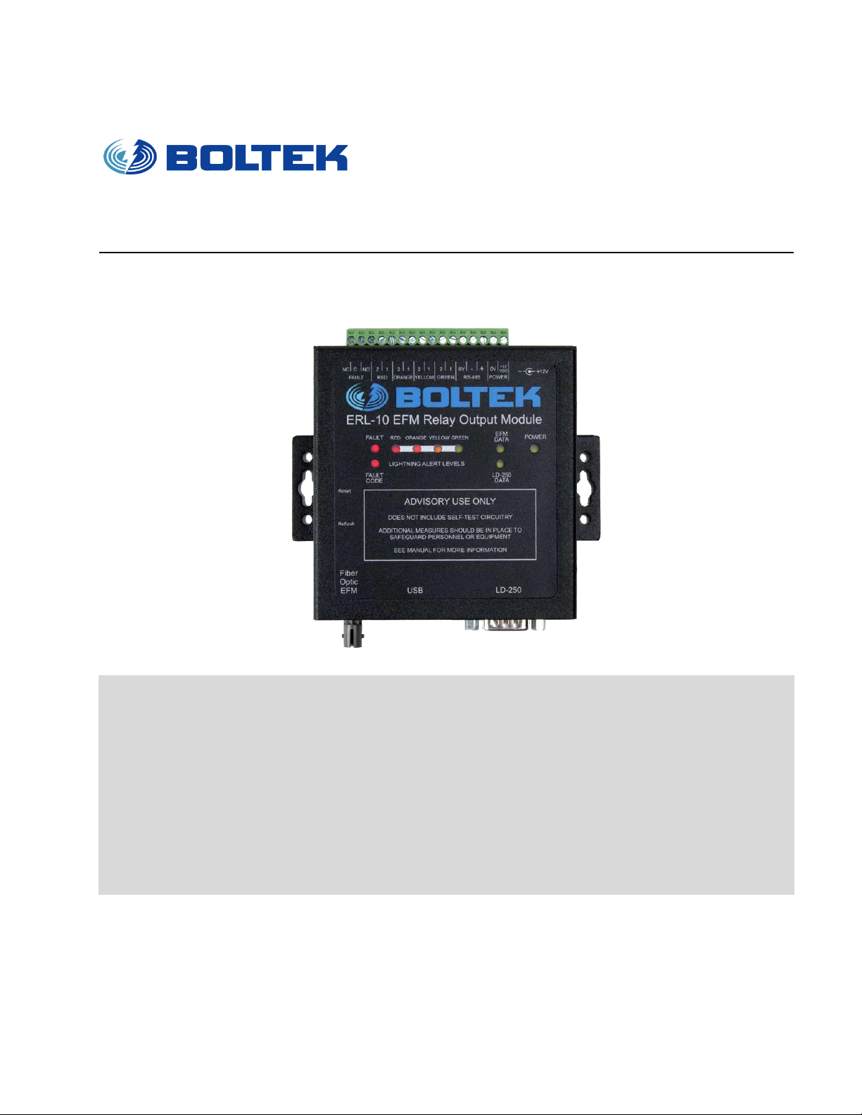
he ERL-10 Programmable Output Relay Module puts a live lightning status alarm
on your laptop or desktop computer, along with relay connections to activate
lighting or audible devices. The ERL-10 is suitable for use with a computer or as a
stand-alone relay module for fixed installations.
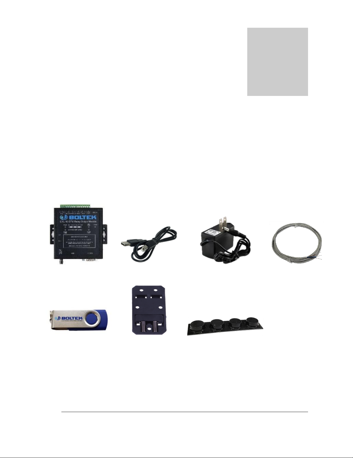
Your ERL-10 package should contain:
1: ERL-10 Relay
2: USB Cable
3: 12V DC Power Adapter
4: RS485 wire
5: USB flash drive
6: DIN rail mount
7: Rubber feet
Please check that all ERL-10 parts are included.
Chapter
1
T

C H A P T E R 1 - I N T R O D U C T I O N
2
Quick Start Instructions
1) Install EFM-100 (and LD-250 if purchased). Please refer to user manuals of each
detector for installation details.
2) Connect EFM-100 fiber cable to ERL-10 fiber connector or the RS485 wire from
the EFA-21 terminal to the ERL-10 terminal
3) Connect (optional) DB9 cable from LD-250 to ERL-10 RS232 connector
4) Connect the USB cable from your computer USB port to the USB connector of
your ERL-10.
5) Plug in the AC power adapter into the lead of the ERL-10 and into an AC outlet.
The ERL-10 will power up. All of the LEDs will illuminate the indicator lights for
2 seconds then the EFM Data LED will start blinking. If the fault LED stays on,
check EFM-100 power and connection or refer to Fault Code chart listed in
Appendix A
6) After the ERL-10 is powered up, the USB drivers should automatically install if
there is an active internet connection on the computer. If there is no internet
connection, the USB driver install program can be found on the Boltek USB Flash
Drive in the folder:\USB_DRIVER\.
7) Run the ERL-10 program executable on the USB Flash Drive to install the
Configuration, Monitor, and Data Viewer applications.
8) After installation has completed, run the Config application to set alarm parameters
and click “Write config to ERL-10” to save settings to the ERL-10
9) If viewing alarm status on a PC or Laptop, run the Status Monitor software to view
active alarms/all clear status.
Unless changed, once the ERL-10 is powered up, it goes into Survey Mode for a default
time of 20 minutes. If no lightning activity is detected, then the All Clear status light will
illuminate and normal operation of the device will begin.
C H A P T E R 2 - SOF T W A R E
3
Software
ERL-10 display software installation
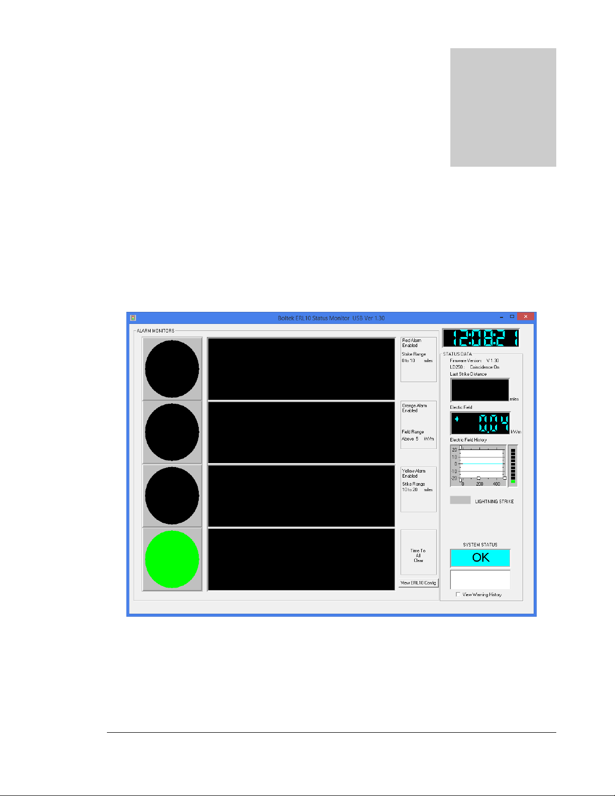
Figure 1: ERL-10 Status Monitor Display –All Clear state
Chapter
2

C H A P T E R 2 - SOF T W A R E
4
Insert the provided Boltek USB Flash Drive into an available USB port. If the setup program does
not run automatically, you can start it from the Windows Run command window and browse the
USB drive for the ERL10_V130_Install.exe file (may vary if version number is different) and click
open to start installation.
The software installation package installs three programs that work specifically with the ERL-10:
❖ERL10 Config –Configures all of the alarm parameters along with enabling/disabling
Coincidence mode, and relay switch states.
❖ERL10 Status Monitor –Displays field reading, last strike distance, alarm status and
configuration. A USB and RS485 connection version are both installed for convenience.
❖Event Viewer –Opens archived daily data files created automatically from the Status
Monitor software to view and analyze historical alarm and lightning activity.
ERL-10 USB driver installation
1) Plug the square end of the USB cable into the EFA-20, and the other end of the cable
into an available USB port on a Laptop or PC.
2) Windows should automatically install the driver if there is an internet connection.
If the “Found New Hardware Wizard” appeared in step 1 or there is no active internet
connection:
a) Click Cancel if Found New Hardware Wizard window pops up.
b) Insert EFM-100 Software USB Flash Drive and Open Computer (or My Computer)
and go into USB Flash Drive. Open
USB_DRIVER
folder and run
ERL10_USB_Driver_Install.exe
c) Click Yes (or Continue) if Allow Changes to computer message pops up.
d) When Driver Setup window appears, click Next
e) Browse for a different installation folder or leave default folder then click Install
f) Setup will extract some files then click Next when USB Driver Installer window
appears.
g) Read End User Agreement then select "I accept this EULA" and click Next
h) After the two drivers (BOLTEK CDM Driver Package & FTDI CDM Driver Package)
have been successfully installed, click Finish
Click Close on Driver setup window, and installation is complete.
C H A P T E R 2 - S O F T W A R E
5
ERL-10 Alarm Configuration
After the hardware, drivers and software are setup and installed, the ERL-10 alarm parameters can
be configured with the ERL10 Config software. The ERL-10 needs to be connected to the
PC/Laptop with the USB cable in order to modify the alarm configuration.
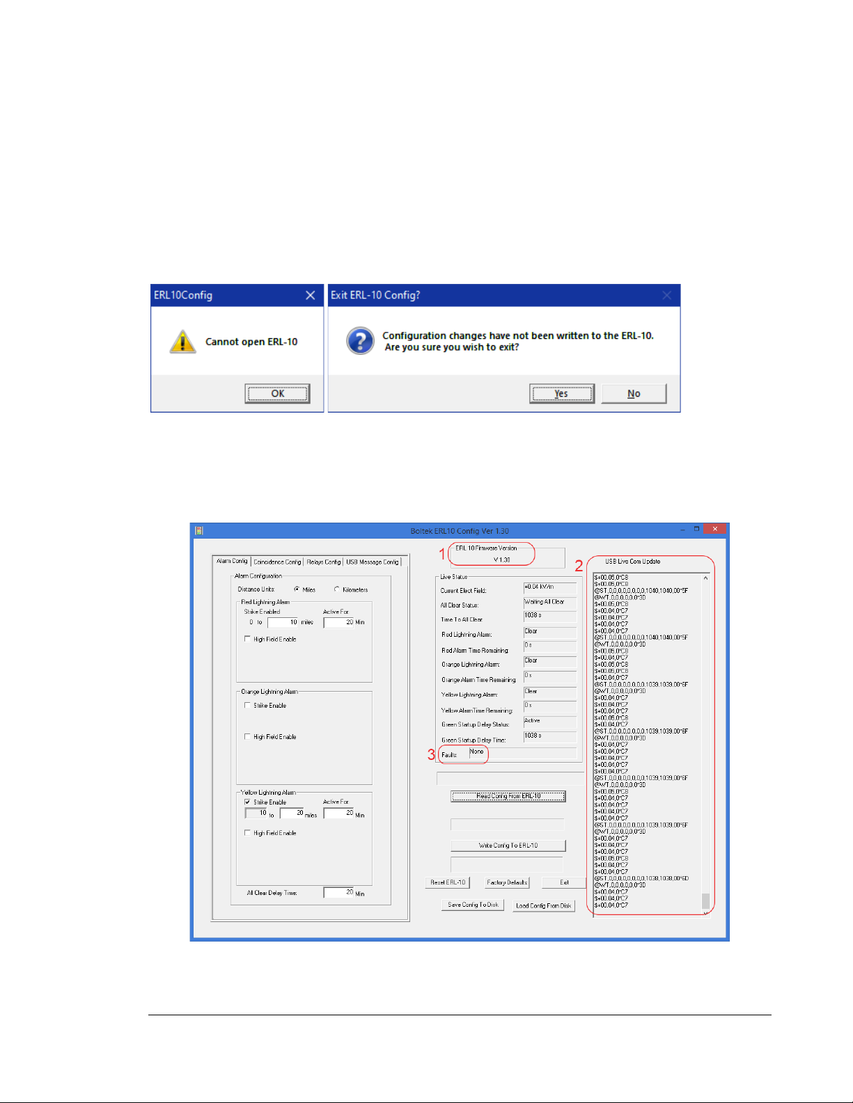
If you see these message windows pop up when starting the Configuration Utility, click the OK
button then click the Yes button.
Check the top of the ERL-10 relay module and verify that the power LED is on and the USB cable
is properly connected.
To verify connectivity, confirm the correct firmware version (1), data scrolling in the USB Live Com
Update Window (2) and if there are any faults (3). See figure below for example.
Figure 2: ERL10 Config Utility Window

C H A P T E R 2 - S O F T W A R E
6
Alarm Config tab settings
Distance Units
•Select Miles or Kilometers by clicking on the corresponding radio button
Red Lightning Alarm
•The Red strike alarm is always active and cannot be disabled.
•The
Strike Enable
distance box cannot be set to the same or exceed an Orange or Yellow
enabled strike alarm distance. The set distance cannot exceed 20 miles/32km using just the
EFM-100 sensor or 40 miles/64km with coincidence mode enabled.
•The
Active For
box sets the duration that the Red alarm will remain active when a strike is
detected within the set distance range. This value can be set between 1 and 60 minutes.
•The
High Field Enable
box enables/disables a Red High Field alarm.
•The
Above
box is used to set the desired magnitude of the electrical field to activate
the alarm and represents the same positive and negative field levels. This value
cannot be the same or less than an active orange or yellow high field alarm.
•The
Delay On
time is the length of time the set electric field magnitude must
remain above before the alarm is activated. If the electric field magnitude drops
below the set point before the delay expires, the delay timer will be reset. This value
can be set between 1 and 600 seconds.
•The
Active For
box sets the duration that the Red alarm will remain active when
this high field alarm is activated. This value can be set between 1 and 60 minutes.
Orange Lightning Alarm
•The Orange strike alarm can be enabled or disabled.
•The
Strike Enable
distance box cannot be set to the same or lower distance than the Red
strike alarm. The set distance cannot exceed 20 miles/32km using just the EFM-100 sensor
or 40 miles/64km with coincidence mode enabled.
•The
Active For
box sets the duration that the Orange alarm will remain active when a
strike is detected within the set distance range. This value can be set between 1 and 60
minutes.
•The
High Field Enable
box enables/disables an Orange High Field alarm.
•The
Above
box is used to set the desired magnitude of the electrical field to activate
the alarm and represents the same positive and negative field levels. This value
cannot be the same or lower than the active Yellow high field alarm level. It also
cannot be set to the same level or higher than the Red high field alarm if enabled.
•The
Delay On
time is the length of time the set electric field magnitude must
remain above before the alarm is activated. If the electric field magnitude drops
below the set point before the delay expires, the delay timer will be reset. This value
can be set between 1 and 600 seconds.
•The
Active For
box sets the duration that the Red alarm will remain active when
this high field alarm is activated. This value can be set between 1 and 60 minutes.

C H A P T E R 2 - S O F T W A R E
7
Yellow Lightning Alarm
•The Yellow strike alarm can be enabled or disabled.
•The
Strike Enable
distance box cannot be set to the same or lower distance than the Red
(or Orange if enabled) strike alarm. The set distance cannot exceed 40 miles or 64km.
•The
Active For
box sets the duration that the Yellow alarm will remain active when a strike
is detected within the set distance range. The set distance cannot exceed 20 miles/32km
using just the EFM-100 sensor or 40 miles/64km with coincidence mode enabled.
•The
High Field Enable
box enables/disables a Yellow High Field alarm.
•The
Above
box is used to set the desired magnitude of the electrical field to activate
the alarm and represents the same positive and negative field levels. This value
cannot be higher than an active Red or Orange high field alarm level.
•The
Delay On
time is the length of time the set electric field magnitude must
remain above before the alarm is activated. If the electric field magnitude drops
below the set point before the delay expires, the delay timer will be reset. This value
can be set between 1 and 600 seconds.
•The
Active For
box sets the duration that the Yellow alarm will remain active when
this high field alarm is activated. This value can be set between 1 and 60 minutes.
All Clear Delay Time
•This timer represents the length of time to wait for no alarm activity until the Green All
Clear status is enabled. If a strike or high field alarm triggers before this expires, the timer
will reset. This value can be set between 1 and 60 minutes.

C H A P T E R 2 - S O F T W A R E
8
Coincidence Config Tab
This tab allows the user to enable or disable the coincidence mode feature of the ERL-10 when
using both EFM-100 and LD-250 sensors.
Select
LD250 Enable
if the LD-250 lightning detector is connected to the ERL-10’s RS232
connector. De-select (default) if no LD-250 is connected to the ERL-10. The Fault LED will
illuminate if this option is enabled and the LD-250 lightning detector unit is powered off or not
connected.
Relays Config Tab
This tab allows the user to program the normal state of the output relay switches for the Red Alarm
Relay, Orange Alarm Relay, Yellow Alarm Relay, and Green All Clear Relay. The default setting is
Normally Open for all relays. The switch states can be configured based on how the user hardware
connected to the terminal block operates.
USB Message Config Tab
This tab displays what messages are transmitted from the ERL-10, these settings can’t be modified
Configuration Buttons
The configuration buttons allow the user to send and read configurations to and from the ERL-10
Read Config From ERL-10
Displays last saved configuration parameters of the ERL-10. A message will appear above this
button if any configuration changes have been made.
Write Config To ERL-10
Uploads and saves the parameters that are displayed in the configuration software to the ERL-10.
Reset ERL-10
Clicking this button will clear any active alarms and reset the power on the ERL-10.
Factory Defaults
This button will reconfigure the ERL-10 to its default parameters. If there are any active alarms, they
will remain on after clicking this button.

C H A P T E R 2 - S O F T W A R E
9
Save Config To Disk
This button saves the current configuration parameters to a data file on the PC or Laptop. This is
useful when running multiple sites. Once saved, the file can then be emailed or saved on a flash drive
or disk to be loaded on another ERL-10. You can also save multiple files when testing for different
parameters.
Load Config From Disk
This is used for loading previously saved configuration files. There are eight pre-configured files that
come with the ERL-10 software package for convenience:
2AlarmStrikeAndFieldWithCoincidence.cfg
2AlarmStrikeAndFieldWithNoCoincidence.cfg
2AlarmStrikeWithCoincidence.cfg
2AlarmStrikeWithNoCoincidence.cfg
3AlarmStrikeAndFieldWithCoincidence.cfg
3AlarmStrikeAndFieldWithNoCoincidence.cfg
3AlarmStrikeWithCoincidence.cfg
3AlarmStrikeWithNoCoincidence.cfg
Exit
Closes the ERL-10 Config program.

C H A P T E R 2 - S O F T W A R E
10
ERL-10 Status Monitor
Figure 3: ERL-10 Status Monitor Display - Active Alarms State
Alarm Monitors
Displays the alarms that are enabled on the ERL-10 as well as any active countdown timers and their
respective parameters.
View ERL10 Config
Displays all of the current configuration status of the ERL-10. This display is read only and
parameters cannot be changed in this window.
Status Data
Displays ERL-10 firmware version of the ERL-10, coincidence mode on or off along with the last
strike distance detected and current electric field levels. There are slider bars on the Electric Field
History window that can be used to zoom in and out of the graph. The Lightning Strike box will
flash the corresponding alarm color when a strike is detected within each set distance parameters.
System Status box will display OK if everything is running properly, or it will display Fault if there is
a communications error or other fault with the ERL-10.
C H A P T E R 2 - S O F T W A R E
11
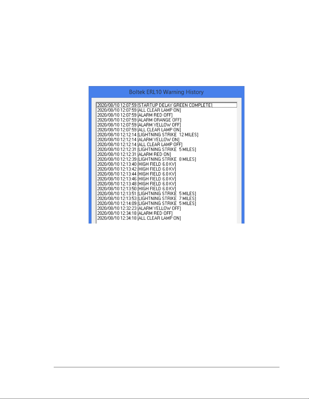
View Warning History
Displays a timestamped historical display of the current day’s relay activity. Activity is only recorded
while the Status Monitor software is running.
Figure 4: Warning History Log

C H A P T E R 2 - S O F T W A R E
12
ERL-10 Event Viewer
Figure 5: Historical Event Viewer
The event viewer is used to display historical alarm and lightning strike activity. A daily data file is
automatically created and updated by the ERL10 Status Monitor program while it is running. The
ERL-10 Output Relay Module does not store data and historical activity cannot be retrieved if the
software is not running.

C H A P T E R 3 - O P E R A T I O N
13
Open Event File
Click this button to open an historical data file. Select the preferred file to view activity for that day.
A window with a graph will pop up
Figure 6: Alarm Time Graph
Zoom handles are located at the bottom of the graph to expand a time frame of interest for an easier
view when looking at the relay state changes.
Figure 7: Alarm Time Graph Zoomed In

C H A P T E R 3 - O P E R A T I O N
14
Operation
Operation Modes
The ERL-10 can be configured to activate up to three alarm levels, with either a single sensor
(EFM-100) or two sensors (EFM-100 & LD-250). It can also be used as a stand-alone device,
with external devices connected to the relay contacts, or connected to a PC/Laptop. Alarm
status is always shown with the LED’s on the top of the ERL-10 and can also been seen with
the ERL-10 status monitor software when connected to a PC/Laptop through USB or RS485
connection.
Coincidence Mode
This mode will receive data from both the EFM-100 and LD-250 to virtually eliminate any false
strikes that may occur with precipitation noise or objects that could interfere with the normal
operation of the EFM-100. Coincidence mode is only applicable within the EFM-100 detection
range (0-20 miles/0-32km). Lightning strike detection can be extended further than the EFM-
100 range in this mode, in which case would only be detected by the LD-250 and could be
subject to false strikes. High electrical field alarms can also be set which are measured by the
incoming EFM-100 data.
Single Sensor Mode (Non Coincidence)
This mode will receive data from only the EFM-100 and will activate high field alarms or
lightning strike alarms set up to 24 miles (38km) away. Single sensor mode is also liable to
display false strikes from heavy precipitation or other objects that could interfere with the
normal operation of the detector.
Chapter
3

C H A P T E R 3 - O P E R A T I O N
15
Input Connection Modes
RS485 Input Mode
The factory default input mode of the ERL-10 is setup to receive data from the
RS485 input on the terminal block from the EFA-21 power/data module. The diagram below
indicates the jumper settings for this input method. If switching from the fiber optic input,
access the circuit board by removing the four case screws and cover. The jumpers shown below
indicate the correct position.
Figure 8: RS485 Input Jumper Settings
Note: the RS485 communication on the ERL-10 is one-way and can only receive data (default)
or transmit data depending on the jumper settings.
See connection diagram on next page for the default setup using this input method.
Table of contents


