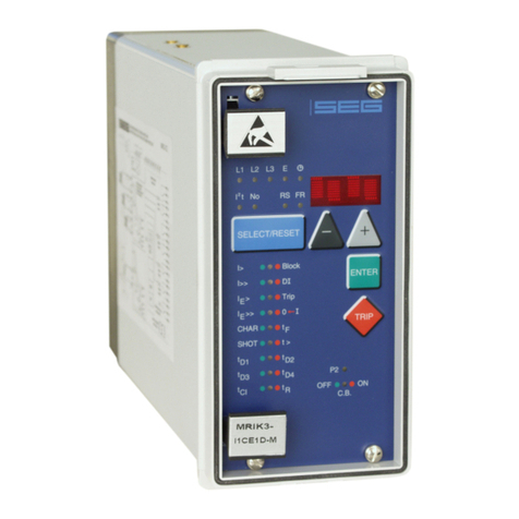
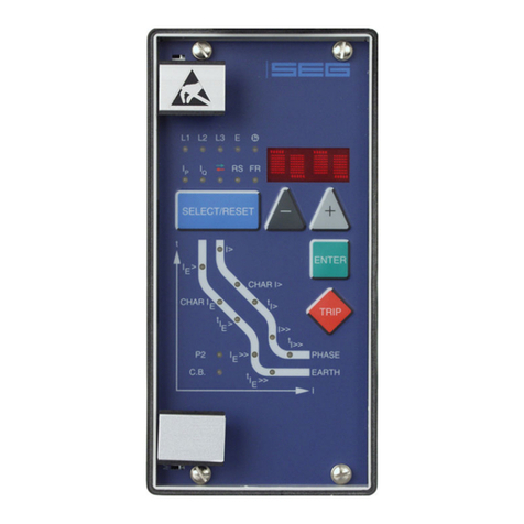
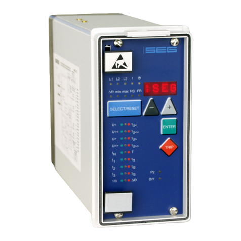
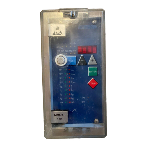
Seg MRM3 User manual

MRM3
PROTECTION TECHNOLOGY
MADE SIMPLE
MOTOR PROTECTION RELAY
HighTECH Line
MOTOR PROTECTION RELAY
Revision: B
Original document
English
MANUAL

SEG Electronics GmbH Manual MRM3-2
2 DOK-TD-MRM3-2, Rev. B
SEG Electronics reserves the right to update any portion of this publication at any time.
Information provided by SEG Electronics is believed to be correct and reliable.
However, no responsibility is assumed by SEG Electronics unless otherwise expressly undertaken.
© SEG Electronics 1994–2020. All rights reserved.

Manual MRM3-2 SEG Electronics GmbH
DOK-TD-MRM3-2, Rev. B 3
Contents
1. Introduction and Application ......................................................................6
2. Characteristics and Features......................................................................7
3. Design...........................................................................................................8
3.1 Connections ........................................................................................................................8
3.1.1 Analog Inputs ..................................................................................................................9
3.1.2 Output Relays..................................................................................................................9
3.1.3 Digital Inputs..................................................................................................................10
3.1.4 Low/High Range of the Digital Inputs............................................................................10
3.2 Front plate.........................................................................................................................11
3.2.1 Indicating LEDs.............................................................................................................12
3.2.2 Adjusting LEDs..............................................................................................................12
3.3 Analog part........................................................................................................................12
3.4 Digital part.........................................................................................................................13
4. Working Principle ......................................................................................14
4.1 Start Recognition...............................................................................................................14
4.1.1 Criteria for Blocking the Start ........................................................................................16
4.2 Starting time......................................................................................................................18
4.3 Thermal Image..................................................................................................................18
4.4 Requirement on the Main Current Transformers..............................................................19
5. Operation and Adjustments......................................................................20
5.1 Displayed text for parameter settings ...............................................................................20
5.2 Setting Procedure .............................................................................................................21
5.3 System parameters...........................................................................................................21
5.3.1 Presentation of Measuring Values as Primary Quantities on the Display (Iprim Phase) 21
5.3.2 Rated -Frequency..........................................................................................................21
5.3.3 Operating Hour Meter (h)..............................................................................................21
5.3.4 Number of Motor Starts (No.)........................................................................................21
5.3.5 Indication of pickup........................................................................................................21
5.3.6 Parameter Set Changeover Switch (P2).......................................................................22
5.4 Protection Parameters ......................................................................................................22
5.4.1 Thermal Overload Protection (k x IB)............................................................................22
5.4.2 Warning/Tripping with thermal Overload.......................................................................22
5.4.3 Tripping Delay for Thermal Overload............................................................................22
5.4.4 Heating Period Constant Wand Cooling-Down Time Factor C...................................22
5.4.5 t2x and t6x Minimal Trip Time During the Starting Process..........................................23
5.4.6 Phase Undercurrent Element (I<) .................................................................................23
5.4.7 Phase Over current Element (I>) ..................................................................................23
5.4.8 Trip Characteristics for the Phase Over current Element (I>+CHAR) ..........................23
5.4.9 Tripping Time or Time Factor for the Phase Over current Element (I>+t>)..................24
5.4.10 Reset Mode for the Trip Characteristics in the Phase Current Path (I>+CHAR+t>).24
5.4.11 Phase Short-Circuit Trip (I>>) and (I>>+Start)..........................................................24
5.4.12 Negative Phase Sequence........................................................................................25
5.4.13 Earth Fault Element (IE>)..........................................................................................25
5.4.14 Switching Over Warning/Tripping..............................................................................25
5.4.15 Trip Characteristics for the Earth-Fault Element (IE>+CHAR) .................................25
5.4.16 Tripping Time or Time Factor for the Earth Fault Element (IE>+t>) .........................26
5.4.17 Reset Time for the Earth Fault Element (IE>+CHAR+t>).........................................26
5.4.18 Tripping Time for the CB Failure-Protection (CB+t>)................................................26
5.4.19 External Trip (delayed)(Trip+t>)................................................................................26
5.4.20 Trip Blocking in case of Excessive Phase Current (Trip+Block)...............................26
5.5 Start Supervision...............................................................................................................27
5.5.1 Duration of a Start Cycle (No.+Start) ............................................................................27
5.5.2 Number of Starts per Cycle (No.+Start)........................................................................27
5.5.3 Start Blocking Time (Start+Block+t>)............................................................................27
5.5.4 Characteristic for the Starting Time...............................................................................27
5.5.5 Rated starting current I_Start........................................................................................27
5.5.6 Maximal Start Time (Start+t>).......................................................................................28

SEG Electronics GmbH Manual MRM3-2
4 DOK-TD-MRM3-2, Rev. B
5.5.7 Start-up recognition time or Motor Running time..........................................................28
5.5.8 Stopping time................................................................................................................28
5.6 Interface Parameters........................................................................................................28
5.6.1 Adjustment of the Slave-Address (RS).........................................................................28
5.6.2 Adjustment of the Baud-Rate (only for Modbus Protocol)............................................28
5.6.3 Adjustment of the Parity (only for Modbus-Protocol)....................................................28
5.7 Recorder (FR)...................................................................................................................29
5.7.1 Fault Recorder or Disturbance Recorder......................................................................29
5.7.2 Number of Fault Recordings.........................................................................................30
5.7.3 Adjustment of the Trigger Event...................................................................................30
5.7.4 Pre-Trigger Time (Tvor)..................................................................................................30
5.8 Setting of the Clock...........................................................................................................31
5.9 Additional Functions .........................................................................................................32
5.9.1Blocking of the Protective Functions.............................................................................32
5.9.2 Allocation of the Reset Functions.................................................................................33
5.9.3 Allocation of the Output Relays ....................................................................................34
5.10 Measuring Value and Fault Indications ............................................................................36
5.10.1 Measuring Value Indications.....................................................................................36
5.10.2 Units of the Displayed Measuring Values.................................................................36
5.10.3 Indication of the Fault Data.......................................................................................36
5.10.4 Fault Memory............................................................................................................37
5.11 Reset.................................................................................................................................38
5.11.1 Erasure of the Fault Memory....................................................................................38
5.11.2 Reset of the Thermal Memory..................................................................................38
5.12 Digital Inputs.....................................................................................................................39
5.12.1 Parameter Set Changeover Switch ..........................................................................39
5.12.2 External Trigger of the Fault Recorder .....................................................................39
5.12.3 Recognition of “Motor Running” Condition ...............................................................39
5.12.4 Undelayed External Trip...........................................................................................39
5.12.5 Delayed External Trip ...............................................................................................39
6. Notes on Relay Tests and Commissioning .............................................40
6.1 Connection of the auxiliary voltage...................................................................................40
6.2 Testing of Output Relays and LEDs .................................................................................40
6.3 Test circuit for MRM3-2 ....................................................................................................41
6.3.1 Checking of Input Circuits and of the Measuring Values..............................................41
6.3.2 Testing the START-STOP-RUNNING Recognition......................................................41
6.3.3 Testing the Pick-Up and Disengaging Values ..............................................................42
6.3.4 Testing the maximum starting time...............................................................................42
6.3.5 Testing the thermal image ............................................................................................42
6.3.6 Testing the Control Inputs.............................................................................................42
6.3.7 Testing the CB Failure Protection.................................................................................42
6.4 Primary Test......................................................................................................................43
6.5 Maintenance .....................................................................................................................43
7. Technical Data............................................................................................44
7.1 Measuring input ................................................................................................................44
7.2 Common data ...................................................................................................................44
7.3 Setting ranges and steps..................................................................................................45
7.3.1 System parameter ........................................................................................................45
7.3.2 Time over current protection.........................................................................................46
7.3.3 Load Unbalance Protection ..........................................................................................48
7.3.4 Earth fault protection.....................................................................................................49
7.3.5 Circuit breaker failure protection...................................................................................50
7.3.6 External trip delay.........................................................................................................50
7.3.7 Trip blocking beginning with the adjusted rated current...............................................50
7.3.8 Start parameter.............................................................................................................51
7.3.9 Interface parameter ......................................................................................................52
7.3.10 Fault recorder parameter..........................................................................................52
7.4 Tripping characteristics.....................................................................................................53
7.4.1 Tripping characteristic for max. starting time................................................................53
7.4.2 Thermal image..............................................................................................................54

Manual MRM3-2 SEG Electronics GmbH
DOK-TD-MRM3-2, Rev. B 5
7.4.3 Initial load factor ............................................................................................................54
7.4.4 Tripping of t2x and t6x - times.......................................................................................55
7.4.5 Inverse time over current protection..............................................................................56
7.4.6 Trip characteristics........................................................................................................57
7.4.7 Inverse Time Characteristic for Load Unbalance..........................................................61
7.5 Output relays.....................................................................................................................61
8. Order form..................................................................................................62

SEG Electronics GmbH Manual MRM3-2
6 DOK-TD-MRM3-2, Rev. B
1.Introduction and Application
The motor protection relay MRM3-2 offers reliable protection for LV and MV motors which are ei-
ther operated via power contactors or power circuit breakers.
The following functions are integrated into this relay:
Overload protection acc. to IEC 255-8 in consideration of the initial load factor
(thermal image)
Definite undercurrent protection
Definite time over current protection (DMT)
Inverse time over current protection (IMT) with select-able trip characteristics
Short-circuit protection
Load unbalance supervision with definite or inverse trip characteristics
Earth-fault detection with suppression of harmonics
The MRM3-2 recognizes the “Start-Up“ and “Motor Running“ phase.
Motors with a limited number of starts can be controlled by the start limiting function of the relay.
The earth-fault supervision is either realized in Holm-green connection or by means of a core-type
current transformer.
The motor can be stopped in delayed or undelayed mode via digital inputs.
The MRM3-2 is available with rated currents of 1A or 5A.
Important:
For additional common data of all MR-relays please refer to manual "MR - Digital Multifunctional re-
lays". On page 45 of this manual you can find the valid software versions.

Manual MRM3-2 SEG Electronics GmbH
DOK-TD-MRM3-2, Rev. B 7
2.Characteristics and Features
Microprocessor technology with self-supervision,
Measuring of phase currents as RMS value,
Digital filtering of the earth current with discrete Fourier analysis, by which the influence of
interference signals, such as harmonics and transient DC components during an earth-
fault are suppressed.
Two sets of parameters,
Operating hour meter,
Complies with the requirements of IEC 255-8, VDE435, part 301-1 for overload relays,
Definite time undercurrent protection,
Selectable protective functions : Definite time over-current protection (DMT) and inverse
time over current protection (IMT)
Selectable IMT trip characteristics of IEC 255-4:
- Normal inverse (Type A)
- Very inverse (Type B)
- Extremely inverse (Type C)
- Special-purpose characteristics
Reset mode for DMT/IMT trip characteristics is selectable,
Definite element for short-circuit high-speed trip
Single-step earth fault supervision,
Load unbalance protection with inverse or definite trip characteristics (NPS),
CB failure protection,
Display of the measuring values as primary quantities,
Measuring of the phase currents during short-circuit free operation,
Blocking of the individual protective elements or the trip elements can be set freely,
The protective functions can be freely allocated to the output relays. (Relay Matrix),
Suppression of an LED indication after activation (LED flash),
„Manual/Automatic“ reset function of the trip elements adjustable via the configuration
matrix,
Saving of trip values and the switch-off times (tCBFP) of 25 fault events (voltage fail-safe)
Recording of up to 8 fault events with time stamp,
Display of date and time,
Trip via digital inputs,
Rack mounting, with self-acting short-circuit mechanism for CT circuits,
Possibility of serial data exchange via the RS485 interface, optionally with RS485
Pro-Open-Data Protocol or Modbus Protocol.

SEG Electronics GmbH Manual MRM3-2
8 DOK-TD-MRM3-2, Rev. B
3.Design
3.1 Connections
Figure 3.1: Connection Diagram MRM3-2
Figure 3.2: Measuring of phase currents and earth current detection in Holmgreen connection (IE)
This kind of connection can be used where three phase CTs are available and a combination of
phase and earth current measuring is required.

Manual MRM3-2 SEG Electronics GmbH
DOK-TD-MRM3-2, Rev. B 9
Figure 3.3: Measuring of earth current with core-type CT (IE)
With the combination of phase and earth current measuring, CTs to be connected according to
Figure 3.2. and Figure 3.3.
3.1.1 Analog Inputs
The analog input signals of the phase currents IL1 (B3 - B4), IL2 (B5 - B6), IL3 (B7 - B8) and the earth
current IE(B1 - B2) are fed to the protection device via separate input CTs.
The current measuring quantities are galvanic decoupled, analogously filtered, and then fed to the
analog/digital converter.
3.1.2 Output Relays
The MRM3-2 has 5 output relays. Two of these relays with two change-over contacts and three re-
lays with one change-over contact each are used for signaling. The protective functions can be
freely allocated except of those for the self-supervision relay.
Relay 1: C1, D1, E1 and C2, D2, E2
Relay 2: C3, D3, E3 and C4, D4, E4
Relay 3: C5, D5, E5
Relay 4: C6, D6, E6
Relay 5: Self-supervision C7, D7, E7
All relays are operating according to the n. o. principle with the exception of the self-supervision re-
lay, which operates acc. to the n. c. principle.

SEG Electronics GmbH Manual MRM3-2
10 DOK-TD-MRM3-2, Rev. B
3.1.3 Digital Inputs
The MRM3-2 has 7 digital inputs with fixed functions. All inputs have a common reference point :
Terminal D8. (See Chapter 3.1)
No
Terminal
Function
Coding Plug
1
C8
External reset
2
2
E8
External blocking
1
3
A2
Parameter set change-over switch
3
4
A5
External trigger for the fault recorder
4
5
A6
Identification „Motor Running“
7
6
A7
Ext. trigger, undelayed
6
7
A8
Ext. trigger, delayed
5
3.1.4 Low/High Range of the Digital Inputs
The MRM3-2 is equipped with a wide-range power supply unit and hence the supply voltage is
freely selectable. The switching threshold of the digital inputs, however, has to be fixed in compli-
ance with the supply voltage. Two different switching thresholds can be adjusted:
Range
Plug
U not active
U active
Low
Plugged in
<= 8V
>= 10V
High
Open
<= 60V
>= 80V
Figure 3.4: Coding Plug

Manual MRM3-2 SEG Electronics GmbH
DOK-TD-MRM3-2, Rev. B 11
3.2 Front plate
Figure 3.5: Front plate MRM3-2-IE
Figure 3.6: Front plate MRM3-2-I

SEG Electronics GmbH Manual MRM3-2
12 DOK-TD-MRM3-2, Rev. B
The LEDs , h, RS and FR on the MRM3-2 emit a yellow light, all other LEDs are bi-colored. The
LEDs at the left next to the alphanumerical display give a green light during measuring and a red
one when a fault signal occurs.
The LEDs underneath the <SELECT/RESET> - push but-ton emit a green light during adjustment
and inquiry of the setting quantities left to the LEDs. They show a red light if the printed setting
quantities right to the LEDs are activated.
3.2.1 Indicating LEDs
L1, L2, L3 Indication of the phase currents
E Indication of the earth current
I2 Indication of the unbalanced load
current (NPS)
Indication of the temperature equivalent
h Operating hour meter
Date and time
3.2.2 Adjusting LEDs
IB> Rated motor current
K Constant quantity (k*IB = 100% thermal load)
WHeating period constant
CCooling down factor
t> Tripping times, generally
> Switching threshold of the thermal overload alarm
No. Number of motor starts
CHAR Characteristics setting
I< Undercurrent setting
I> Over current setting
I2> Load unbalance setting (NPS)
I>> Short-circuit setting
IE> Earth current setting
CB CB failure protection
Block Start blocking/Protective blocking
0 Current>0/<0 START/STOP recognition
Start Start blocking/Start time
Trip External trip
FR Parameter for the fault recorder
RS Setting of the relay address
P2 Parameter set 2 is active
S/R Motor starting/Motor running
3.3 Analog part
The alternating currents injected by the CTs are converted into galvanical isolated voltages via in-
put transmitters and burden in the analog part.
The effect of inductive and capacitive coupled interferences are suppressed by RC analog filters.
The measuring voltages are fed to the analog inputs (A/D trans-former) of the micro-processor and
then converted into digital signals by means of sample and hold circuits. These digitized values are
then used for further processing. The measuring values are acquired at fn = 50 Hz (fn = 60 Hz) with
a sampling frequency of 800 Hz (960 Hz), and thus the instantaneous values of the measured
quantities are acquired every 1.25 ms (1.04 ms).

Manual MRM3-2 SEG Electronics GmbH
DOK-TD-MRM3-2, Rev. B 13
3.4 Digital part
The protection relay is equipped with a powerful micro-controller, being the core element of the pro-
tection unit. With this micro-controller all tasks are completely digitally processed, from discretisa-
tion of the measuring quantities to protective tripping.
With the protection program, stored in the program storage (EPROM), the micro-processor pro-
cesses the voltages applied to the analog inputs and from this calculates the fundamental harmon-
ics of the current. Digital filtering (DFFT-Discrete Fast-Fourier-Transformation) for suppression of
harmonics as well as suppression of DC components during the short-circuit is used in the process.
The micro-processor compares the existing current with the threshold value (setting value) stored
in the parameter storage (EEPROM) and up-dates the thermal image. If a current exceeds the
threshold value for longer than the trip delay or if the thermal image exceeds its rated value, a fault
signal occurs. Dependent on their settings, the output relays pick up as well. When setting the pa-
rameters, all setting values are read-in by the micro-processor and saved in the parameter storage.
The program flow is continuously monitored by the incorporated "Hardware-Watchdog". Processor
failure is signaled by the “Self supervision” output relay.
Figure 3.7: Block Diagram of Protective Functions

SEG Electronics GmbH Manual MRM3-2
14 DOK-TD-MRM3-2, Rev. B
4.Working Principle
4.1 Start Recognition
The MRM3-2 monitors the flow of the current from which the following operational conditions of the
motor are gathered.
STOP
START
RUNNING
Figure 4.1: Different Start-Up Behavior of Motors
STOP - Condition:
If no current can be measured (I < Stop threshold), STOP conditions are recognized after expira-
tion of the stop time.
Start/Stop Threshold
This threshold is fixed at 2% of IN
Stop time:
The Stop time is adjustable in order to tolerate a brief off-time of the current flow (e.g. change-over
Star/Delta) from the START or RUNNING conditions. STOP is only indicated if the current was un-
der 2% IN for longer than the stop time. Based on this time the running down period can be con-
sidered in a certain way for the LED indication.
START-Condition:
START is only recognized if the previous condition was STOP and the motor current has exceeded
the start threshold. If the STOP or RUNNING conditions are recognized, the START condition is
terminated.

Manual MRM3-2 SEG Electronics GmbH
DOK-TD-MRM3-2, Rev. B 15
Overload Threshold:
This corresponds to the permissible thermal continuous current k x IB and is adjusted by the
parameter of the thermal image.
Starter Recognition Time:
This adjustable time has only to be extended for special start procedures in order to prevent that
the RUNNING conditions are indicated too early in advance.
No exceeding of the start threshold during pony motor start-up or when soft starters are
used.
Multistage resistance start where the start threshold is either exceeded several times or not
at all.
The time is running from the instance the start threshold is exceeded. RUNNING is only accepted
by the supervision after the time has elapsed or the overload threshold is undershot. If the overload
threshold is not a clear criterion, the time has to be set at least for so long that the longest regular
start procedure is covered.
RUNNING can be recognized in different ways:
If the START has been successfully completed. This is the case when the motor current
has dropped below k x IBand the start recognition time has elapsed. (direct start)
or
if the motor is connected across several resistance steps, it is possible that the start thre
shold is passed through repeatedly. RUNNING conditions are recognized when the start
recognition time has run out after the last step and a current has settled between 2% IN
and k x IB t. (Resistance start).
if after STOP a motor current has settled between 2% INand k x IBand the start recogni-
tion time has elapsed. The overload threshold has not necessarily to be exceeded.
(soft start)
If the «Motor Running» input was activated but the overload threshold is not (or not any
longer) exceeded. (See Chapter 5.12.3 )
With the recognition of STOP, the RUNNING conditions have ceased to exist.
Figure 4.2: Flow Diagram of the Start Conditions

SEG Electronics GmbH Manual MRM3-2
16 DOK-TD-MRM3-2, Rev. B
4.1.1 Criteria for Blocking the Start
Number of monitored starts :
The MRM3-2 is equipped with a flexible supervision element which can limit the sequence of pos-
sible starts.
A start should be prevented if it is obvious that it is likely to be interrupted due to overload so that in
total the down-time can be curtailed. If a start is not recommendable at a certain time (with the mo-
tor switched off), the MRM3-2 activates an allocated output relay until the waiting time has elapsed.
Irrespectively of the adjustment of this element, the thermal image is always activated and shuts
the motor down as soon as the thermal overload threshold is reached (due to a start or overload).
The protective element can either be tied to the thermal image or be manually defined by the num-
ber of starts and cycle duration.
Number of Starts/Cycle Duration
These two are defined as parameters.
Example:
The motor should be allowed to be started three times an hour:
This means that in theory the motor can be started every 20 minutes (= 60 min/3).
From this it can be concluded that the load generated by the start procedure has decayed after
these 20 minutes. If the motor would be successfully started three time in quick succession, an
immediate fourth start would overload the motor. The start blocking relay would be activated and
the next start would only be advisable after about 20 minutes. The protective element ensures that
the start sequence is kept within safe intervals but that at least three starts are allowed during the
given time frame. If the intervals between each start are long enough then even more than three
starts an hour might be possible because the motor was able to cool down in the mean time. The
delay can be firmly defined (through start blocking time) or be automatically ascertained (VARI )un-
til the 20 minutes given in the example are over. The state of the thermal image has no influence.
on the delay
Figure 4.3: Relation Start Period/Start Blocking Time

Manual MRM3-2 SEG Electronics GmbH
DOK-TD-MRM3-2, Rev. B 17
Figure 4.4: Relation Start Period/Start Blocking Time with firm Start Blocking Time
Thermal Image
A start is always possible as long as there is enough thermal reserve for a start. This start limitation
is a dynamic one and is orientated on the data the thermal image is parameterized with. For this
the MRM3-2 detects the average thermal load of the latest starts. With the motor shut down, the
start blocking relay is activated for the time when there is not enough thermal re-serve in the stor-
age through cooling down to enable a new start.
Figure 4.5: Start Blocking through Thermal Image

SEG Electronics GmbH Manual MRM3-2
18 DOK-TD-MRM3-2, Rev. B
4.2 Starting time
With certain applications it is possible that the starting phase of the engines is extended. One rea-
son for this insufficient terminal voltage which may be caused by the high starting current or by a
high grid load in general. When starting under load, the starting phases must not be too long be-
cause this could overheat the motor.For these applications the MRM3-2 offers a variable maximum
starting time. It refers to the rated starting current of the motor I_Start. If the actual starting current
(e.g. at 80% UN) is lower than the rated starting current, the starting time is extended automatically.
Q = I² x ts
The supplied heat energy is equal to the square value of the current times the starting time. If the
starting current decreases, the starting time can be extended. This time can be extended by a max-
imum of twice the set value. If the actual starting current is higher than its rated value, the max.
starting time decreases (refer to Fig. 7).
4.3 Thermal Image
The fed thermal energy Q and the temperature of the motor when in steady state condition is
proportional to the square of the phase current (e.g. ohmic losses and iron losses):
Q I² oder I2
In the thermal image this temperature is described by the temperature equivalent (in %). For
loading with the maximal permissible operational current k x IB, the motor reaches the maximal
permissible temperature B. if it has been in steady state condition for a certain time. For this load
the thermal equivalent is defined to 100% = trip threshold:
Stationary final value:
Note:
When testing the thermal image it has to be taken into consideration that in case k x IBis slightly
exceeded
(= long tripping time), a small current change within the permissible measuring tolerances can
cause a high dispersion of the tripping time (clearly by more than 1%). This is related to the slope
of the trip characteristic. Furthermore it is important to start from the same initial level of the image
when testing. Otherwise the tripping times may be shorter than expected.
Automatic Reset
During the starting process the MRM3-2 observes the rise of the thermal image. From the average
of the last two successful starts the unit detects the start load. After overload conditions, the ther-
mal image is only released when the motor has cooled down far enough to deal with the demand of
a new start.

Manual MRM3-2 SEG Electronics GmbH
DOK-TD-MRM3-2, Rev. B 19
4.4 Requirement on the Main Current Transformers
The CTs chosen have a considerable influence on the accuracy of the protective system. In order
to select the right type of transformer, the requirements and conditions on site have to be consid-
ered carefully.
Type of Transformer
Current transformers have to be designed as protection transformers (P).
Over current Factor:
To ensure precise operation of the protection unit even under full short-circuit current, the chosen
transformers must not saturate in this current range. This means that the overload factor must be
sufficiently large.
Class
For the nominal range or the lower load range it has to be taken into account that not only the basic
accuracy of the MRM3-2 has to be considered but also the transformer accuracy. This applies es-
pecially for cases where the Holmgreen circuit is used and for low earth fault currents in isolated
networks.
Power Rating
The transformer must be rated sufficiently to cover all measuring instruments and protective devic-
es connected as well as the losses on the transformer measuring line without becoming overload-
ed.

SEG Electronics GmbH Manual MRM3-2
20 DOK-TD-MRM3-2, Rev. B
5.Operation and Adjustments
5.1 Displayed text for parameter settings
Function
Displayed Text
Related LED
References
Normal operation
WW
Exceeding the measuring range
max.
Sec. transf. currents indication
SEK
L1, L2, L3,E
Chap. 5.3.1
Rated frequency
f = 50 / f = 60
Chap. 5.3.2
LED flashing after activation
FLSH/NOFL
Chap. 5.3.5
Parameter set change-over
switch
SET1, SET2,
P2
Chap. 5.3.6
Blocking of a function
EXIT
LED of the blocked
parameter
Characteristics phase current
DEFT,NINV, VINV,
EINV, LINV, RINV,
CHAR + I>
Chap. 5.4.8
Characteristics earth current
DEFT, NINV, VINV,
EINV, LINV, RINV,
RXIDG
CHAR + IE>>
Chap. 5.4.15
Characteristics
DEFT, INVS
CHAR + I2>
Chap. 5.4.12
Reset mode
0s / 60s
CHAR + I> + t>
CHAR + I2> + t>
CHAR + IE> + t>
Chap. 5.4.10
Chap. 5.4.17
Start blocking by thermal su-
pervision
AUTO
Start + No
Chap. 5.5.1
Auto. definition of the remaining
blocking time
VARI
Start + block + t>
Chap. 5.5.3
CB failure protection
CBFP
CB + t>
Chap. 5.4.18
Inquiry of the fault memory
FLT1, FLT2...
Trip = type depend-
ent
Chap. 5.10.3
Erase fault memory
wait
Chap. 5.10.4
Relay tripped
TRIP
Trip = type depend-
ent
Reset the system
WW
Password inquiry
PSW?
LED of the set pa-
rameter
Hidden password
„XXXX“
Chap. 5.2
Parameter to be saved?
SAV?
Save parameter !
SAV!
Manual trip
TRI?
Blocking of the protec. function
BLOC, NO_B, PR_B,
TR_B
LED of the set pa-
rameter
Relay assignment
z. B. _ 2 _ _
LED of the set pa-
rameter
Trip signal for the fault recorder
P_UP; A_PI; TRIP;
TEST
FR
Chap. 5.7.3
Number of fault events
S = 2, S = 4, S = 8
FR
Chap. 5.7.2
Indication of date and time
Y = 01, M = 01, D =
04,
h = 12, m = 2, s = 12
Chap. 5.8
Slave address of the serial inter-
face
1-32
RS
Chap. 5.6.1
Baud-Rate 1)
1200-9600
RS
Chap. 5.6.2
Parity-Check 1)
even odd no
RS
Chap. 5.6.3
Figure 5.1: Indication Possibilities via the Display
1) Modbus only
Other manuals for MRM3
1
Table of contents
Other Seg Relay manuals
Popular Relay manuals by other brands

Rockwell Automation
Rockwell Automation Allen-Bradley Guardmaster GLP quick start guide

Schweitzer Engineering Laboratories
Schweitzer Engineering Laboratories SEL-387E instruction manual

Siemens
Siemens SIRIUS 3RT2.1 Series operating instructions

Pilz
Pilz PNOZ mc0p operating instructions

Acrel
Acrel ASJ Series Installation and operation instruction

TE Connectivity
TE Connectivity PLL/D-100/120 Installation and operating instructions