Bolton Tools BT1324 User manual

OWNER’S MANUAL
MODEL:BT1324&BT1330
PRECISION METAL LATHE
ASSEMBLY AND OPERATING INFORMATION

2
INDEX
General Safety Instructions Page 2
Features Specifications Page 3
Illustrated Features Page 4
Lifting Installation Page 5 6
Lubrication Positions Page 7 8
Operating Controls Page 9
Threading Chart Page 10
Grounding Instructions Page 11
Parts Diagram- Lathe Head Page 12
Parts Listing- Lathe HEAD
Parts Diagram-Tailstock
Parts Listing-Tailstock
Parts Diagram-Lathe Bed
Parts Listing-Lathe Bed
Parts Diagram-Lathe Trestle
Parts Diagram- Apron Parts
Parts Diagram-Compound Box
Warranty

3
GENERAL SAFETY INSTRUCTIONS
EXTREME CAUTION SHOULD BE USED IN OPEATION ALL POWER
TOOLS.KNOW YOUR POWER TOOL, BE FAMILIAR WITH ITS OPEARTION.READ
THE OWNER’S MANUAL AND PRACTICE SAFE USAGE PROCEDURES AT ALL
TIMES.
CONNECT your machine ONLY to the matched and specified power
source.
WEAR SAFETY G LASSES, RESPIRATORS, HEARING PROTECTION and
SAFFTY SHOES when operating heavy machinery. Always wear safety
glasses.
DO NOT wear loose clothing or jewellery when operating machinery.
A Safe Environment is important. Keep the area free of dust, dirt and other
debris in the immediate vicinity of the machine.
BE ALERT! Do Not Use prescription or other drugs that may affect your
ability or judgement to safely use this machine.
DISCONNECT the power source when changing tool bits and or any
equipment.
NEVER leave an operating tool unattended.
ALWAYS keep blades, knives or bits sharp and properly aligned.
ALWAYS keep all safety guards in place and ensure their proper function.

4
ALWAYS make sure that any tools used for adjustments are removed before
operating the machine.
ALWAYS secure your work with the appropriate clamps or vises.
ALWAYS keep bystanders safely away while operating machinery.
THINK SAFELY.WORK SAFELY. Never attempt a procedure if it dose not
feel safe or comfortable.
BT1324&BT1330 METAL LATHE
As part of the growing line of metalworking equipment, we are
proud to offer the CT089 Metal Lathe. The name guarantees Craft
Excellence. By following the instructions and procedures laid out in
this owner’s manual, you will receive years of excellent service and
satisfaction. The BT1324&BT1330 is a professional tool and like all
power tools, proper care and safety procedures should be adhered
to.
Features and Specifications
Max. Swing over bed 13'
Max. Length of work piece 24' /30'
Max. Swing diameter over tool post 220mm
Spindle Bore 1.5'

5
Spindle Taper MT.5#
Max Lateral Stroke over tool post 160mm
Max Longitudinal stroke over tool post 4'
Metric Thread kinds on processing 17
Inch Thread kinds on processing 20
Metric thread pitch on processing 0.5~4 mm
Inch thread pitch on processing 9-40 1/N”
Longitudinal–feed on spindle tool post 0.135~1.80mm/r
Max. stroke of tail stock sleeve 70mm
Tail stock sleeve taper MT.3#
Spindle speeds available 12
Spindle speeds range 75~1950
Electromotor 1100w/220v/60HZ
Net weight 330kg
Full size 130cm*74cm*60cm
150cm*74cm*63cm
Outer packing size 133cm*77cm*75cm
155cm/77cm*75cm
Standard Accessories(only for BT1330)
Working lamp
Cooling pump

6
Steady Rest
Follow Rest
Face Plate
3 Jaw Chuck
Stands with oil tray
Splash Guard
Illustrated Features
Fig 1.Driving system drawing
1. Input Pulley
2. Gear Change

7
3. Gear Change
4. Gear Change
5. Gear Change
6. Gear
7. Gear
8. Gear
9. Gear
10. Gear
11. Spindle Gear
12. Gear
13. Tool Post Lead Screw
14. Tool Post Nut
15. Tail Stock Lead Screw
16. Tool Post Nut
17. Longitudinal Screw
18. Longitudinal Nut
19. Cross Nut
20. Cross Lead Screw
21. Gear
22. Gear
23. Gear
24. Worm Gear
25. Worm

8
26. Gear
27. Gear
28. Gear
29. Gear
30. Gear
31. Gear
32. Gear
33. Gear
34. Gear
35. Motor Pulley
36. Gear
37. Gear
38. Gear
39. Gear
Lifting&Installation
It is recommended that this machine is lifted by the use of a crane
or hoisting mechanism as it is very heavy.

9
Fig 2. Lifting drawing
Lifting&Installation cont
Please refer to figure 3 when installing this machine. As this lathe is
for the most part pre-assembled at the factory, there is not a great
deal of assembly for the end user.
Line up the four bolt holes with the stand and carefully place the
lathe on the stand.

10
Fig 3. Installation drawing.
After installation, be sure to clean the antiseptic coat (used to
preserve and protect during shipping) off the guide carriage, tail
stock, change gear and pulley with a clean cloth and non-corrosive
cleaner.
Lubrication Positions

11
Fig 4. Lubrication positions drawing.
Please refer to the Lubrication chart on the following page in order
to properly lubricate and maintain your Lathe. Proper lubrication of
any tools, especially Metal Lathes should not be ignored.

12
Lubrication Positions Cont.
Attached List 1: Lubrication Positions Li
Attached List 1;Lubrication Positions Li
Item
No.
Lubrication Position
Located part
Located part
Methods
Lubrication Oil
Lubrication
Period
1
Gears. bush bearing
Left trestle
Gun oiling
Machine oil
0ne year
2
Spindle bearing
Lathe head
Greasing
Grease
1/year
3
Thrust bull bearing
Left trestle
Greasing
Grease
1/year
4
Slide way, lead screw, guide surface
Apron parts
Gun oiling
Machine oil
2/days
5
Gears, racks
Apron parts
Greasing
Grease
One month
6
Tool post lead screw, guide surface
Tool carriage
Gun oiling
Machine oil
2/days
7
Longitudinal lead screw
Lead screw
Gun oiling
Machine oil
2/days
8
Lathe bed guide
Lathe bed
Gun oiling
Machine oil
2/days
9
Tail stock sleeve
Tailstock
Gun oiling
Machine oil
2/days
10
Tailstock lead screw bush bearing
Tailstock
Gun oiling
Machine oil
2/days
11
Bearing pedestal
Lathe bed
Gun oiling
Machine oil
2/days
12
Cross nut lead screw
Small carriage
Gun oiling
Machine oil
2/days
13
Bearing bush
Small carriage
Gun oiling
Machine oil
2/days
14
Thrust bearing
Lead screw pedestal
Greasing
Grease
6/s year
15
Change gear shaft
Compound box
Gun oiling
Machine oil
2/s year
16
Bearing
Input pulley
Greasing
Grease
6/s year
Notes: 1. Recommend to use 3#Ca grease
2. Recommend to use 3#Ca grease 20# machine oil
3. The parts lubricated by grease should be cleaned and the
machine oil in feed box be changed and renewed up to the
center line of the oil indicator regularly

13
Fig5.Llectrical System Drawing
Operating Controls
REFER TO THE DIAGRAM BELOW FOR THE BT1324&BT1330
operation controls.
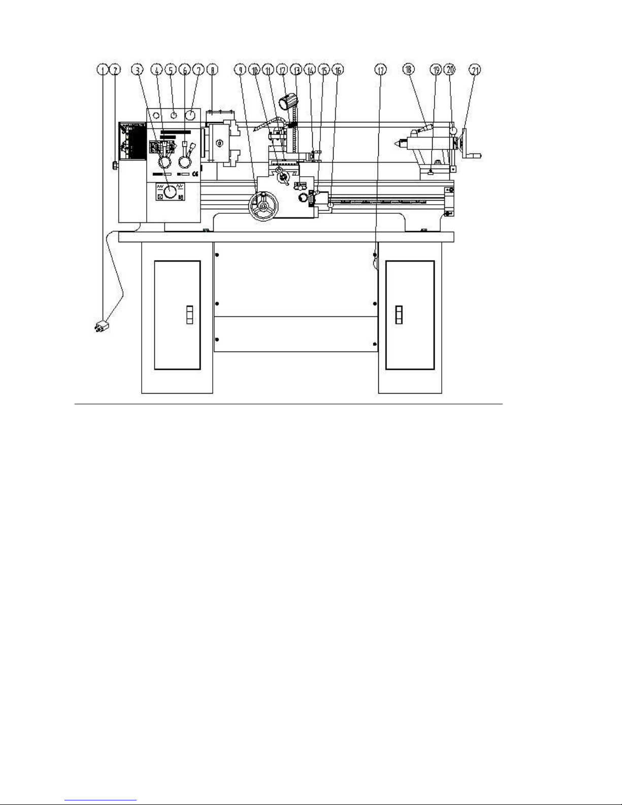
14
Fig 6.Operation Parts Fig.
1. Power source-plug
2. Transmission Box Cover
3. Forward/Reverse Switch for lead screw-Middle position is
Neutral
4. Shift Knob-Gear change
5.
6. Shift Knob-Gear change
7. Stop button
8. Chuck
9. Longitudinal-Feed hand wheel
10. Small Carriage Cross Feed hand wheel

15
11. Tool Post Swivel Nut
12. Tool Post feed hand wheel
13. Auto Feed for Tool Post-Left, Right, Neutral
14. Tool Carriage hand wheel
15. Carriage Auto-Feed Switch
16. START Forward/Reverse Switch
17. Pump Switch
18. Handle Lock for tailstock center
19. Offset Screw
20. Lever to lock Tailstock
21. Tailstock hand wheel
Threading Chart
Please see the following diagram for reference to cutting
threads

16
Threading
Cutting threads can be performed by the manual use of the
change gears and handle 4&5(refer to Operating Controls)
Grounding Instructions
In the event of a malfunction or breakdown, grounding provides
the path of least resistance for electrical current and reduces the risk
of electrical shock. This tool is equipped with an electrical cord that
has an equipment grounding conductor and a grounding plug. The
plug MUST be plugged into a matching outlet that has been properly
installed and grounded in accordance with ALL local codes and
ordinances.
DO NOT MODIFY THE PLUG PROVIDED. If the provided plug will

17
not fit the electrical outlet, have the proper outlet installed by a
qualified licensed electrician.
IMPROPER CONNECTION of the equipment grounding
conductor can result in risk of electrical shock. The conductor wire
with the green insulation (with or without yellow stripes) is the
equipment-grounding conductor. If repair or replacement of the
electrical cord or cord or plug is required, DO NOT connect the
equipment grounding conductor to a live terminal.
If in doubt about these instructions consult a qualified,
licensed electrician.
USE ONLY A THREE-WIRE EXTENSION CORD with a 3-prong
grounding plug and three-hole receptacles that accept the tool’s
plugs as shown.

18
Parts Listing-Lathe Head
No.
SPINDLE BOX
1
V710 GB/T1171-1986
V-belt type 680
皮带
2
M16*1.5 GB/T812-1988
Spanner nut
圆螺母
3
16 GB/T858-1988
Lock washer for circular nut
止动垫圈
4
BT1324&BT1330-02-031
Spindle pulley
皮带轮
5
30 GB/T894.1-1986
Circlips for shaft-type A
轴用挡圈
6
6206/P6 GB/T276-1994
Taper roller oearing
深沟球轴承
7
M5*16 GB/T77-1985
Hexagon socket head screw
内六角螺栓
8
BT1324&BT1330-02-030
Pulley seat
皮带轮支承座
9
35.5*2.65 GB/T3452.1-1992
O-seal ring
O型密封圈
10
FB016030 GB/T13871-1992
Felt coller
骨架橡胶密封圈
11
M6*8 GB/T818-1985
Crossrecessed pan head screws
十字盘头螺钉
12
6 GB/T97.1-1985
Plain washers
平垫圈
13
BT1324&BT1330-02-005
Lathe head
主轴箱
14
BT1324&BT1330-02-021
Nut
螺母
15
BT1324&BT1330-02-022
Felt coller
密封圈
16
BT1324&BT1330-02-020
Oil Screw
排油螺栓
17
BT1324&BT1330-02-058
Washer
橡胶垫圈

19
18
6 GB/T7940.4-1995
Oil cup
油杯
19
11 GB/T894.1-1986
Circlips for shaft-type A
轴用挡圈
20
BT1324&BT1330-02-040
coller
挡圈
21
BT1324&BT1330-02-039
Change Gear
挂轮 C
22
BT1324&BT1330-02-042
Sleeve spacer
隔套 D
23
A5*36 GB/T1096-1994
Plain parallel key
平键
24
BT1324&BT1330-02-041
Sleeve
衬套 B
25
BT1324&BT1330-02-038
Change Gear
挂轮 B
26
BT1324&BT1330-02-043
Shaft
芯轴
27
9*1.8 GB/T3452.1-1992
O-seal ring
O型密封圈
28
M5*8 GB/T71-1985
Screw
开槽锥端紧定螺钉
29
BT1324&BT1330-02-052
Block
拨块 A
30
M8*20 GB/T77-1985
Hexagon socket head screw
内六角螺栓
31
A6*30 GB/T117-1986
Taper pins
圆锥销
32
BT1324&BT1330-02-019
Adjust block
调整压板
33
M8*25 GB/T77-1985
Hexagon socket head screw
内六角螺栓
34
M8*10 GB/T77-1985
Set screws with cone point
内六角平端紧定螺
钉
35
0.8*5*20 GB/T2089
Spring
压缩弹簧
36
6 GB/T308-1989
Steel ball
钢球
37
BT1324&BT1330-02-004
Handle seat
手柄座
38
GB/T117-1986
Taper pins
圆锥销
39
M5*16 GB/T819-1985
Screw
十字槽沉头螺钉
40
BT1324&BT1330-02-009
Localing sleeve
转向座
41
BT1324&BT1330-02-057
Washer
垫圈
42
11.2*2.65 GB/T3452.1-1992
O-seal ring
O型密封圈
43
BT1324&BT1330-02-055
External snap ring
拨块 B
44
A10 JB/T9741.2
Oil Sight
油标
45
M10*30 GB/T77-1985
Hexagon socket head screw
内六角螺栓
46
BT1324&BT1330-02-003
Handle lever
手柄杆
47
AM8*40 JB/T7271.3-1994
Knob
手柄套
48
BT1324&BT1330-02-050
Sleeve
压盖 E
49
BT1324&BT1330-02-018
Washer
垫圈
50
12 GB/T894.1-1986
Circlips for shaft-type A
轴用挡圈
51
BT1324&BT1330-02-053
Shifting fork shaft
导向滑杆
52
BT1324&BT1330-02-055
Right shifting fork
拨叉 B
53
BT1324&BT1330-02-010
Sleeve
压盖 A
54
M10 GB/T41-1986
Nut
螺母
55
10 GB/T97.1-1985
Plain washers
平垫圈
56
BT1324&BT1330-02-033
Gear change
挂轮 A
57
FB016030 GB/T13871-1992
Felt coller
骨架橡胶密封圈
58
BT1324&BT1330-02-034
Sleeve
压盖 D
59
BT1324&BT1330-02-018
Washer
垫圈
60
6203/P6 GB/T276-1994
Taper roller oearing
深沟球轴承
61
A4*10 GB/T1096-1994
Plain parallel key
平键

20
62
BT1324&BT1330-02-044
Output shaft
输出轴
63
A5*60 GB/T1096-1994
Plain parallel key
平键
64
BT1324&BT1330-02-045
Gear
齿轮
65
BT1324&BT1330-02-046
Gear
齿轮
66
BT1324&BT1330-02-048
Gear
齿轮
67
BT1324&BT1330-02-049
Sleeve spacer
隔套 E
68
BT1324&BT1330-02-023
Sleeve
压盖 B
69
BT1324&BT1330-02-032
Sleeve
压盖 C
70
BT1324&BT1330-02-011
Sleeve spacer
隔套 A
71
A5*22 GB/T1096-1994
Plain parallel key
平键
72
BT1324&BT1330-02-017
Gear
齿轮
73
BT1324&BT1330-02-016
Gear
齿轮
74
BT1324&BT1330-02-015
Gear
齿轮
75
42 GB/T894.1-1986
Circlips for shaft-type A
轴用挡圈
76
22 GB/T894.1-1986
Circlips for shaft-type A
轴用挡圈
77
BT1324&BT1330-02-014
Middle shaft
滑移轴
78
6*4*10 GB/T1566-1990
Thin flat key
薄形平键
79
BT1324&BT1330-02-012
Gear
齿轮
80
BT1324&BT1330-02-013
Gear
齿轮
81
M50*1.5 GB/T812-1988
Spanner nut
圆螺母
82
50 GB/T858-1988
Lock washer for circular nut
圆螺母用止动垫圈
83
M5*20 GB/T77-1985
Hexagon socket head screw
内六角螺栓
84
BT1324&BT1330-02-036
Sleeve
后端盖
85
BT1324&BT1330-02-037
Pressurize washer
后端盖垫圈
86
BT1324&BT1330-02-035
Sleeve spacer
衬套 A
87
32010/P6X GB/T276-1994
Taper roller oearing
圆锥滚子轴承
88
55 GB/T894.1-1986
Circlips for shaft-type A
轴用挡圈
89
BT1324&BT1330-02-047
Gear
齿轮
90
32012/P5 GB/T276-1994
Taper roller oearing
圆锥滚子轴承
91
BT1324&BT1330-02-007
Pressurize washer
前端盖垫圈
92
BT1324&BT1330-02-006
Mainshaft bearing oil seal
前端盖
93
BT1324&BT1330-02-008
Lathe spindle
主轴
94
A8*16 GB/T1096-1994
Plain parallel key
平键
95
BT1324&BT1330-02-029
Sleeve spacer
隔套 C
96
BT1324&BT1330-02-028
Gear
齿轮
97
BT1324&BT1330-02-026
Sleeve spacer
隔套 B
98
BT1324&BT1330-02-027
Gear
齿轮
99
BT1324&BT1330-02-025
Gear
齿轮
100
A5*10 GB/T1096-1994
Plain parallel key
平键
101
A5*70 GB/T1096-1994
Plain parallel key
平键
102
BT1324&BT1330-02-024
Spingle shaft
输入轴
103
M8*30 GB/T77-1985
Hexagon socket head screw
内六角螺栓
104
BT1324&BT1330-02-002
Oil port plug
螺钉
105
BT1324&BT1330-02-001
Transmission cover
箱盖
106
28 GB/T894.1-1986
Circlips for shaft-type A
轴用挡圈
This manual suits for next models
1
Table of contents
Other Bolton Tools Lathe manuals


