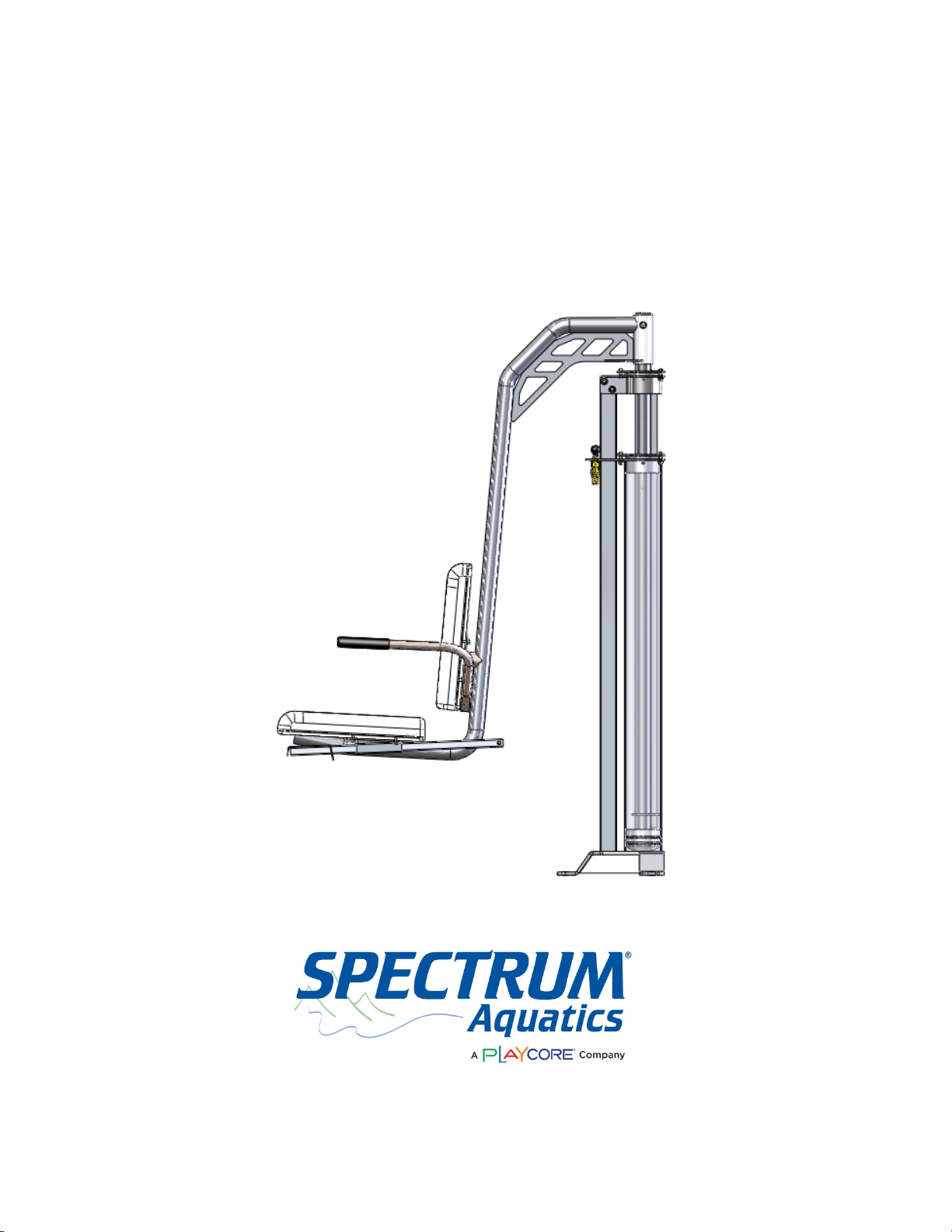
Playcore Spectrum Aquatics Summit WP 400 User manual

Summit WP 400
Part Number 42440
7100 Spectrum Lane ~ Missoula MT 59808
800.791.8056 ~ www.spectrumproducts.com
42440 Man Rev A

You have purchased a Spectrum Products Swim Lift®Summit WP 400. Providing the unit is
installed correctly and properly maintained, it will furnish you with many years of trouble free
use. It is important to read this entire manual prior to beginning assembly or operation.
Shipping Information:
Each lift should arrive fully assembled on a single pallet. Before accepting the shipment from
the carrier, inspect for visible damage and match the contents with those listed below.
Spectrum is not responsible for lost or damaged freight.
The Pallet will contain all structural components and hardware. The following is a list of the
components included with your shipment from Spectrum. Use Components and Hardware
Figure, page 2, as a reference to identify each item listed.
1
Assembled Summit Lift
1
Mounting Hardware
2
Seat Halves
2
Arm Rests (1 Each Right and Left)
1
800.791.8056 ▪www.spectrumproducts.com

Components and Hardware
2
800.791.8056 ▪www.spectrumproducts.com

Installation Overview
Read all instructions before attempting to assemble or install the Lift.
Anchor Location
It is recommended that the Summit be installed in or near the shallow end of the pool with
sufficient deck space and operational area in the pool as shown in Figure 1. For reasons of
safety and ADA guidelines, the lift must be installed in a location that is clear from obstacles and
other hazards.
NOTE: Do not locate the lift in a corner or directly adjacent to pool ladders/handrails or grab rails
that could interfere with the rotation of the lift. Do not place the lift where it may be cumbersome
or hazardous to any pool users.
Figure 1
Because the lift can be stopped at any position during lowering, there is no minimum pool depth
requirement for the Summit. However, to comply with ADA guidelines, the Summit must be
installed at a pool depth no greater than 48-inches and the seat should submerge to a minimum
depth of 18” below the surface of the water. There must be at least 6” from the center of each
anchor to the nearest joint, crack, curb or similar concrete structure to ensure the strength of the
concrete.
In addition, all installations should be in accordance with the ADA guidelines (ADA guidelines
are available at the website www.access-board.gov).
Anchor Installation
1. Mark the location of each anchor on the deck and use a 1” diameter concrete drill bit to drill
a 2 1/4” deep hole at each location. Make sure to drill straight down.
2. Clean all debris from hole and place the expansion anchor into the hole. Tap the anchor into
the hole until the top of the anchor is flush with the deck.
3
800.791.8056 ▪www.spectrumproducts.com

3. Set the expansion anchor at the bottom of the anchor hole by tapping the anchor pin with
the supplied ¼” diameter set tool rod with a hammer.
4. Locate a bonding source to bond (ground) the anchor. The steel rebar-bonding grid of the
pool deck is the best choice for bonding the anchor. Spectrum recommends using a bonding
strip to connect the anchor to one of the anchor bolts. Ensure that bonding meets all state
and local requirements.
NOTE: Article 680 of the National Electrical Code requires bonding of all metallic components in
relationship to pools and spas.
Lift Assembly
1. Attach the Lifting Cylinder to the Seat arm using a 3/8" x 3" Button Head screw, two 3/8" flat
washers, one 3/8" lock washer and a 3/8" acorn nut.
2. Attach the Rotationally molded Seat halves to the Seat arm using eight 5/16" x 1" Button
head screws, 5/16" washers and 5/16" lock washers. Make sure to attach the seatbelt using
the rear holes on the bottom seat half.
3. Connect footrest using one button head socket screw 1/4" x 1/2" and one 1/4" lock washer.
4. Place the two armrests into the seat frame behind the seat back, if the armrests do not look
parallel to the plane of the seat, switch them.
5. Connect the water supply to the female garden hose coupling on the control valve. Cut the
exhaust line to length making sure it is plumbed to an appropriate drain. After purging the
air from the cylinder, the Summit Lift is ready for operation.
.
4
800.791.8056 ▪www.spectrumproducts.com

Lift Operation
WARNING! Read all operating instructions before operating the lift. Make sure that all
individuals using the lift have read the instructions and have been made aware of all safety
precautions.
WARNING! Do not exceed the maximum lifting capacity of 400 lbs (181.4 kg). This may result in
damage to the lift or personal injury. Other lift models are available for loads in excess of 400
lbs.
The Swim-Lift® Summit is a water-powered lifting aid designed for use with water systems that
have a 55 PSI rating. This lift will function with as little as 45 PSI water pressure. Optional
pump kits are available for supplying a constant pressure of 55 PSI. Lifting capacities are
based on a continual pressure supply without pressure drops occasionally incurred during peak
demand periods of city water systems. The lifting capacity/pressure ratios are as follows:
Pressure Lift Capacity
55 PSI 400 lbs.
50 PSI 350 lbs.
45 PSI 300 lbs.
Note: A backflow check valve may be required on this lift to prevent contamination of the
municipal water supply. Please check your state and local codes to see if a backflow check
valve is required.
Lift Preparation:
1. Turn the control valve to the intermediate stop position and attach the water supply hose to
the valve. Turn the water supply on.
2. With no weight on the chair, turn the control valve handle to the up position. Allow the chair
to fully rise.
3. Turn the control valve handle to the down position. Allow the seat to lower to a fully down
position. Repeat steps 2 and 3 until a smooth operation is attained. This process purges
the air from the system and should not take more than 5 to 7 cycles to complete.
Lift Operation:
1. Lift operation is controlled through the use of the control valve. The valve handle turned
clockwise will lower the chair, and turned counter-clockwise will raise the chair. The chair
will stop at any point along its travel if the valve handle is turned to an intermediate position.
Excessive force is not required to turn the valve handle. Instruct all operators on proper use
of the control valve prior to operation of the lift.
2. The outer chair arm flips up and back for ease of transfer from a wheelchair to the lift seat.
In addition, the stationary arm on the inside of the chair may assist in transferring. Use of
the seatbelt is recommended for all users. To facilitate safe loading and unloading of
5
800.791.8056 ▪www.spectrumproducts.com

inexperienced users, we recommend that an attendant always be present. Instruct all
operators on the proper use of the chair features and the transfer procedure.
3. A lock pin is attached to the top of the cylinder to lock the chair in the fully raised position or
rotated 180° over the pool. Push the pin through the piston rod (lower hole) to lock the chair
in the fully raised position when the lift is not in use and/or when the water supply is turned
off. Use the 180° rotated lock pin hole (upper hole) to lock the chair in place when removing
the lift from the anchors.
4. To drain the water from the lift for storage: disconnect the water source, turn the control
valve to down, push the chair down, turn the control valve to up, and push the chair back up.
Repeating this step is necessary to get all of the water removed. This process will force the
water from the cylinder, valve and hoses.
6
800.791.8056 ▪www.spectrumproducts.com

Care and Maintenance
The following should be performed periodically to ensure safe and dependable use.
1. Remove any discoloration with a 3M scratch pad (stainless steel components only). Wipe
clean with a sponge dampened with Spectra Clean. Repeat these steps several times to
passivate the stainless steel. Spectra Clean kits are available from Spectrum (Part Number
202050-00). Do not spray with high-pressure water, only clean with non-chlorinated water.
2. Check all water connections – Check any external hoses for wear and/or breakage in the
outer tubing.
3. Check all mechanical connections – inspect the Nylock Nuts on all moving parts and make
sure they are snug.
7
800.791.8056 ▪www.spectrumproducts.com

Troubleshooting
Problem:
Cause:
Solution:
1. Lift will not operate at all:
Unit Not Level
Valve Failure
Kinked Hose
Air in Cylinder
Dirty Cylinder
Worn Top Collar
Check for level and shim
accordingly
Replace Valve (P/N 27285,
27286)
Un kink hose and recheck
Run unit 5-7 times up and down
while assisting motion
Call for assistance
Replace Top Collar (P/N
27315)
2. Lift chatters when moving.
Air in Cylinder
Dirty Cylinder
Worn Top Collar
Run unit 5-7 times up and down
while assisting motion
Call for assistance
Replace Top Collar (P/N
27315)
3. Lift moves up slowly
Low water pressure
Worn Seals
Valve Failure
Use lift with Booster Pump (P/N
27028-00)
Replace Seals (P/N 27245,
27246)
Replace Valve (P/N 27285,
27286)
4. The seat travels much slower
than normal.
Low battery
Defective or worn-out
battery
Recharge battery
Replace battery*
5. Lift descends with valve in
neutral position
Valve Failure
Worn Seals
Replace Valve (P/N 27285,
27286)
Replace Seals (P/N 27245,
27246)
*Please contact your local distributor or Spectrum Customer Service to order parts 406.532.6321
8
800.791.8056 ▪www.spectrumproducts.com
Table of contents
Popular Lifting System manuals by other brands

Novoferm
Novoferm NovoDock L340 Translation of the original assembly instruction

Forch
Forch 4915 20 instruction manual

Sky Climber
Sky Climber Rolling Roof Rig Assembly instructions

Ravaglioli
Ravaglioli RAV635 MOT4 manual

GCE druva
GCE druva MM40 Instructions for use

Vulcan-Hart
Vulcan-Hart VPT Operator's manual