Bomag BW 211 D-4 User manual
Service - Manual
Catalogue number.
008 911 45 01/2007
BW 211 D-4 / PD-4
BW 213 D-4 / PD-4
S/N 101 582 40 .....> S/N 101 582 41 .....> S/N 101 582 45 .....>
S/N 101 582 46 ....> S/N 101 582 50 ....>
Single drum roller


Table of Contents
BOMAG 3008 911 45
General 7
1.1 Introduction 8
1.2 Safety regulations 9
1.3 General repair instructions 14
1.4 Tightening torques 24
Technical data 29
2.1 Technische Daten 30
2.2 Maintenance chart 38
2.3 Table of fuels and lubricants 40
2.4 Fuels and lubricants 40
Connection overview 43
3.1 Connection overview 44
Tests and adjustments 47
4.1 Special tools, tests and adjustments 48
4.2 Checking the rotation speeds 52
4.3 Checking / adjusting the neutral positions of the travel pump 54
4.4 Pressure tests in the travel circuit 56
4.5 Checking / adjusting the vibrator shaft speeds 58
4.6 Pressure measurements in the vibration circuit 59
4.7 Check the leakage rate of the vibration motor 60
4.8 Pressure test in steering circuit 61
Flushing and bleeding 63
5.1 Special tools for flushing 64
5.2 Flushing - general 69
5.3 Flushing schematic travel circuit (distribution travel pump) 71
5.4 Flushing the travel circuit (travel pump distribution) 73
5.5 Flushing schematic travel circuit (distribution axle motor) 79
5.6 Flushing the travel circuit (axle motor distribution) 84
5.7 Flushing schematic for vibration drive 89
5.8 Flushing the vibration circuit 90
5.9 Bleeding the travel circuit 94
5.10 Bleeding the vibration circuit 96
Fundamental electrics 99
6.1 Understanding circuit diagrams 100
6.2 Terminal designations 104
6.3 Current and voltage 108
6.4 Resistance 112
6.5 Series / parallel connection 114
6.6 Ohm's law 116
6.7 Electrical energy 116
6.8 Formula diagram 117
6.9 Metrology 118
6.10 Diodes, relays, fuses 120
6.11 Batteries 123
6.12 Three-phase generator 126
6.13 Electric starter 133
Find manuals at https://best-manuals.com

Table of Contents
BOMAG4008 911 45
6.14 Telemecanique switch 136
6.15 Inductive proximity switches 139
6.16 Angle sensor with current output 140
6.17 Plug connectors 141
6.18 Deutsch plug, series DT and DTM 142
6.19 Plugs and terminals in spring clamping technology 148
Special tools, electrics 153
7.1 Special tools, electrics 154
Electronic modules 163
8.1 Seat contact module 165
Speedometer Module 173
9.1 Speedometer module 175
Service Training 177
10.1 Electrics BEM (BOMAG Evib-meter) 179
10.2 Service Training 237
Engine 299
11.1 Diesel engine, general 301
11.2 Service side 302
11.3 Starter side 303
11.4 Lubrication oil circuit 304
11.5 Oil pressure switch and low oil pressure circuitry 306
11.6 Check the engine oil level 307
11.7 Changing engine oil and oil filter cartridges 308
11.8 Coolant circuit 310
11.9 Coolant temperature switch 312
11.10 Disassembling and assembling the coolant temperature switch 313
11.11 Replacing the thermostat 314
11.12 Checking the thermostat in disassembled state 315
11.13 Check the coolant level 316
11.14 Change the coolant 316
11.15 Clean the cooling fins on engine and hydraulic oil cooler 317
11.16 Three-phase generator 318
11.17 Fuel supply 320
11.18 Injection system 323
11.19 Injection pump replacement during service 324
11.20 Injection valve replacement during service 333
11.21 Checking / repairing injection valves 336
11.22 Fuel filter 341
11.23 Check, clean the water separator 343
11.24 Change the fuel pre-filter cartridge 343
11.25 Change the fuel filter cartridge 344
11.26 Checking the compression 345
11.27 Check, adjust the valve clearance 346
11.28 Boost fuel solenoid valve 348
11.29 Engine shut-down solenoid 349
11.30 Air filter, differential pressure switch 350
11.31 Service the combustion air filter 351
Find manuals at https://best-manuals.com

Table of Contents
BOMAG 5008 911 45
11.32 Heating flange on engine 354
11.33 Checking the heating flange control 357
11.34 Electric throttle control 358
11.35 Engine monitoring 360
11.36 Engine 363
11.37 Special tools, Deutz engine (BFM 2012) 365
Air conditioning system 377
12.1 Physical basics 379
12.2 Refrigerant R134a 382
12.3 Compressor oil / refrigeration oil 383
12.4 Working principle of the air conditioning system 384
12.5 Monitoring devices 384
12.6 Description of components 385
12.7 Checking the compressor oil level 391
12.8 Checking the magnetic clutch 392
12.9 Inspection and maintenance work 393
12.10 Checking, replacing the refrigerant compressor V-belt 393
12.11 Service the air conditioning 394
12.12 Drying and evacuation 397
12.13 Emptying in case of repair 397
12.14 Leak test 398
12.15 Filling instructions 399
12.16 Trouble shooting in refrigerant circuit, basic principles 402
12.17 Trouble shooting, refrigerant circuit diagram 406
12.18 Trouble shooting procedure 407
12.19 Steam table for R134a 417
12.20 Heating control / air conditioning control 423
Replacing the cab window panes 429
13.1 Assembly of window panes 430
13.2 Special tools 431
13.3 Auxiliary materials 432
13.4 Removing and installing the window pane 434
Drum 439
14.1 Special tools, drum, single drum rollers 440
14.2 Repair overview for drum 442
14.3 Removing and installing the drum 450
14.4 Repairing the drum 456
14.5 Dismantling, assembling the change-over weights 489
14.6 Changing the rubber buffers and adjusting the pretension 492
Oscillating articulated joint 495
15.1 Special tools 496
15.2 Repair overview oscillating articulated joint 498
15.3 Removing and installing the oscillating articulated joint 501
15.4 Dismantling the oscillating articulated joint 503
15.5 Assembling the oscillating articulated joint 508
Suppliers documentation 519
16.1 Travel pump series 90R 521
Find manuals at https://best-manuals.com

Table of Contents
BOMAG6008 911 45
16.2 Travel drive series 51 611
16.3 Vibration pump 42R 041 693
16.4 Vibration motor A10FM 731
16.5 MS/MSE 02 ..... 18 755
16.6 Axle DANA 192 805
Circuit diagrams 929
17.1 Wiring diagram 931
17.2 Wiring diagram 955
17.3 Wiring diagram 985
17.4 Hydraulic diagram 1021
Find manuals at https://best-manuals.com


1.1 Introduction
BOMAG8008 911 45
1.1 Introduction
This manual is intended to support expert mechanics
in efficient repair and maintenance work. Whoever
wants to do repair work himself should have been suf-
ficiently trained and posses profound expert knowl-
edge, he should limit his work only to those parts and
components which will not affect the safety of the ve-
hicle or the passengers. It is highly recommended to
have repairs to critical systems, such as steering,
brakes and travel drive, sole carried out by a BOMAG
workshop. Untrained persons should NEVER UN-
TERTAKE SUCH REPAIR WORK.
The repair instructions describe the removal or dis-
mantling and assembly of components and assembly
groups. The repair of disassembled assembly groups
is described as far as this makes sense with respect
to available tools and spare parts supply and as far as
it can be understood by a skilled mechanic.
Documentation
For the BOMAG machines described in this training
manual the following documentation is additionally
available:
1 Operating and maintenance instructions
2 Spare parts catalogue
3 Wiring diagram*
4 Hydraulic diagram*
5 Service Information
You should only use genuine BOMAG spare parts.
Spare parts needed for repairs can be taken from the
spare parts catalogue for the machine.
This manual is not subject of any updating service; we
would therefore like to draw your
attention to the additionally published "technical serv-
ice information".
In case of a new release all necessary changes will be
included.
In the course of technical development we reserve the
right for technical modifications without prior notifica-
tion.
Information and illustrationsin this manual must not
be reproduced and distributed, nor must they be used
for the purpose of competition. All rights according to
the copyright law remain expressly reserved.
!Danger
Please observe strictly the safety regulations in
this manual, in the operating instructions as well
as the applicable accident prevention regulations.
BOMAG GmbH
Printed in Germany
Copyright by BOMAG
* The applicable documents valid at the date of print-
ing are part of this manual.
Find manuals at https://best-manuals.com

Safety regulations
BOMAG 9008 911 45
1.2
1.2 Safety regulations
Important notes
These safety regulations must be read and ap-
plied by every person involved in the repair of this
machine. The applicable accident prevention in-
structions and the safety regulations in the oper-
ating and maintenance instructions must be
additionally observed.
Repair work shall only performed by appropriately
trained personnel or by the after sales service of
BOMAG.
Any suggestions, safety precautions and warn-
ings in this section are intended as a mnemonic
aid for well trained and experienced expert me-
chanics. This manual should not be considered a
bible on workshop safety.
Workshop equipment and facilities as well as the
use and waste disposal of solvent, fluids, gases
and chemicals are subject to legal regulations,
which are intended to provide a minimum on safe-
ty. It is obviously your own responsibility to know
and adhere to these regulations.
This manual contain headers like "Note", "Attention",
"Danger" and "Environment", which must be strictly
complied with in order to avoid dangers for health and
for the environment.
!Danger
Paragraphs marked like this highlight possible
dangers for persons.
!
Caution
Paragraphs marked like this highlight possible
dangers for machines or parts of the machine.
i
Note
Paragraphs marked like this contain technical infor-
mation for the optimaleconomical use of the machine.
Environment
Paragraphs marked like this point out practices
for safe and environmental disposal of fuels and
lubricants as well as replacement parts.
Observe the regulations for the protection of the
environment.
General
lBefore starting repair work stand the machine on
level and solid ground.
lAlways secure the machine against unintended roll-
ing.
lSecure the engine reliably against unintentional
starting.
lMark a machine that is defective or being repaired
by attaching a clearly visible warning tag to the
steering wheel.
lOn machines with articulated joint keep the articu-
lated joint locked during work.
lUse protective clothes like hard hat, safety boots
and gloves.
lKeep unauthorized persons away from the machine
during repair work.
lTools, lifting gear, lifting tackle, supports and other
auxiliary equipment must be fully functional and in
safe condition.
lUse only safe and approved lifting gear of sifficient
load bearing capacity to remove and install parts or
components from and to the machine.
lBe careful with cleansing agents. Do not use easily
inflammable or harmful substances, such as gaso-
line or paint thinners for cleaning.
lCleaning or repair work on the fuel tank is very dan-
gerous. Do not smoke or allow any ignitable sparks
or open fire in the vicinity when cleaning or repairing
a tank. .
lWhen performing welding work strictly comply with
the respective welding instructions.
Precautions and codes of conduct for
welding work
Welding work should only be performed by specially
instructed expert personnel.
!Danger
Electric shock!
Sparks, fire hazard, burning of skin!
Infrared or ultraviolet radiation (arc), flashing of
eyes!
Health hazard caused by welding work on highly
alloyed work pieces, metal coatings, paint coat-
ings, plastic coatings, oil containing dirt deposits,
grease or solvent residues, etc.!
lCheck welding equipment and cables for damage
before use (also the validity of inspection stickers).
lEnsure good conductivity between earth cable and
work piece.
lStart the extraction fan before starting work and
guide with the progressing work as required.
lAlways isolate the burner when laying it down (re-
move possible electrode residues).
lProtect cables from being damaged, use cables
with insulated couplings.
lEnsure sufficient fire protection, keep a fire extin-
guisher at hand.
Find manuals at https://best-manuals.com

1.2 Safety regulations
BOMAG10 008 911 45
lIn case of welding work in fire or explosion endan-
gered environments, you should always ask for a
welding permission.
lRemove combustible parts from the vicinity or cover
such parts.
lName a fire watch during and after welding work.
lDo not clamp the welding rod holder and the inert
gas welding gun under your arm and lay these parts
only on an insulated top.
lPlace the inert gas bottles in a safe place and se-
cure them against falling over.
lUse a protective screen or an arcing shield with
welding glass, wear welding gloves and clothes,
this applies also for assisting persons.
lSwitch the welding unit off before connecting weld-
ing cables.
Behaviour in case of faults
lCheck electrode holders and electric cables at reg-
ular intervals.
lIn case of deficiencies switch off the welding unit
and inform supervising persons.
lIn case of an extractor fan failure or any other fault
inform the supervising persons.
Maintenance; waste disposal
lReplace damaged insulating jaws and welding rod
holders immediately.
lReplace the welding wire reels only in deenergized
state.
What to do in case of accidents; First Aid
lKeep calm.
lCall first air helpers.
lReport the accident.
lIn case of an electric accident: Interrupt the power
supply and remove the injured person from the
electric circuit. If breathing and heart have stopped
apply reactivation measures and call for an emer-
gency doctor.
Old oils
Prolonged and repetitive contact with mineral oils will
remove the natural greases from the skin and causes
dryness, irritation and dermatitis. Moreover, used en-
gine oils contain potentially hazardous contaminants,
which could cause skin cancer. Appropriate skin pro-
tection agents and washing facilities must therefore
be provided.
lWear protective clothes and safety gloves, if possi-
ble.
lIf there is a risk of eye contact you should protect
your eyes appropriately, e.g. chemistry goggles or
full face visor; a facility suitable for rinsing the eyes
should also be available.
lAvoid prolonged and repetitive contact with oil, es-
pecially with old oil. In case of open incisions and in-
juries seek medical advice immediately.
lApply protective cream before starting work, so that
oil can be easier removed from the skin.
lWash with soap and water to ensure that all oil has
been removed (a skin cleaning agent and a nail
brush will help). Lanolin containing agents will re-
place natural skin oils that were lost.
lDo not use gasoline, kerosene, diesel, thinner or
solvents to wash the skin.
lDo not put oil soaked cloths into your pockets.
lAvoid clothes, especially underpants, getting soiled
by oil.
lOveralls must be washed at regular intervals.
Clothes that cannot be washed, must be disposed
of.
lIf possible degrease components before handling.
Environment
It is strictly prohibited to drain off oil into the soil,
the sewer system or into natural waters. Entrust
special companies with the waste disposal of old
oil. If in doubt you should consult your local au-
thorities.
Hydraulics
lHydraulic oil escaping under pressure can pene-
trate the skin and cause severe injury. You should
therefore relieve the pressure in the system before
disconnecting any lines.
lBefore applying pressure to the system make sure
that all line connections and ports have been prop-
erly tightened and are in perfect condition.
lHydraulic oil leaking out of a small opening can
hardly be noticed, therefore please use a piece of
cardboard or wood when checking for leaks. When
being injured by hydraulic oil consult a physician im-
mediately, as otherwise this may cause severe in-
fections.
lDo not step in front of or behind the drums/wheels/
crawler tracks when performing adjustment work in
the hydraulic system while the engine is running.
Block drums and/or wheels / crawler tracks with
wedges.
Find manuals at https://best-manuals.com

Safety regulations
BOMAG 11008 911 45
1.2
Reattach all guards and safety installations after
all work has been completed.
Environment
It is strictly prohibited to drain off hydraulic oil
into the soil, the sewer system or into natural wa-
ters. Entrust special companies with the waste
disposal of old oil. If in doubt you should consult
your local authorities.
Fuels
!Danger
Repair work on fuel systems must only be per-
formed by appropriately trained personnel.
The following notes refer to general safety precau-
tions for danger free handling of fuel. These notes are
only general instructions; in case of uncertainties you
should consult the person responsible for fire protec-
tion.
Fuel vapours not only are easily inflammable, but also
highly explosive inside closed rooms and toxic; dilu-
tion with air creates an easily inflammable mixture.
The vapours are heavier than air and therefore sink
down to the ground. Inside a workshop they may eas-
ily become distributed by draft. Even the smallest por-
tion of spilled fuel is therefore potentially dangerous.
lFire extinguishers charged with FOAM, SCHAUM,
CO2 GAS or POWDER must be available wherever
fuel is stored, filled in, drained off, or where work on
fuel systems is performed.
lThe vehicle battery must always be disconnected,
BEFORE work in the fuel system is started. While
working on the fuel system you should not discon-
nect the battery, because this could generate
sparks, which would ignite explosive fuel vapours.
lWherever fuel is stored, filled, drained off or where
work on fuel systems is carried out, all potential ig-
nition sources must be extinguished or removed.
Search lights must be fire proof and well protected
against possible contact with running out fuel.
Hot fuels
Before draining fuel off the tank for repair work, you
must strictly apply the following measures:
lAllow the fuel to cool down, to prevent any contact
with a hot fluid.
lVent the system, by removing the filler cap in a well
ventilated area. Screw the filler cap back on, until
the tank is finally emptied.
Synthetic rubber
Many O-rings, hoses and similar parts, which are ap-
parently made of natural rubber, are actually made of
plastic material, a so-called fluoroelastomer. Under
normal operating conditions this material is safe and
does not impose any danger to health.
However, if this material becomes damaged by fire or
extreme heat, it may decompose and form highly
caustic hydrofluoric acid, which can cause severe
burns in contact with skin.
lIf the material is in such a state it must only be
touched with special protective gloves. These
gloves must be disposed of directly after use.
lIf the material has contacted the skin despite these
measures, take off the soiled clothes and seek
medical advice immediately. In the meantime wash
the affected parts of the skin for 15 to 60 minutes
with cold water or lime water.
Poisonous substances
Some of the fluids and substances used are toxic and
must under no circumstances be consumed.
Skin contact, especially with open wounds, should be
strictly avoided.
These fluids and substances are, amongst others,
anti-freeze agents, hydraulic oils, washing additives,
lubricants and various bonding agents.
Air conditioning system
!
Caution
Lines in the air conditioning system must only be
loosened by trained and explicitly instructed ex-
perts.
lWear safety goggles! Put on your safety goggles.
This will protect your eyes against coming into con-
tact with refrigerant, which could cause severe
damage by freezing.
lWear safety gloves and an apron! Refrigerant are
excellent solvents for greases and oils. In contact
with skin they will remove the protective grease film.
However, degreased skin is very sensitive against
cold temperatures and germs.
lDo not allow liquid refrigerants to come into contact
with skin! Refrigerant takes the heat required for
evaporation from the environment. Very low tem-
peratures may bereached. The results may be local
frost injuries (boiling point of R134a -26.5°C at am-
bient pressure).
lDo not inhale higher concentrations of refrigerant
vapours! Escaping refrigerant vapours will mix with
the ambient air and displace the oxygen required for
breathing.
lSmoking is strictly prohibited! Refrigerants may be
decomposed by a glowing cigarette. The resulting
substances are highly toxic and must not be in-
haled.

1.2 Safety regulations
BOMAG12 008 911 45
lWelding and soldering on refrigeration equipment!
Before starting welding or soldering work on vehi-
cles, (in the vicinity
of air conditioning components) all refrigerant must
be drawn out and the rests removed by blowing out
the system with nitrogen. The decomposition prod-
ucts created from the refrigerant under the influence
of heat not only are highly toxic, but also have a
strong corrosive effect, so that pipes and system
components may be attacked. The substance is
mainly fluorohydrogen.
lPungent smell! In case of a pungent smell the afore
mentioned decomposition products have already
been created. Extreme care must be exercised not
to inhale these substances, as otherwise the respi-
ratory system, the lungs and other organs may be
harmed.
lWhen blowing out components with compressed air
and nitrogen the gas mixture escaping from the
components must be extracted via suitable exhaust
facilities (workshop exhaust systems).
Handling pressure vessels
lSince the fluid container is pressurized, the manu-
facture and testing of these pressure vessels is gov-
erned by the pressure vessel directive. (New edition
from April 1989). Paragraph 10 of the pressure ves-
sel directive demands that these pressure contain-
ers must be periodically inspected and tested by a
specialist, according to paragraph 32. In this case
periodically recurring inspections consist of external
examinations, normally on containers in operation.
The refrigerant container must be visually inspected
two times per year, within the frame work of major
inspections. Special attention must thereby be paid
to signs of corrosion and mechanical damage. If the
container is in no good condition, it should be re-
placed for safety reasons, in order to protect the op-
erator or third parties against the dangers when
handling or operating pressure vessels.
lSecure pressure vessels against tipping over or roll-
ing away.
lDo not throw pressure vessels. Pressure vessels
may thereby be deformed to such an extent, that
theywill crack. The suddenevaporation andescape
of refrigerant releases excessive forces. This ap-
plies also when snapping off valves on bottles. Bot-
tles must therefore only be transported with the
safety caps properly installed.
lRefrigerant bottles must never be placed near heat-
ing radiators. Higher temperatures will cause higher
pressures, whereby the permissible pressure of the
vessel may be exceeded. The pressure vessel di-
rective therefore specifies that a pressure vessel
should not be warmed up to temperatures above 50
°C.
lDo not heat up refrigerant bottles with an open
flame. Excessive temperatures can damage the
material and cause the decomposition of refriger-
ant.
lDo not overfill refrigerant bottles, since any temper-
ature increase will cause enormous pressures.
Environment
In operation, during maintenance and repair work
and when taking refrigeration systems our of
service it is not permitted to let refrigerant escape
into the atmosphere, which would contradict the
current status of technology.
Battery
lWear goggles and face protection (acid).
lWear suitable clothes to protect face, hands and
body (acid).
lWork and store accumulators only well ventilated
rooms. (Development of oxyhydrogen gas).
lDo not lean over the battery while it is under load,
being charged or tested. (Danger of explosion).
lBurning cigarettes, flames or sparks can cause ex-
plosion of the accumulator
lKeep ignition sources away from the battery.
lAlways shield eyes and face towards the battery.
lDo not use battery chargers or jump leads without
following the operating instructions.
lKeep the cell plugs closed.
lAfter an accident with acid flush the skin with water
and seek medical advice.
lDo not allow children access to batteries.
lWhen mixing battery fluid always pour acid into wa-
ter, never vice-versa.
Special safety regulations
lUse only genuine BOMAG spare parts for repair
purposes. Original parts and accessories have
been specially designed for this machine.
lWe wish to make explicitly clear that we have not
tested or approved any parts or accessories not
supplied by us. The installation and/or use of such
products may therefore have an adverse effect on
the specific characteristics of the machine and
thereby impair the active and/or passive driving
safety. The manufacturer explicitly excludes any li-
ability for damage caused by the use of non-original
parts or accessories.
lUnauthorized changes to the machine are prohibit-
ed for safety reasons.
lIf tests on the articulated joint need to be performed
with the engine running, do not stand in the articu-
lation area of the machine, danger of injury!

Safety regulations
BOMAG 13008 911 45
1.2
lDo not perform cleaning work while the engine is
running.
lIf tests must be performed with the engine running
do not touch rotating parts of the engine, danger of
injury.
lExhaust gases are highly dangerous. Always en-
sure an adequate supply of fresh air when starting
the engine in closed rooms.
lRefuel only with the engineshut down. Ensure strict
cleanliness and do not spill any fuel.
lKeep used filters in a separate waste container and
dispose of environmentally.
lDispose of oils and fuel environmentally when per-
forming repair or maintenance work.
lDo not refuel in closed rooms.
lDo not heat up oil higher than 160 °C because it
may ignite.
lWipe off spilled oil and fuel.
lDo not smoke when refuelling or when checking the
acid level in the battery.
lDo not check the acid level of the battery with a na-
ked flame, danger of explosion!
lOld batteries contain lead and must be properly dis-
posed of.
lThere is a danger of scalding when draining off en-
gine or hydraulic oil at operating temperature.
lon machines with rubber tires a tire may busr if in-
correctly assembled. This can cause severe injury.
lDo not exceed the specified highest permissible tire
pressure.

1.3 General repair instructions
BOMAG14 008 911 45
1.3 General repair instructions
General
lBefore removing or disassembling and parts, hoses
or components mark these parts for easier assem-
bly.
lBefore assembly oil or grease all parts, as far as this
is necessary.
Electrics
General
The electric and electronic systems in construction
equipment are becoming more and more extensive.
Electronic elements are increasingly gaining impor-
tance in hydraulic and mechanical vehicle systems.
Diagnostics according to plan
A structured approach in trouble shooting saves time
and helps to avoid mistakes and expenses, especially
in the fields of electrics and electronics. Understand-
ing electronic controls requires the knowledge of
some basic terms concerning their general perform-
ance. In many cases error logs are just simply read
out and control units are replaced without any further
trouble shooting. This is in most cases unnecessary
and, even more important, very expensive.
Random tests have revealed that purely electronic
components or control units only very rarely are the
actual cause of failures:
lIn approx. 10 % of the examined cases the prob-
lems were caused by control units.
lIn approx. 15 % sensors and actuators were the
cause of the problems.
By far the highest proportionof all faults could be
traced back to wiring and connections (plugs, etc.).
General:
lBefore changing any expensive components, such
as control units, you should run a systematic trouble
shooting session to eliminate any other possible
fault sources. Electric signals must be checked at
the locations to which they are applied, i.e. on con-
trol unit or sensor technology. So, if the system had
been diagnosed without unplugging the control unit
and checking the wiring, one should be alerted.
lCheck for good cable and ground contacts, there-
fore keep all mechanical transition points between
electric conductors (terminals, plugs) free of oxide
and dirt, as far as this is possible.
lPerform trouble shooting in a systematic way. Do
not become confused by the high number and vari-
ety of electric cables, current can only flow in a
closed circuit. You should first become acquainted
with the function of the corresponding electric circuit
by following the correct wiring diagram. Detected
faults should be rectified immediately. If the system
still does not work correctly after this measure, trou-
ble shooting must be continued. Several faults very
rarely occur at the same time, but it is not impossi-
ble.
lDo not disconnect or connect battery or generator
while the engine is running.
lDo not operate the main battery switch under load.
General repair instructions
BOMAG 15008 911 45
1.3
lDo not use jump leads after the battery has been re-
moved.
lSensors and electric actuators on control units must
never be connected individually or between exter-
nal power sources for the purpose of testing, but
only in connection with the control unit in question,
as otherwise there may be a risk of destruction
(damage)!
lDisconnecting the control unit plug connectors with
the control unit switched on, i.e. with the power sup-
ply (terminal 15 "On"), is not permitted. Switch the
voltage supply "off" first - then pull out the plug.
lEven with an existing polarity reversal protection in-
correct polarity must be strictly avoided. Incorrect
polarity can cause damage to control units!
lPlug-in connectors on control units are only dust
and water tight if the mating connector is plugged
on! Control units must be protected against spray
water, until the mating connector is finally plugged
on!
lUnauthorized opening of the control electronics (mi-
cro controller MC) as well as changes or repairs on
the wiring can lead to dangerous malfunctions.
lDo not use any radio equipment or mobile phones
inside the driver's cab without an appropriate out-
side antenna or in the vicinity of the control electron-
ics!
Electrical system and welding work
lSurge voltages in the electric system must be strict-
ly avoided:
lWhen performing welding work always fasten the
earth clamp of the welding unit in the immediate vi-
cinity of the welding location.
!
Caution
Switch off the main battery switch, doisconnect
the generator and pull the plug out on the control
unit before starting welding work.
Battery
Rules for the handling of batteries
Even though it may be conveniently installed in the
engine compartment, it should never be used as a rest
for tools. When connecting the poles, e.g. by means
of a spanner, the battery will become an "electric
welder".
As a measure to avoid short circuits you should first
disconnect the negative pole during disassembly and
reconnect the negative pole last during assembly.
Terminal clamps should be assembled with as little
force as possible.
Poles and terminal clamps should always be kept
clean to avoid transition resistances during starting
and the related development of heat.
You should obviously also pay attention to secure fas-
tening of the battery in the vehicle.

1.3 General repair instructions
BOMAG16 008 911 45
Hydraulic system
!
Caution
Do not open any hydraulic components if you
have not been properly trained and without exact
knowledge.
Please note
Cleanliness is of utmost importance. Make sure that
no dirt or other contaminating substances can enter
into the system.
lClean fittings, filler covers and the area around such
parts before disassembly to avoid entering of dirt.
lBefore disconnecting hoses, pipes or similar relieve
the system pressure with the engine shut down.
lDuring repair work keep all openings closed with
clean plastic plugs and caps.
lDo not run pumps and motors without oil.
lWhen cleaning hydraulic components take care not
to damage any fine machine surfaces.
lChemical and rubber soluble cleansing agents may
only be used to clean metal parts. Do not let such
substances come in contact with sealing material.
lRinse of cleaned parts thoroughly, dry them with
compressed air and apply anti-corrosion oil immedi-
ately. Do not install parts that show traces of corro-
sion.
lAvoid the formation of rust on fine machined caused
by hand sweat.
lGrease must not used as a sliding agent for assem-
bly work. Use hydraulic oil.
lDo not start the engine after the hydraulic oil has
been drained off.
lUse only the specified pressure gauges. Risk of
damaging the pressure gauges under too high pres-
sure.
lClean ports and fittings before removal so that no
dirt can enter into the hydraulic system.
lCheck the hydraulic oil level before and after the
work.
lUse only clean oil according to specification.
lCheck the hydraulic system for leaks, find and rec-
tify the cause.
lFill new hydraulic units with hydraulic oil before
starting operation.
lAfter changing a component thoroughly flush and
bleed the entire hydraulic system.
lPerform measurements at operating temperature of
the hydraulic oil (approx. 40 ¯C).
lAfter changing a component perform a high and
charge pressure test, if necessary check the speed
of the exciter shaft.
lThe operating pressure of the exciter shaft to a
great extent depends on the base under the vibrat-
ing drum. If the soil is too hard place the drums on
old rubber tires. Do not activate the vibration on a
hard, concreted base, danger of bearing damage.
lAfter the completion of all tests perform a test run
and then check all connections and fittings for leaks
with the engine still stopped and the hydraulic sys-
tem depressurized.
Before commissioning
lAfter changing a component clean the hydraulic oil
tank thoroughly.
lFill the housings of hydraulic pumps and motors
with hydraulic oil.
lUse only hydraulic oils according to the specifica-
tion in the maintenance instructions.
lAfter changing a component clean the hydraulic
system as described in the flushing instructions in
order to prevent all other components from being
damaged by abrasion and metal chips remaining in
the system.
lChange the hydraulic oil filter.
Commissioning
lBleed the hydraulic circuits.
lStart up the system without load.
lCheck the hydraulic oil level in the tank, fill up oil if
necessary.
After commissioning
lCheck system pressures and speeds.
lCheck fittings and flanges for leaks.
lAfter each repair check all adjustment data, rota-
tional speeds and nominal values in the hydraulic
system, adjust if necessary.
lDo not adjust pressure relief valves and control
valves to values above their specified values.

General repair instructions
BOMAG 17008 911 45
1.3
Air conditioning system
CFC - halon prohibition
The CFC - halon prohibition from May 06, 1991 regu-
lates the withdrawal from the use of CFC and the han-
dling of these refrigerants.
Contents:
Since 1995 CFC (R12) is no longer permitted for use
in new systems.
In operation, during maintenance and repair work and
when taking refrigeration systems our of service it is
not permitted to let refrigerant escape into the atmos-
phere, which would contradict the current status of
technology.
Work on refrigeration systems must only be carried
out by persons with well founded knowledge about
such systems and who have the necessary technical
equipment available.
The use of refrigerant must be documented.
Old systems should be converted to refrigerants
harmless to ozone (refrigerant substitutes).
For this reason the Federal Environmental Agency at
the end of 1995 published suitable replacement refrig-
erants for R 12. As a consequence old systems must
no longer be filled with R12. As soon as such a system
is opened for service, the system must be converted
to a suitable replacement or service refrigerant. Old
systems may still be used, as long as they are leak
tight. R 134a was nominated as replacement for R 12.
Inside the European Union the "EU-Directive 2037/
2000 on substances causing decomposition of the
ozone layer" regulates the production, use and avail-
ability of CFC and H-CFC.
lIn case of a repair on the refrigeration system you
should first evacuate the air conditioning system for
at least 45 minutes to remove any moisture from the
system, before you start to refill. Moisture bonded in
the compressor oil / refrigeration oil (PAG oil) can
only be removed from the system by changing the
oil.
lDuring repair work on refrigerant lines and compo-
nents, these must be kept closed as far as possible,
in order to prevent the invasion of air, moisture and
dirt,becausetheoperational reliability of the system
can only be assured if all components in the refrig-
erant circuit are clean and dry from inside.
lMake sure that no dirt or foreign parts can enter into
the compressor or the air conditioning system. The
area around the refrigerant hoses should be
cleaned with a gasoline free solvent.
lAll parts to be reused should be cleaned with a
gasoline free solvent and blow-dried with clean
compressed air or dried with a lint-free cloth.
lBefore opening all components should have
warmed up to ambient temperature, to avoid that
damp air is drawn into the component by the differ-
ence in temperatures.
lDamaged or leaking parts of the air conditioning
must not be repaired by welding or soldering, but
must generally be replaced.
lDo not fill up refrigerant, but extract existing refrig-
erant and refill the system.
lDifferent types of refrigerant must not be mixed.
Only the refrigerant specified for the corresponding
air conditioning system must be used.
lRefrigerant circuits with refrigerant type R134a
must only be operated with the compressor oil / re-
frigeration oil approved for the compressor.
lUsed compressor oil / refrigeration oil must be dis-
posed of as hazardous waste.
lDue to its chemical properties compressor oil / re-
frigeration oil must never be disposed of together
with engine or transmission oil.
lCompressor oil / refrigeration oil is highly hydro-
scopic. Oil cans must strictly be kept closed until
use. Oil rests should not be used, if the can had
been opened over a longer period of time.
lAll O-rings as well as pipe and hose fittings must be
oiled with compressor/refrigeration oil be-
foreiassembly.
lWhen replacing a heat exchanger, e.g. evaporator
or condenser, any compressor oil / refrigeration oil
lost by exchanging the components, must be re-
placed with fresh oil.
lA too high compressor oil / refrigeration oil level ad-
versely affects the cooling performance and a too
low oil level has a negative effect on the lifetime of
the compressor.
lIf a air conditioning unit needs to be opened, the
dryer must be replaced in any case.
lAlways use new O-rings when reassembling the
unit.
lAlways use two spanners when connecting pipes or
hoses, to prevent the pipe end from being damaged
.
lTighten screw fittings with the specified torque.
lCheck the connections of pipes, fittings or compo-
nents thoroughly; do not use if damaged.
lDo not leave the refrigerant circuit unnecessarily
open to the atmosphere. Do not attempt to repair
bent or burst pipes.
lCompressor valves must only be opened after the
system has been properly sealed.
lThe use of leak detection colouring matter is not
permitted, because its chemical composition is un-
known and its effect on compressor oil and rubber
elements is not predictable. The use of leak detec-

1.3 General repair instructions
BOMAG18 008 911 45
tion colouring matter makes any warranty claims
null and void.
lTools used on refrigeration circuits must be of ex-
cellent condition, thus to avoid the damage of any
connections.
lThe dryer is to be installed last, after all connections
in the refrigerant circuit have been tightened.
lAfter completion of repair work screw locking caps
(with seals) on all connections with valves and on
the service connections. Start up of the air condi-
tioning system. Observe the filling capacity.
lBefore start up of the air conditioning system after a
new filling: - Turn the compressor approx. 10 revo-
lutions by hand using the clutch or V-belt pulley of
the magnetic clutch. - Start the engine with the com-
pressor/control valve switched off. - Once the idle
speed of the engine has stabilized switch on the
compressor and run it for at least 10 minutes at idle
speed and maximum cooling power.
lNever operate the compressor over longer periods
of time with high engine speeds without a sufficient
amount of refrigerant in the system. This could
probably cause overheating and internal damage.
Fuel hoses
Fig. 1
!
Caution
All fuel hoses have two layers of material, a rein-
forced rubber coating outside and an internal Vi-
ton hose. If a fuel hose has come loose one must
make absolutely sure that the internal Viton layer
has not been separated from the reinforced outer
layer. In case of a separation the hose needs to be
replaced.
General repair instructions
BOMAG 19008 911 45
1.3
Gaskets and mating surfaces
Leaking or failing seals and gaskets can in most cases
be tracked down to careless assembly, causing dam-
age not only to the seal or gasket, but also to the mat-
ing surfaces. Careful assembly work is mandatory if
good results are to be achieved.
lBefore assembling replacement seals make sure
that the running surface is free of pitting, flutes, cor-
rosion or other damage.
lInappropriately stored or handled seals (e.g. hang-
ing from hooks or nails) must under no circumstanc-
es be used.
lSealing compound should only be used if specially
requested in the instructions. In all other cases
these joints should be assembled in dry condition.
lSealing compound must be applied thin and evenly
on the corresponding surfaces; take care that the
compound does not enter into oil galleries or blind
threaded bores.
lBefore assembly remove any residues of old seal-
ing compound. Do not use any tools that could dam-
age the sealing surfaces.
lExamine the contact faces for scratches and burrs,
remove these with a fine file or an oilstone; take
care that no grinding dust and dirt enters into
tapped bores or enclosed components.
lBlow lines, ducts and gapsout with compressed air,
replace any O-rings and seals that have been dis-
lodged by the compressed air.
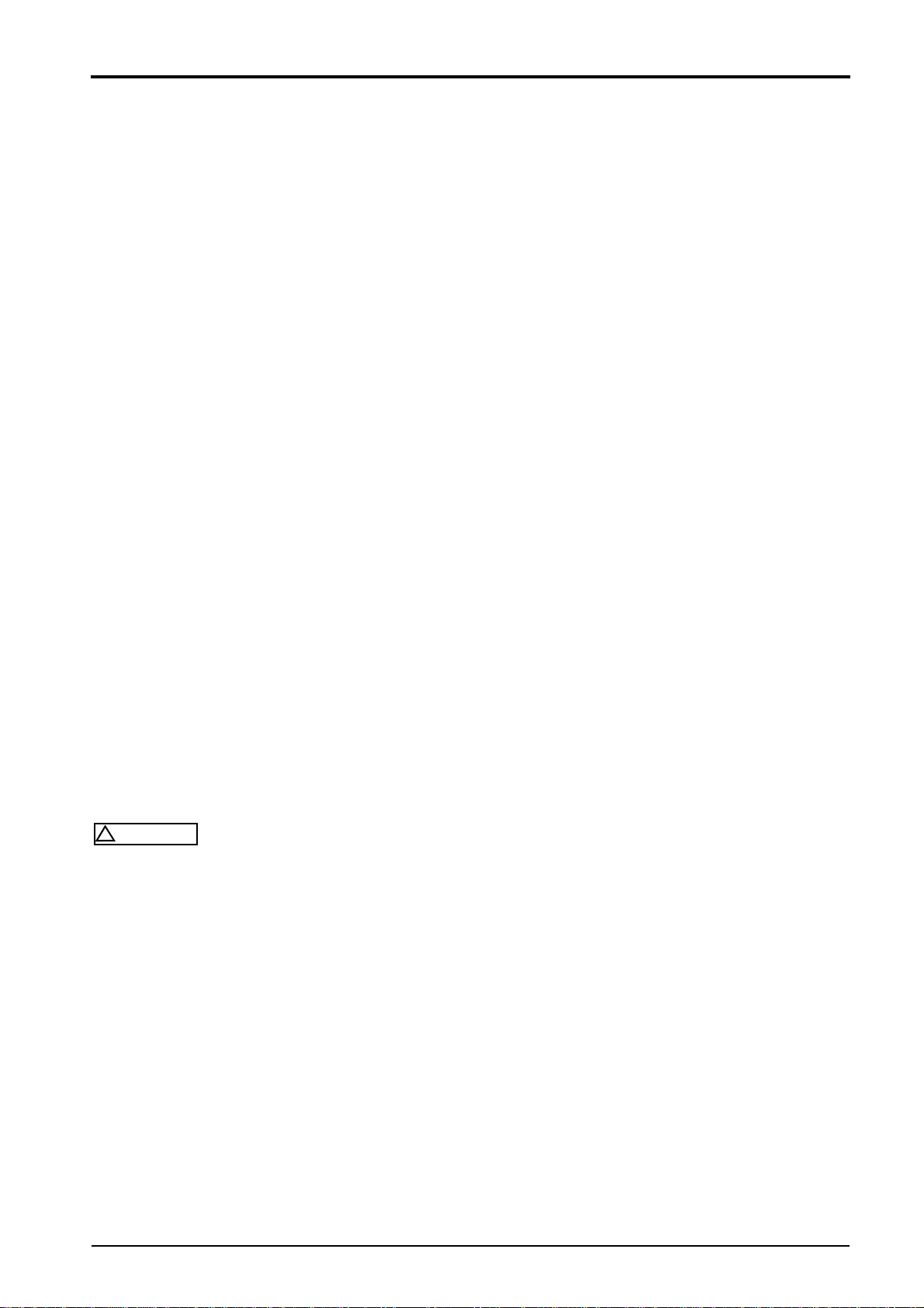
Assembly of radial seals
Fig. 2
lLubricate sealing lips1 (Fig. 2) with clean grease; in
case of double seals fill the space between the seal-
ing lips with a generous amount of grease.
lSlide the seal over the shaft, with the lip facing to-
wards the fluid to be sealed.
i
Note
If possible, use an assembly sleeve 1 (Fig. 2), to pro-
tect the lip from being damaged by sharp edges,
threads or splines. If no assembly sleeve is availa-
ble, you should use a plastic tube or adhesive tape to
prevent the sealing lip from being damaged.
Fig. 3
lLubricate the outer rim 1 (Fig. 3) of the seal and
press it flat on the housing seat.
i
Note
If possible, use a "bell" 1 (Fig. 3), to make sure that
the seal will not skew. In some cases it may be ad-
visable to assemble the seal into the housing first, be-
fore sliding it over the shaft. Under no circumstances
should the full weight of the shaft rest on the seal.
If you have no proper service tools at hand, use a suit-
able drift punch with a diameter which is about 0.4mm
smaller than the outer diameter of the seal. Use VERY
LIGHT blows with the hammer if no press is available.
lPress or knock the seal into the housing, until it is
flush with the housing surface.
1.3 General repair instructions
BOMAG20 008 911 45
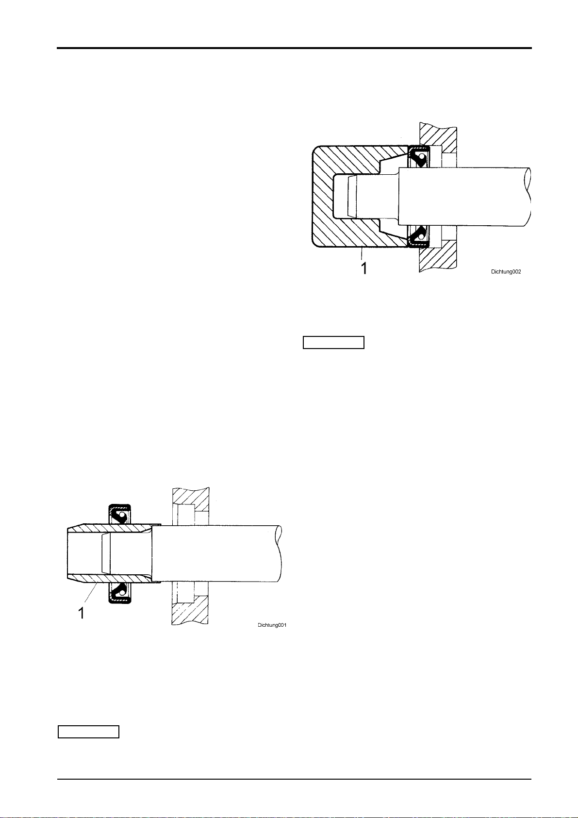
Feather keys and keyways
!
Caution
Feather keys must only be reused if they show no
differences to new feather keys, any notches must
be considered as initial signs of wear.
Fig. 4
lClean and thoroughly examine the feather key.
lDebur and thoroughly clean the edges of the key-
way with a fine file before reassembling.
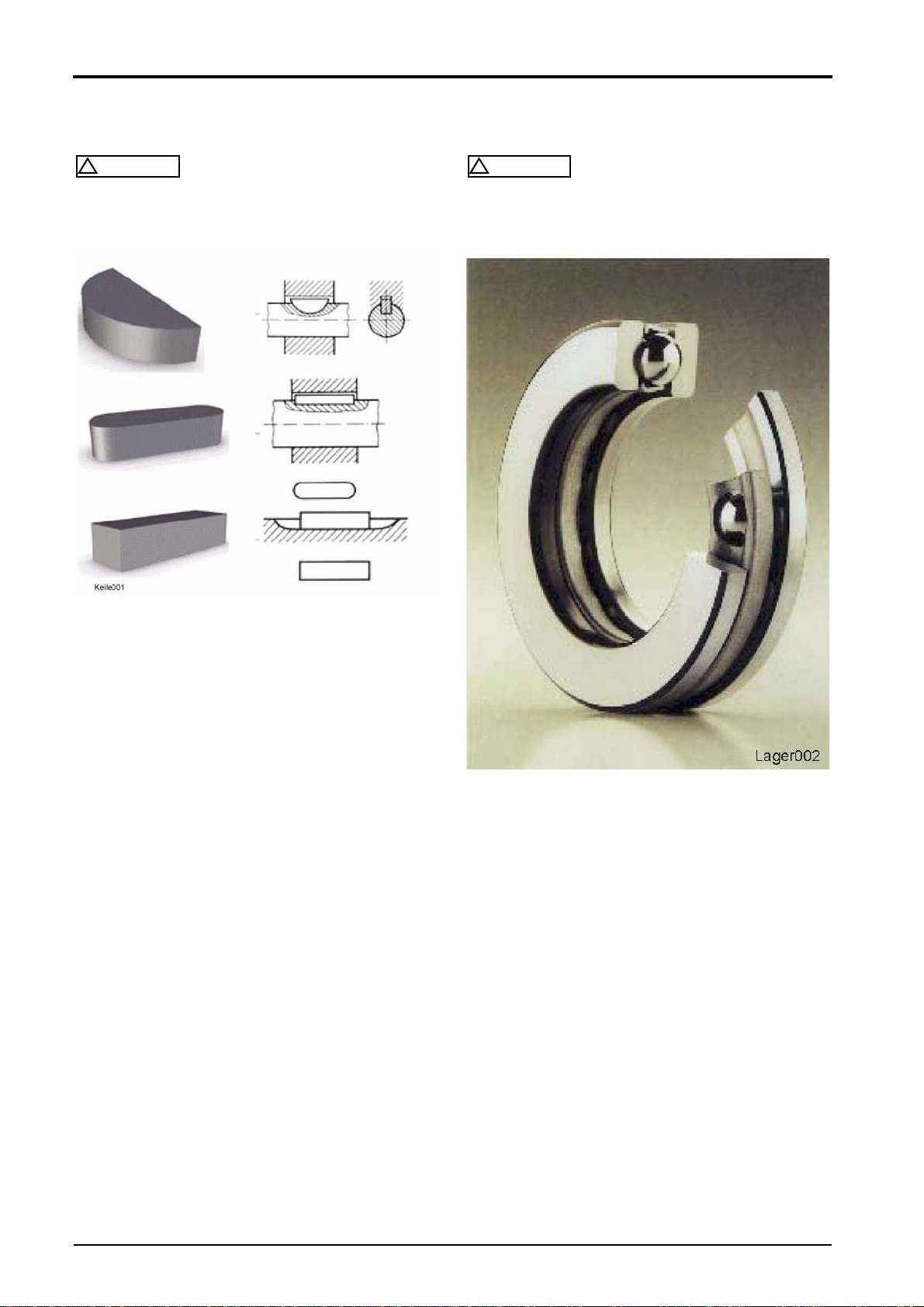
Ball and roller bearings
!
Caution
Ball and roller bearings must only be reinstalled
after it has been assured that they are in perfect
condition.
Fig. 5
lRemove any lubricant residues from the bearing to
be examined by washing it with gasoline or any oth-
er appropriate degreasing agent. Cleanliness is of
utmost importance for all related work.
lCheck balls or rollers, running surfaces, outer faces
of outer races and inner faces of inner races for vis-
ible damage. If necessary replace the bearing with
a new one, since these symptoms are first signs of
wear.
lHold the bearing with you thumb and the index fin-
ger by the inner race, rotate the outer race and
make sure that it runs without friction. Hold the
bearing by the outer race and repeat this test with
the inner race.
lMove the outer race gently to and fro while holding
it by the inner race; check for resistance while rotat-
ing and replace the bearing if it does not work cor-
rectly.
lLubricate the bearing with an appropriate lubricant
before reinstalling.
This manual suits for next models
3
Table of contents
Other Bomag Construction Equipment manuals

Bomag
Bomag BW 154 AP-4 User manual

Bomag
Bomag BW 156 D-3 User manual

Bomag
Bomag BW 213 D-4 Instructions for use

Bomag
Bomag BVP 10/36 User manual

Bomag
Bomag BW 900-2 User manual

Bomag
Bomag BT 60/4 User manual

Bomag
Bomag BW 100 AD-5 Installation and operation manual

Bomag
Bomag BW 177 D-4 User manual

Bomag
Bomag BW 211 D-40 User manual

Bomag
Bomag BW 100 AD-4 User manual


