Bomba Elias BF Series Guide

P á g i n a 1 | 28
Manual de instrucciones/Manual/Manuel d’instructions BF

SERIE “BF”
Manual de instrucciones/Manual/Manuel d’instructions “BF”
P á g i n a 2 | 28
Tabla de contenido/Table of contents/Table des matières
ELECTROBOMBAS DE ENGRANAJES PRESIÓN REGULABLE SERIE “BF”.......................................................4
Introducción .................................................................................................................................................4
Presentación.................................................................................................................................................4
Advertencia sobre seguridad y modos de utilización ...........................................................................5
Transporte y almacenamiento ..................................................................................................................5
Instalación y montaje..................................................................................................................................6
Montaje de tuberías....................................................................................................................................6
Conexión eléctrica......................................................................................................................................6
Controles previos a la puesta en marcha inicial ....................................................................................7
Puesta en marcha .......................................................................................................................................7
Regulación....................................................................................................................................................7
Mantenimiento y conservación.................................................................................................................7
Esquemas de conexionado .......................................................................................................................8
Advertencias sobre seguridad y modos de utilización..........................................................................8
Posibles averías ..........................................................................................................................................10
Despiece conjunto....................................................................................................................................11
ADJUSTABLE PRESSURE GEAR PUMPS “BF” SERIES ......................................................................................12
Introduction ................................................................................................................................................12
Presentation................................................................................................................................................12
Warning on safety and use ......................................................................................................................13
Transport and storage...............................................................................................................................13
Description of the pump...........................................................................................................................13
Installation and assembly .........................................................................................................................14
Assembly of pipes ......................................................................................................................................14
Electrical connection ................................................................................................................................14
Controls prior to initial start-up .................................................................................................................14
Start-up........................................................................................................................................................15
Regulation...................................................................................................................................................15
Maintenance and conservation.............................................................................................................15
Connection symbols..................................................................................................................................16
Advice on safety and use........................................................................................................................16
Possible faults..............................................................................................................................................18
Exploded view............................................................................................................................................19
POMPES À ENGRENAGES RÉGLABLES SÉRIE “BF”.......................................................................................20
Introduction ................................................................................................................................................20
Présentation................................................................................................................................................20

SERIE “BF”
Manual de instrucciones/Manual/Manuel d’instructions “BF”
P á g i n a 3 | 28
Avertissements de sécurité et sur les modes d’utilisations ...................................................................20
Transport et stockage ...............................................................................................................................21
Description de la pompe..........................................................................................................................21
Installation et montage.............................................................................................................................21
Montage des tuyaux.................................................................................................................................22
Connexion électrique ...............................................................................................................................22
Mise en route..............................................................................................................................................22
Réglages .....................................................................................................................................................23
Entretien et conservation..........................................................................................................................23
Schémas de connexions...........................................................................................................................23
Avertissements de sécurité et sur les modes d’utilisations ...................................................................23
Problèmes possibles...................................................................................................................................25
Vue éclatée................................................................................................................................................26
Departamento/Département/Department/Abteilung...........................................................................27

SERIE “BF”
Manual de instrucciones/Manual/Manuel d’instructions “BF”
P á g i n a 4 | 28
ELECTROBOMBAS DE ENGRANAJES PRESIÓN REGULABLE SERIE “BF”
Introducción
BOMBA ELIAS, desarrolló hace años este nuevo concepto de bomba que ha ido
evolucionando conforme los combustibles también lo han hecho.
Presentación
El presente manual viene estructurado conforme a la siguiente disposición:
-Generalidades.
-Transporte y almacenamiento.
-Descripción de la bomba.
-Instalación/Montaje.
-Puesta en servicio.
-Mantenimiento y conservación.
-Fallos: causas y resolución.
-Documentación correspondiente.
SEDE CENTRAL
Crta Molins de Rei a Rubí, km
8’7
08191 Rubí (Barcelona)
Tel: 93.699.60.04
Fax: 93.697.16.09
Email: info@elias.es
www.elias.es

SERIE “BF”
Manual de instrucciones/Manual/Manuel d’instructions “BF”
P á g i n a 5 | 28
Advertencia sobre seguridad y modos de utilización
Esta simbología junto con las palabras “peligro” y “atención” indican
la posibilidad de peligro como consecuencia de no respetar las prescripciones
correspondientes.
PELIGRO La no advertencia de esta prescripción comporta un riesgo de
electrocución.
PELIGRO La no advertencia de esta prescripción comporta un riesgo de daño
a las personas o cosas.
ATENCIÓN La no advertencia de esta prescripción comporta un riesgo de
daños a las personas o cosas.
Antes de usar el equipo lea atentamente el presente manual, es necesario para el
conocimiento y buen uso de la bomba, asegurando la obtención del máximo rendimiento,
considerando la seguridad del operario.
La parte eléctrica de la bomba debe manipularse con la bomba parada y SIN TENSIÓN,
deberá dejarse la caja de bornes cerrada.
El equipo deberá constar de dispositivos de desconexión eléctrica e hidráulica, así permitirá
efectuar labores de mantenimiento de una forma segura.
Transporte y almacenamiento
La bomba no requiere condiciones especiales de transporte, y va protegida
convenientemente con un embalaje adecuado.
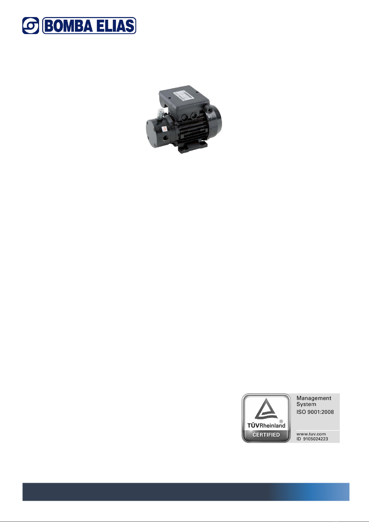
Descripción de la bomba
Bombas de engranajes en acero, cuerpo en hierro fundido GG-25, equipadas con válvula de
control de presión, regulable de amplia dimensión para permitir un funcionamiento continuo
con gas-oil, gasóleo limpio.
Motores eléctricos construidos según normativa Europea vigente, con componentes de 1ª
Calidad, sometidos a rigurosas pruebas.
!
SERIE “BF”
Manual de instrucciones/Manual/Manuel d’instructions “BF”
P á g i n a 6 | 28
Instalación y montaje
El grupo puede instalarse en posición vertical u horizontal sobre una superficie sólida
y plana, mediante tornillos y arandelas antivibración, aprovechando los agujeros
existentes en el motor, con objeto de evitar ruidos y vibraciones.
Se colocará lo más cerca posible del nivel de líquido a fin de obtener el mínimo
recorrido de aspiración, y la reducción de las pérdidas de carga.
Se procurará que esté a salvo de posibles inundaciones y reciba una ventilación de
carácter seco.
Instalar un manómetro en la Impulsión para poder fijar la presión de trabajo de la
bomba.
Montaje de tuberías
La tubería de aspiración y la de impulsión debe poseer un diámetro igual o superior al de la
boca de entrada de la bomba.
Deben ser herméticas, las entradas de aire provocan pérdida de aspiración en la bomba.
Reducir al mínimo codos, estrangulamientos que aumentan las pérdidas de carga.
Instalar siempre un filtro de malla adecuado al fluido a trasegar en la tubería de aspiración.
La válvula de pie si bien no es imprescindible, es conveniente instalarla.
Instalar un manómetro en la impulsión y un vacuo metro en aspiración.
Ni la tubería de aspiración ni la de impulsión deben descansar su peso sobre la bomba.
Conexión eléctrica
El cable de alimentación debe corresponder a la norma CEE o bien tipo HO7RN-F
según VDE O25O. La instalación eléctrica debe disponer de un sistema de
protección por interruptor diferencial.
Los motores monofásicos llevan protección térmica incorporada.
Motores trifásicos, el usuario debe prever una protección de acuerdo con las normas
de instalación vigentes.
Los esquemas de conexionado (ver dibujo), facilitan una correcta conexión
eléctrica.

SERIE “BF”
Manual de instrucciones/Manual/Manuel d’instructions “BF”
P á g i n a 7 | 28
Controles previos a la puesta en marcha inicial
Compruebe que la tensión y frecuencia de la red corresponden a las indicadas en
la placa de características. Asegúrese de que el eje del motor gira libremente.
Compruebe que el sentido de giro del motor coincida con el indicado en la tapa
del ventilador.
En los motores trifásicos, si el sentido de giro es erróneo, invierta dos fases en el
cuadro de protección.
Puesta en marcha
Abra todas las válvulas de compuerta que existan en los circuitos de aspiración e impulsión.
Compruebe la corriente absorbida y ajuste debidamente el relé térmico sólo en el caso de
la versión trifásica.
Si la bomba no funcionara o no extrajera el caudal de líquido indicado, procure descubrir la
anomalía a través de la relación de averías más habituales y sus posibles resoluciones que
facilitamos en páginas posteriores.
Regular la presión de servicio con un destornillador actuando sobre la válvula que hay en el
cuerpo de la bomba.
Regulación
Una vez el circuito está lleno de líquido y la bomba en marcha, regular la presión del circuito
mediante el tornillo regulador al punto deseado. Parar la bomba y ponerla en marcha varias
veces comprobando que el circuito se estabiliza a la presión deseada, es conveniente utilizar
manómetro de glicerina para ver mejor la presión de trabajo.
Al ponerse en marcha el quemador o quemadores la presión descenderá pero volverá a
estabilizarse en breves instantes.
Mantenimiento y conservación
Nuestras bombas no necesitan ningún tipo de mantenimiento.
Únicamente se recomienda, periódicamente, limpiar el filtro situado en la aspiración.
Para almacenar la bomba, limpiarla previamente, poner aceite en los engranajes y guardar
en lugar seco.

SERIE “BF”
Manual de instrucciones/Manual/Manuel d’instructions “BF”
P á g i n a 8 | 28
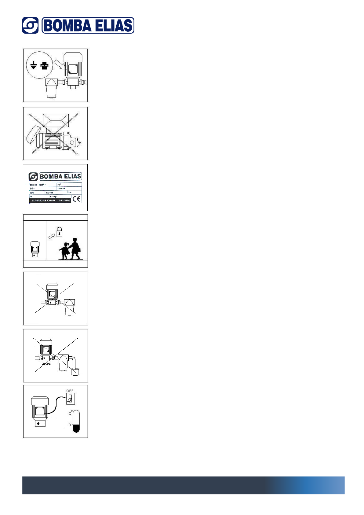
Esquemas de conexionado
Advertencias sobre seguridad y modos de utilización
1.- La tensión indicada en la placa debe ser la misma que la de la
red.
2.- Características de funcionamiento figuran en la placa,
comprobar que son las deseadas.
3.- Para conectar la electrobomba a la red, utilice un interruptor que
interrumpa todos los hilos de alimentación.
Como protección a las descargas eléctricas letales, instale un
interruptor diferencial.

SERIE “BF”
Manual de instrucciones/Manual/Manuel d’instructions “BF”
P á g i n a 9 | 28
Conexione la toma de tierra de la electrobomba.
4.- Controle que el motor tiene una buena ventilación.
5.- Usar la bomba para las prestaciones indicadas en la placa.
6.- No instalar la electrobomba al alcance de los niños.
7.- No exponga la electrobomba a la intemperie y vigile las posibles
fugas accidentales.
Atención a líquidos y ambientes peligrosos.
8.- Desconectar eléctricamente la electrobomba antes de
cualquier manipulación de mantenimiento.
Precaución a la formación de hielo.

SERIE “BF”
Manual de instrucciones/Manual/Manuel d’instructions “BF”
P á g i n a 10 | 28
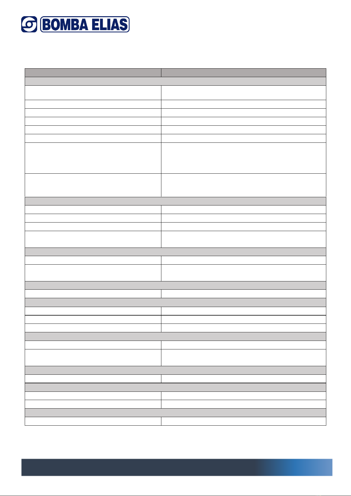
Posibles averías
POSIBLE CAUSA
SOLUCIÓN
CAUDAL INSUFICIENTE
- Tubería de aspiración de diámetro
insuficiente.
Cambiar a diámetro igual ó mayor que el de la
bomba
- Válvula de aspiración parcialmente abierta.
Limpiar ó cambiar
- Entradas de aire en la aspiración.
Revisar toda la aspiración incluidas uniones
- Líquidos muy viscosos.
Calentar liquido
- Sentido de giro incorrecto.
Cambiar sentido de giro
- Filtro obstruido.
Limpiar
- Mala instalación de la tubería de aspiración, con
contrapendientes que provocan la formación de
bolsas de aire.
Revisar la instalación, eliminar contrapendientes
- Presión de trabajo superior a la máxima, lo que
provoca la apertura de la válvula de seguridad de
la bomba.
Regular presión, bajar esta
PRESIÓN INSUFICIENTE O INESTABLE
- Válvula de aspiración parcialmente
cerrada.
Revisar válvula-cambiar
- Entrada de aire en aspiración.
Revisar toda la instalación incluido uniones
- Sentido de giro incorrecto.
Cambiar sentido de giro
- Contrapendientes en la aspiración con
formación de bolsas de aire.
Revisar la instalación, eliminar contrapendientes
FUGAS POR EL CIERRE MECÁNICO Ó RETENES
- Impurezas en el líquido bombeado.
Colocar filtro, cambiar cierre mecánico o retén
- Caras de roce dañadas por trabajar en seco,
labio retenes en mal estado.
Cambiar cierre o retén
GRIPADO DE LAS PARTES GIRATORIAS
- Aspiración de cuerpos extraños.
Limpiar el interior y verificar que no esté dañado
FUNCIONAMIENTO ANORMAL DEL MOTOR
- Alimentación eléctrica incorrecta.
Verificar tensión
- Mala conexión del motor.
Verificar conexiones
- Gripado parcial en alguna parte de la
bomba.
Limpiar el interior y verificar que no esté dañado
LA BOMBA ABSORBE UNA POTENCIA EXCESIVA
- Densidad o viscosidad del líquido muy alta.
Calentar liquido
-Trabaja fuera de curva a la máxima
presión.
Regular presión
FUGA ORIFICIO CUERPO Y MOTOR
- Cierre mecánico ó retén averiado.
Cambiar cierre ó reten
TEMPERATURA DE OPERACIÓN EXCESIVA
- Mala ventilación del equipo.
Procurar ventilación ó cambiar de ubicación
- Temperatura de bombeo muy alta.
Comprobar temperatura del liquido
FALLOS SISTEMÁTICOS DEL CIERRE MECÁNICO Ó RETENES
- Partículas abrasivas en el fluido.
Evitar partículas-colocar filtro
SERIE “BF”
Manual de instrucciones/Manual/Manuel d’instructions “BF”
P á g i n a 11 | 28
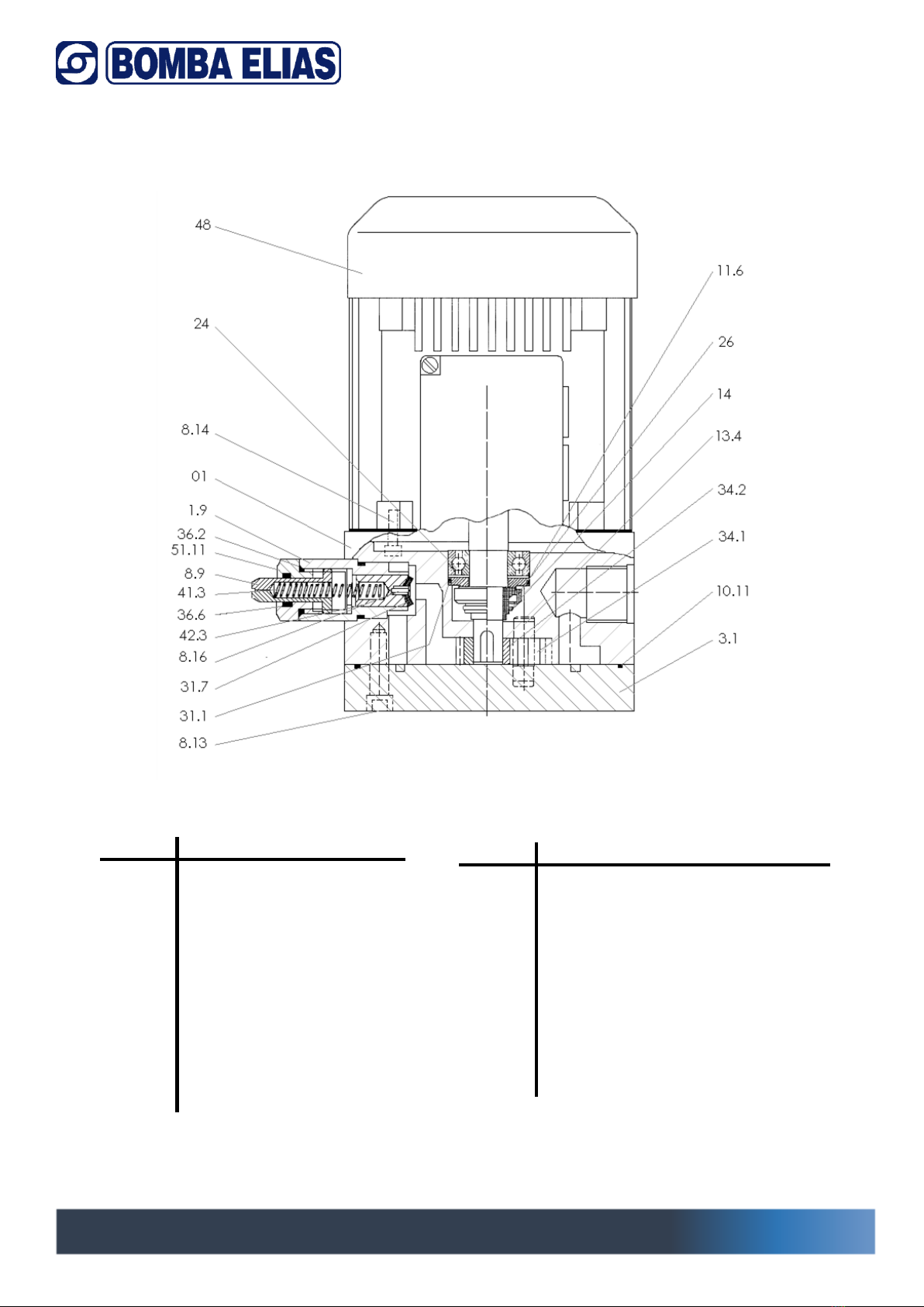
Despiece conjunto
Núm.
Denominación
01
Cuerpo
13.4
Eje engranaje conductor
14
Seager
3.1
Tapa bomba
24
Contrasello
26
Cierre mecánico
34.2
Engranaje conductor
34.1
Engranaje conducido
10.11
Junta cuerpo tapa
11.6
Junta tórica contrasello
31.1
Arandela tope
51.11
Tapón válvula
Núm.
Denominación
41.3
Muelle válvula
42.1
Pistón válvula
31.7
Arandela pistón
11.21
Junta tórica válvula
8.13
Tornillo sujeción tapa
8.14
Tornillo sujeción motor
8.16
Tornillo sujeción arandela válvula
48
Motor
1.9
Cuerpo válvula
8.9
Tornillo regulador
11.12
Junta tórica regulador
“BF” SERIES
Manual de instrucciones/Manual/Manuel d’instructions “BF”
P á g i n a 12 | 28
ADJUSTABLE PRESSURE GEAR PUMPS “BF” SERIES
Introduction
BOMBA ELIAS has developed, years ago, this new concept of pumps that has been evolved as
fuels also have.
Presentation
This manual is composed as follows:
-Generalities
-Transport and storage
-Description of the pump
-Installation/Assembly
-Start up
-Maintenance and conservation
-Faults: causes and solutions
-Relative literature
SEDE CENTRAL
Crta Molins de Rei a
Rubí, km 8’7 08191
Rubí (Barcelona )
Tel: 93.699.60.04
Fax: 93.697 .16.09
www.elias.es

“BF” SERIES
Manual de instrucciones/Manual/Manuel d’instructions “BF”
P á g i n a 13 | 28
Warning on safety and use
These symbols together with the words “danger” and “attention”
indicate risk possibilities due to not respecting the corresponding indications.
DANGER To disregard this warning could mean a risk ofelectrocution.
DANGER To disregard this warning could mean harm to personsor objects.
ATTENTION To disregard this warning could mean harm to the installation or to the pump.
Before using the equipment, carefully read through this manual. It is necessary for your
understanding and correct use of the pump and assures maximum performance whilst
considering the safety of the worker.
The electric part of the pump should be handled with the pump stopped and WITHOUT
TENSION, the terminals box should be closed.
The equipment should have electric and hydraulic disconnection devices, as well as allowing
any maintenance work to be made safely.
Transport and storage
The pump does not require any special transport conditions and is conveniently protected with
adequate packing.
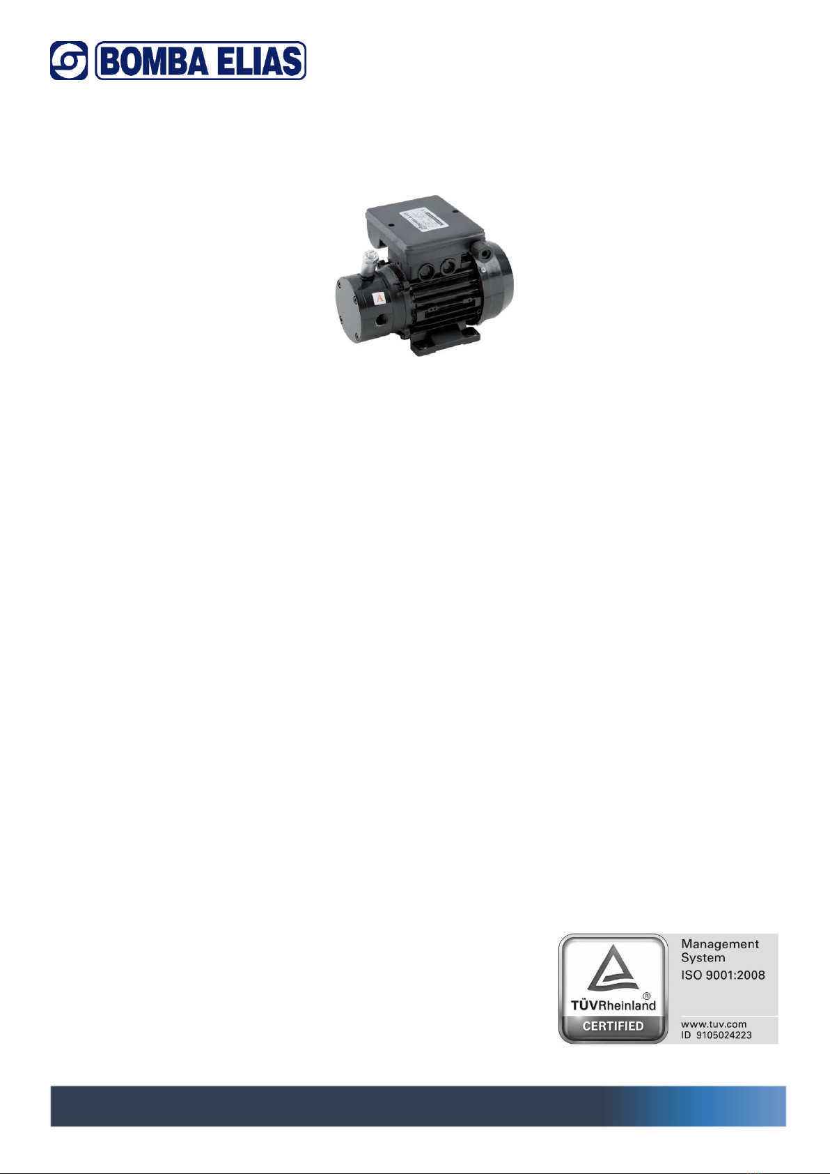
Description of the pump
Gear pumps in steel, cast iron casing and cover, equipped with a safety valve for overload
pressure, for intermittent service, for working with clean oils and gasoils.
They are equipped with electric motors, as per the European standard in force, with first class
components, and are subjected to rigorous testing.
“BF” SERIES
Manual de instrucciones/Manual/Manuel d’instructions “BF”
P á g i n a 14 | 28
Installation and assembly
The group can be installed vertically or horizontally on a solid flat surface by screws and
antivibration washers, using the existing holes in the engine, in order to avoid noise
and vibration.
Be placed as close to the liquid level to obtain the minimum suction path,
and reducing losses. It should be safe from any possible flooding and well ventilated.
(Dry ventilation)
Install a manometer on the Impulsion to set the pressure of the pump.
Assembly of pipes
The suction and discharge pipes should have a diameter the same or superior to the inlet of the
pump. They must be hermetic, air intake causes suction loss in the pump.
Reduce to a minimum any elbow joints, strangling, all of which increase the load losses. Always
install a filtering mesh adequate for the fluid to be pumped on the suction pipe. Although it is
not absolutely necessary, it is convenient to install a foot valve.
Install a manometer on the impulsion and a meter in aspiration.
Neither the suction nor the discharge pipes should rest their weight on the pump.
Electrical connection
The electric cable should correspond to EEC standards or to type HO7RN-F as per VDE
0250.
The electrical installation should be protected by means of a differential switch.
Single-phase motors are incorporated with thermal protection.
For three-phase motors the end-user should foresee protection as per the legislation in
force.
The connection symbols (see drawing) make the electric connection easy.
Controls prior to initial start-up
Check that the tension and frequency of the mains correspond to those indicated
on the characteristics plaque. Make sure that the motor shaft turns freely.
Check that the sense of rotation of the motor coincides with that indicated on the fan
cover.
On three-phase motors, if the sense of rotation is incorrect, invert two phases on the
protection panel.

“BF” SERIES
Manual de instrucciones/Manual/Manuel d’instructions “BF”
P á g i n a 15 | 28
Start-up
Open all gate valves exist in the inlet and outlet circuits.
Check the current absorbed, and adjust properly the thermal relay only in the case of three-
phase version.
If the pump does not work or not to extract the liquid flow indicated, try to discover the
anomaly through the list of common faults and their possible resolutions provided on subsequent
pages.
Regular operating pressure with a screwdriver, acting on the valve on the pump body.
Regulation
Once the circuit is filled with fluid and the pump running, pressure regulating circuit by the
adjustment screw to the desired point. Stop the pump and put it running several times checking
that the circuit stabilizes at the desired pressure; it is convenient to use a manometer of glycerin
to better see the pressure.
At start up the burner or burners the pressure will fall but the pressure will stabilize in a few
moments.
Maintenance and conservation
Our pumps do not need any type of maintenance. It is only recommended, to periodically clean
the filter that is situated on the suction.
To store the pump, first clean it, oil the gears and store in a dry place.

“BF” SERIES
Manual de instrucciones/Manual/Manuel d’instructions “BF”
P á g i n a 16 | 28
Connection symbols
Single phase connection Three phase connection
Advice on safety and use
1. - The tension indicated on the plaque must be the same as that of
the mains.
2. - The working data figure on the plaque, check that they are those
desired.
3. - To connect the pump to the mains, use a switch that cuts off the
power. Install a differential switch as protection against lethal electric
discharges.
“BF” SERIES
Manual de instrucciones/Manual/Manuel d’instructions “BF”
P á g i n a 17 | 28
Connect the earth of the electric pump.
4.- Control that the motor is well ventilated
5.- Use the pump for the performance indicated on the plaque
6.- Do not install the electric pump within the reach of children.
7.- Do not expose the pump outdoors and check any possible
accidental leaks.
Be careful of dangerous liquids and atmospheres
8.- Disconnect the pump from the mains before handling for repairs.
Take care against the formation of ice.
“BF” SERIES
Manual de instrucciones/Manual/Manuel d’instructions “BF”
P á g i n a 18 | 28
Possible faults
FAULT
SOLUTION
INSUFFICIENT FLOW
- Insufficient suction pipe diameter.
Change a diameter equal to or greater than the
pump
- Suction valve partially open.
Clean or change
- Air intake on the suction.
Check all suction connections
- Very viscous liquids.
Heat liquid
- Wrong turning direction.
Change rotation
- Blocked filter.
Clean
- Incorrect installation of the suction pipe
with
countergradients that cause the formation
of air pockets.
Check the installation, delete counterslope
- Working pressure higher than the
maximum, which causes the safety valve to
open.
Regular pressure
INSUFFICIENT OR UNSTABLE PRESSURE
- Suction valve partially closed.
Check valve -change
- Air intake on the suction.
Review all the unions included installation
- Wrong turning direction.
Change rotation
- Countergradients on the suction that
cause the formation of air pockets.
Check the installation, delete counterslope
LEAKS THROUGH THE MECHANICAL SEAL OR LIPSEALS
- Impurities in the pumped liquid.
Insert filter, change the mechanical seal or seal
- Damaged friction faces due to working
dry, damaged lipseals.
Switch closure or seal
BLOCKING OF THE TURNING PARTS
- Suction of foreign bodies.
Clean the inside and check for damage
ABNORMAL WORKING OF THE MOTOR
- Incorrect electric supply.
Check voltage
- Incorrect motor connection.
Check connections
- Partial blocking in some part of the pump.
Clean the inside and check for damage
THE PUMP ABSORBS EXCESSIVE POWER
- Very high density or viscosity of the liquid.
Heat liquid
- The pump works outside the maximum
pressure curve.
Adjust pressure
LEAK THROUGH PUMP & MOTOR OPENING
- Damaged mechanical seal or lipseal.
Switch closure or retention
EXCESSIVE WORKING TEMPERATURE
- Incorrect ventilation of the equipment.
Ensure ventilation or relocate
- Very high pumping temperature.
Check temperature of liquid
SYSTEMATIC FAULTS OF THE MECHANICAL SEAL OR LIPSEALS
- Abrasive particles in the fluid.
Avoid placing particulate filter

“BF” SERIES
Manual de instrucciones/Manual/Manuel d’instructions “BF”
P á g i n a 19 | 28
Exploded view
Num.
Designation
01
Casing
13.4
Drive shaft
14
Seager
3.1
Pump cover
24
Stationary mechanical seal
26
Mechanical seal
34.2
Drive shaft gear
34.1
Layshaft gear
10.11
Casing-cover joint
11.6
Mechanical seal o-ring
31.1
Lock washer
51.11
Valve plug
Num.
Designation
41.3
Valve spring
42.1
Valve piston
31.7
Piston washer
11.21
Valve o-ring
8.13
Cover fastening screw
8.14
Motor fastening screw
8.16
Valve washer fastening screw
48
Motor
1.9
Valve casing
8.9
Regulating screw
11.12
Regulating screw joint
SÉRIE “BF”
Manual de instrucciones/Manual/Manuel d’instructions “BF”
P á g i n a 20 | 28
POMPES À ENGRENAGES RÉGLABLES SÉRIE “BF”
Introduction
BOMBA ELIAS, a développé, depuis des années, ce nouveau concept de pompes qui a suivi
l’évolution des combustibles que nous utilisons.
Présentation
Sommaire:
- Généralités.
- Transport et stockage.
- Description de la pompe.
- Installation/Montage.
- Première utilisation.
- Entretien et conservation.
- Problèmes: causes et solutions.
- Documentation correspondante.
SEDE CENTRAL
Crta Molins de Rei a Rubí, km 8’7
08191 Rubí (Barcelona)
Tel: 93.699.60.04
Fax: 93.697.16.09
Email: info@elias.es
www.elias.es
Table of contents
Languages:
Other Bomba Elias Water Pump manuals


Popular Water Pump manuals by other brands

Grundfos
Grundfos CR instructions

Homa
Homa C240WF Original instruction manual

Bijur Delimon
Bijur Delimon DP5 quick start guide

Pentair
Pentair MYERS CT Series Installation and operation manual

Wilo
Wilo Economy-MHI 2 Series Installation and operating instructions

Proline
Proline WFP1600 Care and operating instructions


